Dhae H. Al-Badri* | Ali A.F. Al-Hamadani | Ahmed H. Al-Hassani
© 2022 IIETA. This article is published by IIETA and is licensed under the CC BY 4.0 license (http://creativecommons.org/licenses/by/4.0/).
OPEN ACCESS
This research examines the heat sources using a low-temperature organic Rankine cycle thermodynamic analysis. The effect of increasing the temperature and pressure at the expander input is explored. The performance of an ORC system using R134a was investigated thermodynamically. The expander's input temperature ranged from 55 to 85 degrees Celsius. Pressures in the evaporator range from 0.4 to 0.6 MPa. The software used was Engineering Equation Solver. The temperature and pressure of evaporation have an impact on cycle characteristics including net power production, irreversibility, rotational speed, and thermal and exergy efficiency. At constant evaporator pressure of 0.6 MPa and rising temperature, the thermal efficiency drops to 3.907%, whereas at constant evaporator temperature and expander pressure of 0.4-0.6 MPa, the thermal efficiency rises to 3.907%. When the exergy efficiency is 0.6MPa at constant evaporator pressure, raising the temperature leads to an increase in exergy efficiency of 18.81% -18.89%. At 85℃ and a pressure of 0.4-0.6 MPa, the effect of increasing exergy efficiency was between 2.185% and -18.89% at constant evaporator temperature. The findings of the research reveal that the ORC power plant is a good choice for energy generation. R134a is suitable for the ORC system.
exergy efficiency, engineering equation solver EES, ORC, R134a, superheated, thermal efficiency
An alternative to the traditional Rankine cycle, known as the Organic Rankine cycle (ORC), makes use of organic fluid instead of water and is frequently used in low-grade heat recovery applications. It is possible to increase the engine’s thermal efficiency and performance by converting the heat into mechanical or electrical power. Low-quality heat sources with thermodynamic properties and organic fluids below 100℃ require low-quality heat sources [1]. Selecting an organic fluid with a lower critical temperature and a bigger molecular mass than water helps to mitigate some of water's issues with ORC's low temperature thermodynamic cycle (ORC). To spin an expander, an organic working fluid is utilized [2].
An experimental model of the organic Rankine cycle (ORC) for working with R123 is presented by Quoilin et al. [3]. The operating conditions were a mass flow rate of 0.071-0.90 kg. s-1, and the speed of rotation of the expander of 1771-2660 rpm. The prototype’s performance was achieved at 39 points. They found that the efficiency of the extender ranged from 42 to 68%, which corresponds to a maximum cycle efficiency of 7.4%. The expander compression ratio ranged from 2.7 to 5.4 and clearly impacted system performance. Kalinci et al. [4] studied binary thermal power plants with an organic Rankine cycle for isopentane working fluid. External exergy destruction rates across the plant have been determined and illustrated for comparison purposes. Some important variables were studied: the inlet temperature, the upper cycle pressure, and the turbine inlet temperature. Energy and Exergy efficiencies were calculated as 5.34% and 30.84%, respectively. The net power of 2184 kW is dependent on the rates of heat input into the system. They can be used for low-temperature applications to increase energy/exergy efficiency. Martin et al. [5] Utilized R134a as a working fluid and a temperature range of 75℃-95℃ as a heat source, experimental research was done on ORC systems using solar energy as a heat source. The heat source used was 4080.8 kJ and the highest efficiency was 4.30%, with the evaporator’s water temperature starting at 51℃. as a source of heat in the experiment generated 185.9 watts of system power as a result of the experiment. For a 95°C heat source, the turbine's inlet pressure is 1.38 MPa and the turbine’s inlet temperature is 67.9℃. Colak et al. [6] geothermal source was used to examine the impact of working fluid pressure fluctuations on ORC performance for R141b and R123. Shell and tube-type heat exchangers were used in the evaporator and condenser. R141b outperformed R123 in terms of performance. By altering the maximum cycle pressure, which maintains a 200 kPa minimum pressure. The working fluid R141b has net power, thermal, and energy efficiencies of 2331 kW, 17.10%, and 54.19. Also, for R123, these values were determined as 1798 kW, 16.88%, and 56.29%, correspondingly. The ORC system was conceived and constructed as a shell-and-tube with an evaporator and condenser, a helical tube condenser utilizing R-134a [7]. The evaporator tube length was 10.61 m, the condenser tube length was 10.56 m, with an efficiency of 3.8%, and the turbine power was 1110 watts. Wang et al. [8] an off design ORC system for 10 kW waste heat recovery was evaluated for performance. This material is commonly used in three-phase plate-type heat exchangers. The impact of R245fa working liquid being heated to a superheated temperature was examined. Superheated temperatures reduce thermal and exergy efficiency; therefore, the working fluid does not need to be excessively heated. Enthalpy increases at the expander inlet lead to changes in net power output, which first claimed and then declined as the flow rate fell. Wang et al. [9] investigated a low temperature solar thermal system with pure HFC-R245fa and a zeotropic mixture. The output power was 7.2 W, and the efficiency of the ORC was 5.59%. highlighted that utilizing an R245fa/R152 combination rather than pure R245fa significantly improved system efficiency. The thermodynamics and power generation potential of the Vélez et al. [10] low-temperature (150℃) heat source for the Rankine power cycle with R134a as the working fluid have been investigated. The input pressure and temperature of the working fluid were used to analyze behavior under conditions of both saturation and overheating circumstances. The results reveal the turbine’s efficiency improves with increasing pressure ratio and also with increasing temperature input to the turbine. A maximum efficiency of 11% is achieved as a result. Vignesh et al. [11] investigated the ORC experimentally using a radial-turbine expander and the working fluid hexane HFE-7000. Temperatures ranged from 120 to 190 degrees Celsius, with mass flow rates ranging from 0.1 to 0.50 kg.s-1. They found that raising the flow rate would lead to an increase in the inlet pressure and temperature. The thermal efficiency was 5.57%, the power output was 1.75 kW, and the turbine speed was 39.802-52.189 rpm. A review of Polish experimental research and modelling on the application of a multi-feather expander in ORC systems for 15 working fluids is discussed by researcher Kolasiński [12]. This study examines an extended design’s applied working fluids, acquired power output, and efficiency. The expanders' output power and rotational speed ranged from 65-8 kW to 1200-4100 rpm. The working fluid pressure ranges 1.5-6.39 bar as the expander’s inlet. Organic Rankine cycle system is designed to produce 534.4 watts, but when the experiment is carried out, the system generates 305 watts with an efficiency of 4.30% [13]. Fatigati et al. [14] worked using R245fa working fluid in a 1.5 kW expander machine that had been experimentally expanded with an ORC. During the course of the experiments, a number of different aspects were scrutinized. The expander’s intake pressure ranges from 6.2 bar to 11.2 bar, with a 3250 rpm rotational speed. The cycle's highest efficiency was found to be 12%. Hartulistiyoso et al. [15] four working fluids, including R134a, were investigated to see if the evaporator and condenser temperatures affected efficiency, and the higher the evaporating temperature, the better the efficiency. When testing the organic Rankine cycle system, the temperature of the liquid R141b utilized was varied to see how well it performed. On the other hand, it has an impact on ORC performance metrics, including thermal efficiency, and exergy efficiency, expander power, and rotational speed by the researcher Al-Hamadani et al. [16]. The thermal efficiency of the source was found to rise by 1.8% when the temperature was increased, while the rotational speed is set at 1200 rpm. The efficiency of ORC and the use of R123 as a working fluid were tested in relation to temperature change in the vapor [17]. The evaporator and condenser both used plate heat exchanger types. It was designed in order to maintain 120℃ in the heat source inlet evaporator. The maximum ORC efficiency was 8.6%, and the thermal efficiency declined as the expander inlet temperature rose. Because R123 is a dry organic fluid that does not require superheating.
The purpose of this study is to determine the effect of the temperature and pressure of the inlet of the expander on the organic Rankine cycle to get the best performance parameters with suitable operating conditions for the used R134a. The evaporator was designed to heat the fluid at the inlet of the expander where the fluid was in the gas phase and very hot. as well as increasing the condensation to obtain a liquid.
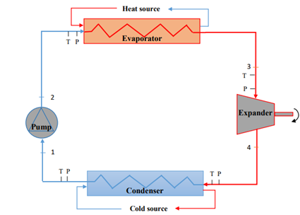
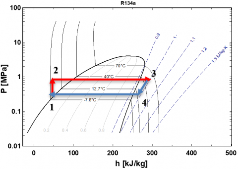
An evaporator, an expander, a condenser, and a pump make up the organic Rankine cycle system under investigation. Condenser and evaporator were of the counter-flow shell and tube kind. Figure 1 shows a schematic representation of the ORC system. The fluid goes from point 1 to point 2 of the pump, where it is pumped to high pressure and then into the evaporator, where it is heated and evaporated through the heat exchanger. The superheated liquid from the evaporator's high-pressure point 3 goes into the expander, where the enthalpy created by the shaft movement is transformed into energy. The low-pressure liquid at point 4 is driven into the condenser, where it is condensed by the water, restarting the cycle. As shown in Figure 2, temperature-sensitive and pressure measurements were put at each component's entrance. A P-h diagram depicts the above processes. Table 1 lists the criteria for the simulation parameters for the ORC model.
Figure 1. Simple configuration of ORC
Figure 2. P-h diagram in superheated ORC
Table 1. Specifications of the ORC conditions
|
Parameter |
Value |
Unit |
|
Superheated temperature range |
55-85 |
℃ |
|
Evaporator pressure range |
0.4-0.6 |
MPa |
|
Condenser pressure |
0.38 |
MPa |
|
Ambient temperature |
15 |
℃ |
|
Ambient pressure |
0.1015 |
MPa |
|
The expander’s isentropic efficiency |
85% |
- |
|
Isentropic efficiency of the pump |
80% |
- |
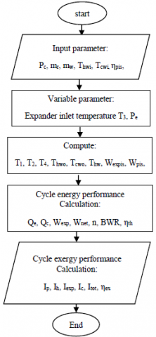
The first and second principles of thermodynamics are used to evaluate performance. To find the optimum operating condition that increases thermal efficiency while minimizing the risk of irreversible equipment damage, pressures and temperatures affect system working conditions. The process model was created using the Engineering Equation Solution (EES). Therefore, the following equations were presented to determine the irreversibility and efficiency of the cycle. The hypotheses are put in this paper: Steady-state conditions, neglecting the pressure drop in the evaporator, condenser and pipelines, As well as kinetic and potential energy losses across all components and tubes. To perform ORC simulation, EES simulation software is used. An overall approach, which is schematically depicted in Figure 3, was developed using all model equations.
Figure 3. Flow chart of the simulation procedure
This equation may be used for any control volume in steady state with little kinetic or potential energy change to represented the balances of mass, energy and exergy, respectively, by [18]:
$\sum \dot{m}_{\mathrm{i}}=\sum \dot{m}_{\mathrm{o}}$ (1)
$\mathrm{Q}+\mathrm{W}=\sum \mathrm{m}_{\mathrm{i}} \mathrm{h}_{\mathrm{i}}-\sum \mathrm{m}_{\mathrm{o}} \mathrm{h}_{\mathrm{o}}$ for energy analysis (2)
The exergy balance refers to difference between the net exergy transfer over the system border and the exergy destroyed inside the system boundaries as a result of irreversibilities in a system exergy change throughout a process.
$\mathrm{E}_{\text {heat }}+\mathrm{W}=\sum \dot{\mathrm{m}}_{\mathrm{i}} \mathrm{e}_{\mathrm{i}}-\sum \dot{\mathrm{m}}_{\mathrm{o}} \mathrm{e}_{\mathrm{o}}+\mathrm{I}$ for exergy analysis (3)
where: $\mathrm{e}=\left(\mathrm{h}-\mathrm{h}_{\mathrm{o}}\right)-\mathrm{T}_{\mathrm{o}}\left(\mathrm{s}-\mathrm{s}_{\mathrm{o}}\right)$.
$\mathrm{I}=\sum \dot{\mathrm{m}}_{\mathrm{i}} \mathrm{e}_{\mathrm{i}}-\sum \dot{\mathrm{m}}_{\mathrm{o}} \mathrm{e}_{\mathrm{o}}+\left(\sum\left(\mathrm{Q}_{\mathrm{i}}\left(1-\frac{\mathrm{T}_{0}}{\mathrm{~T}}\right)\right)-\left(\sum \mathrm{Q}_{\mathrm{o}}\left(1-\frac{\mathrm{T}_{0}}{\mathrm{~T}}\right)\right)+\mathrm{W}\right.$ (4)
I that which is lost in the cycle is called exergy or the irreversibility. The exergy of the control volume’s input and outflow streams is represented first two terms on the right side of the equation. In terms of the exergy, third and fourth terms refers to the heat transmitted from a temperature-controlled source. If solution and refrigerant pumps are included, the exergy of mechanical work contributed to the control volume is insignificant.
The following introduces the equations to perform the comparative thermodynamic analysis.
Energy analyses equation [19, 20].
3.1 Evaporator or heat exchanger
Helical coil shells and tube type heat exchangers make up the entire system because of the advantages of compactness and efficient heat transfer they provide.
$\mathrm{Q}_{\mathrm{e}}=\dot{\mathrm{m}}_{\mathrm{r}}\left(\mathrm{h}_{3}-\mathrm{h}_{2}\right)=\dot{\mathrm{m}}_{\mathrm{w}} \mathrm{cp}\left(\mathrm{T}_{\mathrm{hwi}}-\mathrm{T}_{\mathrm{hwo}}\right)$ (5)
Condenser
$\mathrm{Q}_{\mathrm{c}}=\mathrm{m}_{\mathrm{r}}\left(\mathrm{h}_{3}-\mathrm{h}_{2}\right)=\dot{\mathrm{m}}_{\mathrm{w}} \mathrm{cp}\left(\mathrm{T}_{\mathrm{cwo}}-\mathrm{T}_{\mathrm{cwi}}\right)$ (6)
3.2 Expander
The evaporator absorbed energy, which the expander then converts into mechanical work that may be put to good use.
$\mathrm{W}_{\text {exp. }}=\mathrm{m}_{\mathrm{r}}\left(\mathrm{h}_{3}-\mathrm{h}_{4}\right) * \eta_{\exp }=\mathrm{m}_{\mathrm{r}}\left(\mathrm{h}_{3 \mathrm{~s}}-\mathrm{h}_{4}\right)$ (7)
Refrigerant pump
$\mathrm{W}_{\mathrm{p}}=\mathrm{m}_{\mathrm{r}}\left(\mathrm{h}_{2}-\mathrm{h}_{1}\right) * \eta_{\mathrm{p}}=\mathrm{m}_{\mathrm{r}}\left(\mathrm{h}_{2 \mathrm{~s}}-\mathrm{h}_{1}\right)$ (8)
Thermal efficiency is defined as follows:
$\eta_{t h}=\frac{W_{\text {net }}}{Q_{e}}$ (9)
where: $W_{\text {net }}=W_{\text {exp. }}-W_{p}$.
Exergy destruction or irreversibility rate analyses equation [21].
Most of the ORC system’s thermodynamic irreversibility is due to losses caused by heat transfer that cannot be recovered and losses to ambient air. Irreversibility is impossible in all natural processes. Reversibility arises from the fact that, in any sufficiently complex system, the composition or arrangement of the atoms and molecules will change in an unforeseen fashion when the system is taken from one thermodynamic state to another. In order to transition from one state to another, the molecules in the "working body" interact with one another. when they transition from one state to another. friction and collisions cause some thermal energy losses during this process. A reversal of the process will obliterate any remaining energy in the system [22].
The irreversibility rate of a thermodynamic system's operations affects its performance significantly. In a real process, internal or external factors are the primary causes of entropy creation. Internal entropy is produced by I pressure drop in system-related pipes owing to friction, (ii) uncontrolled expansions in the turbine, and (iii) internal energy transfer over a restricted temperature difference in the components. Mechanical work transmission and heat transfer across constrained temperature fluctuations can both create external entropy. This refers to the principle of the second law of thermodynamics [23].
The evaporator irreversibility rate may be calculated using Eq. (4):
$\mathrm{I}_{\mathrm{h}}=\mathrm{T}_{0} \mathrm{~m}_{\mathrm{r}}\left(\left(\mathrm{s}_{3}-\mathrm{s}_{2}\right)-\frac{\left(\mathrm{h}_{3}-\mathrm{h}_{2}\right)}{\mathrm{T}_{\mathrm{H}}}\right)$ (10)
The irreversibility rate of an expander may be calculated as follows:
$\mathrm{I}_{\text {exp. }}=\mathrm{T}_{0} \mathrm{~m}_{\mathrm{r}}\left(\mathrm{s}_{4}-\mathrm{s}_{3}\right)$ (11)
Eq. (4) may be used to calculate the condenser irreversibility rate.
$\mathrm{I}_{\mathrm{c}}=\mathrm{T}_{0} \mathrm{~m}_{\mathrm{r}}\left(\left(\mathrm{s}_{1}-\mathrm{s}_{4}\right)-\frac{\left(\mathrm{h}_{1}-\mathrm{h}_{4}\right)}{\mathrm{T}_{\mathrm{L}}}\right)$ (12)
The irreversibility rate for the pump is:
$\mathrm{I}_{\mathrm{p}}=\mathrm{T}_{0} \mathrm{~m}_{\mathrm{r}}\left(\mathrm{s}_{2}-\mathrm{s}_{1}\right)$ (13)
Eqns. (10), (11), (12), and (13) may be used to calculate total irreversibility as follows:
$\mathrm{I}_{\text {tot }}=\mathrm{I}_{\mathrm{h}}+\mathrm{I}_{\text {exp. }}+\mathrm{I}_{\mathrm{c}}+\mathrm{I}_{\mathrm{p}}$ (14)
Second law efficiency or exergy efficiency
$\eta_{\mathrm{ex}}=\frac{\eta_{\mathrm{th}}}{\left(1-\frac{\mathrm{T}_{0}}{\mathrm{~T}_{\mathrm{hw}}}\right)}$ (15)
where: $\mathrm{T}_{\mathrm{hw}}=\frac{\mathrm{T}_{\mathrm{hwo}}+\mathrm{T}_{\mathrm{hwi}}}{2}$.
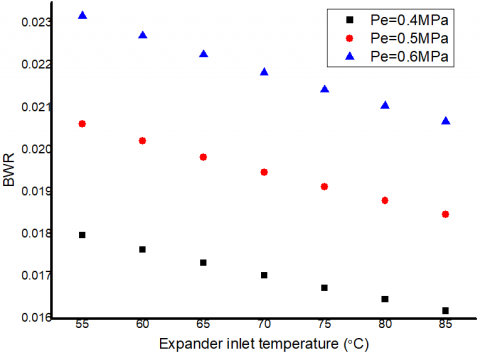
In theory, calculating the pump’s energy consumption has a lower percentage when compared with the energy produced (the energy produced by the expander). In order to know the resulting energy consumed by the pump in the system [15], the back work ratio (BWR) is a ratio between the energy consumed by the pump and the energy produced.
$\mathrm{BWR}=\frac{\mathrm{W}_{\mathrm{p}}}{\mathrm{W}_{\text {exp. }}}$ (16)
For calculate the expander rotational speed [24] by the equation:
$\mathrm{n}=\frac{\mathrm{W}_{\mathrm{exp}} \quad * 60}{\mathrm{~V}* \rho *\left(\mathrm{~h}_{3}-\mathrm{h}_{4}\right)}$ (17)
where: $\mathrm{V}=4 * \pi * \mathrm{R} * \mathrm{H} * \mathrm{~L}$.
The choice of a suitable working fluid can have a considerable impact on the thermodynamic design and performance of an ORC system. Low Ozone Depletion Potential (ODP), low GWP (Global Warming Potential), and high latent heat are just a few of the characteristics that make a working fluid suitable [25]. The optimal working fluid is chosen based on the slope of the saturation vapor line. Working fluids are classified as moist, dry, or isentropic. Dry, homogeneous fluids aid expanders because they depart as superheated steam, avoiding liquid droplets injuring turbine blades. In ORC systems, moist fluids must be more superheated heat exchangers in order to enter the expander as superheated steam. R134a was chosen as the operating fluid. The boiling point, critical pressure, and molecular weight of the fluid in an ORC all have an impact on the system's efficiency, which is defined by its standard boiling point. Physical parameters of the organic fluid are shown in Table 2.
The ORC's working fluid must have a high critical temperature, a higher saturation pressure at the condenser than atmospheric pressure, a low specific heat freezing temperature below room temperature, be chemically stable, nontoxic, and noncorrosive, not excessively viscous, and be inexpensive. These qualities are necessary for the fluid to be economically feasible, ecologically beneficial, and safe for both materials and humans [23]. The specifics can be found in prior works [10]. The fluid used in this investigation was selected based on the criteria stated above. As a working fluid for an ORC, this study was conducted [23].
Table 2. Physical properties, safety and environmental data of the organic fluid used [26]
|
Chemical formula |
CH2FCF3 |
|
Simple |
R134a |
|
Tc (℃) |
101.1 |
|
Pc (MPa) |
4.06 |
|
Molecular mass (kg. kmol-1) |
102.03 |
|
ODP |
0 |
|
GWP |
1430 |
|
Type |
Wet |
|
Flammability/Toxicity |
No |
The ORC system was subjected to a thermodynamic analysis based on the first and second thermodynamic principles. The energy, exergy, and mass flow rate balance equations were operated in steady-state on the system's components. The EES software tool was used to compute the fluid's energy, exergy, thermal efficiency, BWR, rotational speed, and irreversibility. At 0.38 MPa, the pressure of condensation remains constant. The performance of ORC was investigated for the working fluid at three different evaporator pressure conditions: 0.4, 0.5 and 0.6 MPa, with the expander inlet temperature at 55, 60, 65, 70, 75, 80, and 85℃.
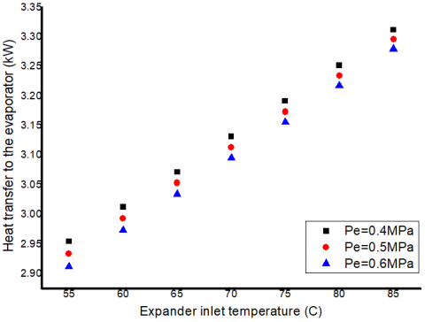
As shown in Figure 4, an increase in the temperature of superheated steam allows for an increase in heat transfer in the evaporator. This indicates that less time is required from the heat source. Where the amount of thermal energy is determined by the duration of the interaction of the working fluid with the heat source when the pressure is constant. But with the change in pressure, the heat transfers to the evaporator decreases due to the decrease in enthalpy. So it is affected by heat exchange between the liquid used and the hot water.
As may be seen in Figure 4, as the temperature rises, the heat transfers between the fluid and the heat source temperature increases. As a result, the greater the evaporator's heating temperature and heat transfer, the higher the efficiency a little. The change in enthalpy in different instances is the cause of the reduction in heat transfer with increased pressure. On the other hand, at high pressures, the quantity of evaporation heat is reduced. As the expander's intake temperatures rise at varying evaporation pressures, the efficiency rises. The efficiency of the evaporator improves practically linearly with the intake temperature and heat transfer of the evaporator.
Figure 4. The heat transfers against the expander inlet temperature at superheated point for R134a
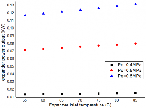
The effects of expander inlet pressure on net power vary, as seen in Figure 5. When the expander's inlet temperature is 55℃, the expander's net power rises as the inlet pressure rises. Increased expander inlet pressure equals more net power production. The expander's inlet temperature may be raised to enhance the expander's net power production while also raising the inlet pressure.
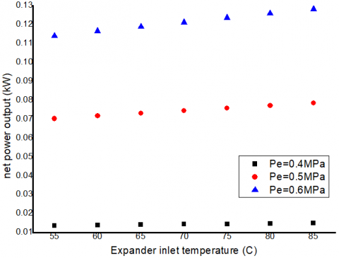
Figure 6 depicts the variations in net power production as a function of the expander's input pressure and temperature. Increasing the inlet temperature of the expander increases the enthalpy rise across the expander. Because the evaporation temperature is changing but the pressure remains constant, the higher the input temperature, the greater the enthalpy difference. When the expander's enthalpy is increased, the net power production rises since the pump's consumption capacity remains constant at different temperatures.
Figure 6 shows the effect of the inlet temperature of the expander on the Wnet. The power output increases with the increasing inlet temperature of the expander, and there is no maximum value for Wnet. So the power output ranges between 0.1167 - 0.1309 kW at the same pressure of 0.6 MPa. When the minimum working output is between 0.01369 - 0.01521 kW, the minimum pressure is 0.4 MPa. The working fluid achieved the highest values of Wnet at the highest pressure and highest inlet temperature of the expander, at 85℃.
Figure 5. Effect of expander inlet temperature on expander work output at evaporator different pressures
Figure 6. Expander inlet temperature effects on Work output at constant condensation temperature
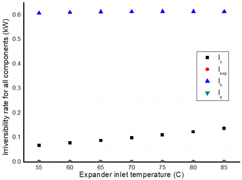
Figure 7. The irreversibility with expander inlet temperature at the highest evaporating pressure of 0.6 MPa
Figure 7 represents the irreversibility with the expander inlet temperature increased at the highest evaporating pressure of 0.6 MPa. At 85℃, the irreversibility of the evaporator is the highest compared to the expander, pump, and condenser. While the condenser also increased, the pump and expander remained constant with the increase in the expander inlet temperature. The increase in the condenser and evaporator is because of the exchange between the heat source and the working fluid. So, the increase in irreversibility in the two terms for connecting the exchanger heat. The constant irreversibility of the pump and expander means they do not connect to the heat. Irreversibility is represented by Eqns. (10) to (13).
Exergy destruction or irreversibility distribution investigation revealed that the evaporator is responsible for 0.6132 kW of irreversibility, the expander for 0.002168 kW, the condenser for 0.1369 kW, and the pump for 0.00005052 kW. For the high pressure of 0.6 MPa and the expander inlet temperature of 85℃, the distribution is practically the same. The exergy in the evaporator and condenser is destroyed as a result of these results owing to the temperature differential between the hot water entering and exiting the component. Further improvements can be made by carefully designing the evaporator, which necessitates a wide heat exchange surface.
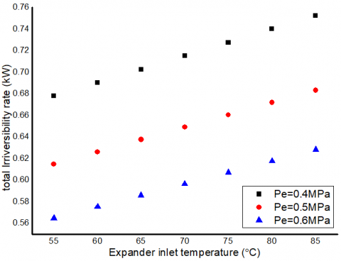
Figure 8 shows how total system irreversibility changes with expander inlet temperature and pressure under the same conditions that were used to obtain the results indicated in Figure 11. The total irreversibility of the system is immediately affected by increasing the expander inlet temperature at all pressures for the Eq. (14). The results in this graph demonstrate the need of doing a second review of the law. The thermal efficiency of the expander remains almost constant when the input temperature is increased, as seen in Figure 11.
Figure 8. The effect of expander inlet temperature on irreversibility at evaporator different pressures
Figure 9. Effect of expander inlet temperature on BWR at evaporator different pressures
The illustration in Figure 9 shows the effect of the back work ratio BWR on the inlet temperature of the expander at different pressures of the evaporator in Eq. (16). When the expander's inlet temperature rises, BWR drops. As previously shown in Figure 11, the lower the back working ratio, the better, and so impacts thermal efficiency. As a result, the better the thermal efficiency, the lower the BWR. The BWR, on the other hand, is the smallest at 0.4 MPa. At inlet temperatures of the expander of 55, 60, 65, 70, 75, 80, and 85 °C, the BWR varies from 0.01797 to 0.01618. The maximum BWR, ranging from 0.02318 to 0.02068, is attained at the highest pressure of 0.6 MPa, which is undesired due to its influence on thermal efficiency. At constant temperatures, the drop in BWR is attributable to a rise in the expander's power output and work pump usage.
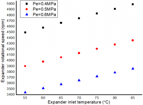
The influence of the expander's rotational speed on the expander inlet temperature at varying evaporator pressures is seen in Figure 10. As seen in Eq. (17), the rotating speed increases as the temperature of the expander's input rises. As a result, the rise is attributed to an increase in the expander's work output. As a result, the faster the spin, the more work there is.
At the lowest pressure of the evaporator, 0.4 MPa, the greatest rotational speed is reached, resulting in a speed range of 4496-4993 rpm at temperatures of the expander inlet of 55-85℃. The decrease in the density of the working fluid R134a also contributes to the rise in speed. Because the temperature of the fluid rises as it approaches the expander. The density of R134a falls as the humidity decreases, and the R134a is in a highly hot condition and only exists in the gas phase. The lowest speed was achieved while at the greatest pressure of 0.6 MPa. The speed varies between 3440 and 3858 rpm due to an increase in density, which causes the speed to drop.
Figure 10. Effect of the expander inlet temperature on rotational speed at evaporator different pressures
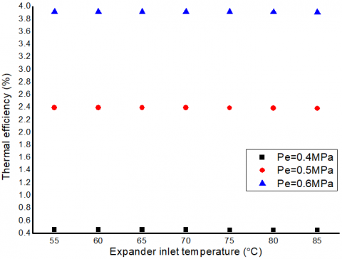
Figure 11. The thermal efficiency with the increase of expander inlet temperature at superheated for R134a at different pressure
Figure 11 shows the system's thermal efficiency variation as a function of inlet temperature and pressure, as given in Eq. (9). As a result of the superheating of the working fluid, the cycle's thermal efficiency is illustrated in the graph. The cycle efficiency remains almost constant as the expander's intake temperature rises. The organic fluid used in this cycle does not require warming to increase its overall performance because of its low temperature requirements.
R134a has the maximum efficiency at the highest pressure and the lowest efficiency at the lowest pressure, as seen in Figure 11. As a consequence, it works best at temperatures ranging from 55 to 85 degrees Celsius. Organic liquid, as a remainder, may be used to create energy at low temperatures. Organic fluids, on the other hand, can only be employed in a few situations owing to their thermodynamic restrictions.
Figure 11 depicts how the expander inlet pressure affects the thermal efficiency of the system; thus, the results are applicable across a wide range of expander inlet pressures. This may be explained by an increase and a decrease in evaporator heat at the inlet expander pressure.
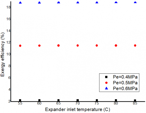
Figure 12, The exergy efficiency in Eq. (15) is shown to be affected by the evaporator pressure and inlet temperature. It is possible to notice a rise in exergy when the evaporator pressure is raised, indicating an optimum evaporator pressure level. Enthalpy differences across the expander’s inlet and outlet can be increased by increasing the pressure of its evaporator.
Figure 12 also shows the effect of expander temperature on exergy efficiency. Exergy efficiency increases as the expander inlet temperature rises, as seen in the graph. The surface area of each heat exchanger (evaporator and condenser) increases as the expander inlet temperature rises, increasing the quantity of heat exchanged between the two.
Figure 12. The exergy efficiency with the expander inlet temperature from superheated for R134a
The current study was compared with another study such as [7]. In the same design of spiral shell and tube heat exchangers, the thermal efficiency of the current study is greater than that of the previous study, although there is a slight difference between the two studies. The efficiency in the current study was 3.907% at the pressure of the expander and pump, which was 0.38 MPa and 0.4 MPa, respectively. The mass flow rate is 0.0125 kg.s-1. While the efficiency of the previous study was 3.8% at the pressure of the evaporator and pump at 0.55 MPa and 0.79 MPa, respectively, 0.123 kg.s-1 mass flow rate It is noted that the current efficiency is greater, although the mass flow rate is lower compared to the previous study. The reason is due to the fact that the temperature enters the expander when the temperature rises and ensures the entry of superheated steam without any moisture or mixture of the used R134a. The reason for the decrease in mass flow rate is the effect of pressure.
The performance of ORC employing R134a is examined in this research. thermal efficiency, exergy efficiency, irreversibility, expander work output, back pump work ratio and rotational speed at different evaporator pressures of 0.4, 0.5 and 0.6 MPa was studied. It was shown that organic fluid can be used to generate power using low temperatures. These is temperatures ranging from 55℃, 60℃, 65℃, 70℃, 75℃, 80℃, and 85℃. When the pressure of the expander increases, it improves the cycle efficiency, the irreversibility increases, and the output power increases. which leads to better work under operating conditions at a pressure of 0.6 MPa and a higher temperature of 85℃. The best theoretical results at constant evaporator pressure of 0.6 MPa with increasing temperature result in a decrease in the thermal efficiency of 3.914%-3.907%. The effect of increasing the thermal efficiency from 0.4518%-3.907% at the highest inlet temperature of 85℃ and expander pressures of 0.4, 0.5 and 0.6 MPa at constant evaporator temperature. Constant evaporator pressure of 0.6 MPa, increasing the temperature results in increasing the exergy efficiency from 18.81%-18.89%. and at constant evaporator temperature, the effect of increasing the exergy efficiency from 2.185% to 18.89% at the highest inlet temperature of 85℃ and pressure of the expander between 0.4, 0.5 and 0.6 MPa. The highest rotational speed that was obtained at a minimum pressure of 0.4 MPa and a temperature of 85℃ was 4993 rpm.
The organic fluid R134a does not require superheating since the cycle thermal efficiency remains relatively constant or little slows down as the expander input temperature rises. However, it can be demonstrated from a second law analysis that superheating organic fluid enhances irreversibility. To lessen the system's entire irreversibility, the organic fluid must be operated under saturated conditions.
|
Cp |
Heat transfer coefficient at constant water pressure, J. kg-1. ºC-1 |
|
e |
specific exergy destruction rate |
|
H |
eccentricity, 0.0014 m |
|
I |
irreversibility or exergy destruction rate |
|
L |
cylinder length, 0.0382 m |
|
ṁ |
Mass flow rate, kg. s-1 |
|
N |
Rotational speed, rpm |
|
R |
cylinder radius, 0.016 m |
|
ORC |
Organic Rankine cycle |
|
P |
Pressure, Mpa |
|
Q |
Heat transfer rate, W |
|
T |
Temperature, ºC |
|
W |
Power, W |
|
Greek symbols |
|
|
$\eta_{\mathrm{th}}$ |
Thermal efficiency |
|
$\eta_{\mathrm{ex}}$ |
Exergy efficiency |
|
ρ |
Density, kg.m-3 |
|
Subscripts |
|
|
c |
Condenser |
|
exp |
Expander |
|
e |
Evaporator |
|
i |
Inlet |
|
o |
Outlet |
|
V |
Displacement Volume, m3/rev |
|
r |
Refrigerant |
|
w |
Water |
|
0 |
Ambient |
|
hw |
Hot water |
|
cw |
Cold water |
|
p |
pump |
|
tot |
total |
|
H |
high |
|
L |
low |
|
net |
network |
[1] Tartière, T., Astolfi, M. (2017). A world overview of the organic Rankine cycle market. Energy Procedia, 129: 2-9. https://doi.org/10.1016/j.egypro.2017.09.159
[2] Montenegro, G., Torre, A.D., Onorati, A., Broggi, D. (2014). CFD simulation of a sliding vane expander operating inside a small scale orc for low temperature waste heat recovery. SAE Technical Papers 1. https://doi.org/10.4271/2014-01-0645
[3] Quoilin, S., Lemort, V., Lebrun, J. (2010). Experimental study and modeling of an Organic Rankine Cycle using scroll expander. Appl. Energy, 87(4): 1260-1268. https://doi.org/10.1016/j.apenergy.2009.06.026
[4] Kalinci, Y., Hepbasli, A., Dincer, I. (2014). Exergetic performance assessment of a binary geothermal power plant. Springer, 23-32. https://doi.org/10.1007/978-3-319-04681-5
[5] Awaludin, M., Nur, M. (2021). Experimental investigation of a 560 watt organic rankine cycle system using R134a as working fluid and plat solar collector as heat source. IJEEPSE, 4(3): 169-172.
[6] Colak, L., Bahadir, T. (2016). Modeling thermodynamic analysis and simulation of organic rankine cycle using geothermal energy as heat source. 12th Int. Conf. Heat Transf. Fluid Mech. Thermodyn., pp. 1502-1508.
[7] Martin, A., Romy, Agustina, D., Ibra, A.M. (2019). Design and manufacturing of organic rankine cycle (orc) system using working fluid r-134a with helical evaporator and condenser. IOP Conf. Ser. Mater. Sci. Eng., 539: 012027. https://doi.org/10.1088/1757-899X/539/1/012027
[8] Wang, L., Bu, X., Li, H. (2020). Multi-objective optimization and off-design evaluation of organic rankine cycle (ORC) for low-grade waste heat recovery. Energy, 203: 117809. https://doi.org/10.1016/j.energy.2020.117809
[9] Wang, J.L., Zhao, L., Wang, X.D. (2010). A comparative study of pure and zeotropic mixtures in low-temperature solar Rankine cycle. Appl. Energy, 87(11): 3366-3373. https://doi.org/10.1016/j.apenergy.2010.05.016
[10] Vélez, F., Chejne, F., Quijano, A. (2014). Thermodynamic analysis of R134a in an Organic Rankine Cycle for power generation from low temperature sources. DYNA, 81(185): 153-159. https://doi.org/10.15446/dyna.v81n185.37598
[11] Pethurajan, V., Sivan, S. (2018). Experimental study of an organic Rankine cycle using n-hexane as the working fluid and a radial turbine expander. Inventions, 3(2): 31. https://doi.org/10.3390/inventions3020031
[12] Kolasiński, P. (2019). Application of the multi-vane expanders in ORC systems - A review on the experimental and modeling research activities. Energies, 12(15): 2975. https://doi.org/10.3390/en12152975
[13] Martin, A., Naibaho, C., Kurniawan, I. (2019). Design and manufacturing of organic Rankine cycle (ORC) system using R-134a as working fluid with solar collector as source energy. International Conference of CELSciTech 2019-Science and Technology track (ICCELST-ST 2019), pp. 38-43. https://doi.org/10.2991/iccelst-st-19.2019.8
[14] Fatigati, F., Di Bartolomeo, M., Di Battista, D., Cipollone, R. (2019). Experimental characterization of a hermetic scroll expander operating in an ORC- based power unit bottoming an internal combustion engine. AIP Conf. Proc., 2191(1): 1-10. https://doi.org/10.1063/1.5138802
[15] Hartulistiyoso, E., Sucahyo, L., Yulianto, M., Sipahutar, M. (2020). Thermal efficiency analysis of Organic Rankine Cycle (ORC) System from low-grade heat resources using various working fluids based on simulation. IOP Conf. Ser. Earth Environ. Sci., 542: 012047. https://doi.org/10.1088/1755-1315/542/1/012047
[16] Abd Al-kareem, A.H., Al-Hamadani, A.A.F. (2020). Experimental study of Organic Rankine cycle system by using R141b as working fluid. Wasit J. Eng. Sci., 8(1): 21-30. https://doi.org/10.31185/ejuow.Vol8.Iss1.152
[17] Prasetyo, T., Surindra, M.D., Caesarendra, W., Glowacz, T.A., Irfan, M., Glowacz, W. (2020). Influence of superheated vapour in organic rankine cycles with working fluid R123 utilizing low-temperature geothermal resources. Symmetry (Basel)., 12(9): 1463. https://doi.org/10.3390/sym12091463
[18] Çengel, Y.A., Boles, M.A. (2015). Thermodynamics an Engineering Approach. Eighth Edition. McGraw-Hill Education
[19] Nouman, J. (2012). Comparative studies and analyses of working fluids for Organic Rankine Cycles - ORC. Master of Science Thesis, KTH School of Industrial Engineering and Management.
[20] Koç, Y., Yaglı, H., Koç, A. (2019). Exergy analysis and performance improvement of a subcritical / supercritical organic Rankine cycle (ORC) for exhaust gas waste heat recovery in a biogas fuelled combined heat and power (CHP) engine through the use of regeneration. Energies, 12(4): 575. https://doi.org/10.3390/en12040575
[21] Zhang, S.J., Wang, H.X., Guo, T. (2011). Performance comparison and parametric optimization of subcritical Organic Rankine Cycle (ORC) and transcritical power cycle system for low-temperature geothermal power generation. Appl. Energy, 88(8): 2740-2754. https://doi.org/10.1016/j.apenergy.2011.02.034
[22] Costa, T., Zarante, P., Sodré, J. (2013). Simulation of Aldehyde Formation in Ethanol Fuelled Spark Ignition Engines. In: Sens, M., Baar, R. (eds) Engine Processes. Expert Verlag, Berlin.
[23] Roy, J.P., Misra, A. (2017). Comparative performance study of different configurations of organic Rankine cycle using low-grade waste heat for power generation. International Journal of Green Energy, 14(2): 212-228. https://doi.org/10.1080/15435075.2016.1253570
[24] Kolasiński, P. (2015). The influence of the heat source temperature on the Multivane expander output power in an Organic Rankine Cycle (ORC) system. Energies, 8(5): 3351-3369. https://doi.org/10.3390/en8053351
[25] Kumar, A., Shukla, S.K. (2016). Analysis and performance of ORC based solar thermal power plant using benzene as a working fluid. Procedia Technol., 23: 454–463. https://doi.org/10.1016/j.protcy.2016.03.050
[26] Calm, J.M., Hourahan, G.C. (2007). Refrigerant data update. HPAC Heating, Piping, Air Conditioning Eng., 79(1): 50-64.