Hugo Fuentes | Alvaro Valencia*
© 2022 IIETA. This article is published by IIETA and is licensed under the CC BY 4.0 license (http://creativecommons.org/licenses/by/4.0/).
OPEN ACCESS
Longitudinal vortex generators (LVG) over the last decades have been investigated to enhance heat transfer in rectangular channels with different design to obtain high thermal performance (TEF). In this investigation, the shear-stress transport (SST) k-ε model is used to model the turbulence. The turbulent flow and heat transfer, using delta wing (DW), delta winglet pair (DWP), DWP inclined (DWPI) and rectangular winglet pair curved (RWPC) was compared in a rectangular channel. The best TEF by 1.26 was obtained using DW for Reynolds number of 2800. The DW is a simple to manufacture LVG, and the TEF is only a little lower compared to other new, complex to manufacture, conic type LVG recently found in the literature.
turbulent flow, rectangular channel, longitudinal vortex generator, delta wing, delta winglet pair, rectangular winglet pair curved, thermal performance
Air flow in a rectangular channel are used in several industrial applications like compact heat exchanger, air conditioning system, food processing system, aeronautics, among many other applications. In the most applications, the air flow is turbulent between the plane walls, however the air thermal resistance is high. This limitation has motivated a large amount of investigations to enhance the heat transfer on the air side. Wavy, louvered, and slit fins have been used to reduce the air thermal resistance in the channel compared with the plane walls [1].
In the las decades longitudinal vortex generators (LVG) have been investigated as a way of increasing the heat transfer rate in air channels. LVG are protrusions from a surface that intensify the heat transfer interrupting boundary layers, developing longitudinal vortices, mixing flow and causing flow destabilization on the air side, that remains over long distances in the flow channel [2]. The angle of attack, aspect ratio and LVG design have a significant effect on heat transfer enhancement and increase in pressure drop [3]. Most investigations were made by plane channel with laminar flow or by plane fins and tube compact heat exchangers; the present research is concentrated by turbulent flow in a rectangular channel without cylinders.
Delta wing (DW), rectangular wing (RW), delta winglet pair (DWP), rectangular winglet pair (RWP) have been compared for turbulent Reynolds number, and for angles of attack between 30° and 90° by Tiggelbeck et al. [4] in a channel flow experimentally using liquid crystal thermography. Delta winglet pair perform better performance and can enhance the heat transfer by 120% at Re=8000. The influences of the four types of LGV was numerical investigated by Zhu et al. [5] by turbulent flow with higher Reynolds number in a channel flow. The mean heat transfer rate was increases by 19% with the DWP by an area of channel 30 times larger than the LVG area; however, the increase in pressure loss was 4.2 larger compared with the channel without LVG.
Using a DW in a turbulent flow in a rectangular channel including natural convection, Garelli et al. [6] obtained that the overall heat transfer improves by 12%, they used DW with an angle of attack of 30°, they conclude that the TEF depends of the area influenced by the LGV and the reference area of the channel.
Oneissi et al. [7] introduced inclined DWP, the local performance was analyzed in a rectangular channel by turbulent flow, the DWPI produces similar heat transfer enhancement compared with the DWP, but the pressure increase was lower due the special aerodynamic design.
Concave, convex and plane LVG was compared by Song et al. [8] in a plane channel by laminar flow, the concave curved delta winglet LVG has large heat transfer enhancement and pressure drop increases compared with the plane winglet and higher thermal performance, convex LVG showed lower thermal performance compared with plane LVG.
LVG with a hole can improve the heat transfer and reduce the pressure drop compared with the LVG without holes, by turbulent flow in a rectangular channel according to Lu and Zhuo [9]. Curved trapezoidal winglet pair with a hole give the high thermal performance compared with delta winglet and rectangular winglet pairs.
Combined delta winglet insert in laminar regime was reported by Liu et al. [10]. The combined LVG include three winglets, the thermal performance depends on rotation angle and spacing between the winglets. The effects on Nusselt number and friction factor of secondary wing in a rectangular winglet pair, was investigated in Ref. [11], the effects of the secondary wing were not relevant.
A novel type of LVG was experimentally studied by Dogan and Abir [12], the performance was compared with delta winglet pairs, in a rectangular channel for turbulent flow. The novel LVG consist in a curved delta wing. The novel LVG is complex to introduce in a rectangular channel due a small part are insert on the wall. The TEF of the novel LVG war larger compared with a DWP. Other new type conic LVG was numerically investigated by Zahit et al. [13] in a rectangular channel by turbulent flow. The thermal performance was higher than the DWP. The form of this new LVG is a delta wing type but with a complex geometry based in a conic surface and a plane wing with two parts like an airplane wing.
The purpose of this research is to compare simple and classical wing with delta winglet, inclined delta winglet and curved rectangular winglet in turbulent regime to find a high thermal performance with a minimal manufacture complexity. We hypothesize that wing LVG must be compared with one winglet and not with a winglet pair as in the previous investigations. In spite of the large number of previous results on the effects of LVG in channels, this comparison of the basic geometry has not yet performed, and motivated this project.
2.1 Governing equations
The governing equations are the continuity, momentum and energy equation. Air is assumed incompressible with constant properties. The incompressible Newtonian fluid flow is governed by averaged Navier-Stokes (RANS) equations.
Continuity equation
$\frac{\partial u_{i}}{\partial x_{i}}=0$ (1)
Momentum equations
$\rho\left(\frac{\partial u_{i}}{\partial t}+u_{j} \frac{\partial u_{i}}{\partial x_{j}}\right)=-\frac{\partial P}{\partial x_{i}}+\mu\left(\frac{\partial^{2} u_{i}}{\partial x_{j} x_{i}}\right)-\frac{\partial \overline{u_{i}^{\prime} u_{j}^{\prime}}}{\partial x_{j}}$ (2)
Energy equation
$\rho c_{p}\left(\frac{\partial T}{\partial t}+u_{i} \frac{\partial T}{\partial x_{i}}\right)=\frac{\partial}{\partial x_{i}}\left(k_{e f f} \frac{\partial T}{\partial x_{i}}\right)$ (3)
where,
$u_{i}\left[\frac{\mathrm{m}}{\mathrm{s}}\right], \rho\left[\frac{\mathrm{kg}}{\mathrm{m}^{3}}\right], t[s], P[\mathrm{~Pa}], \mu\left[\frac{\mathrm{Ns}}{\mathrm{m}^{2}}\right], c_{p}\left[\frac{\mathrm{kJ}}{\mathrm{kgK}}\right], k_{\text {eff }}\left[\frac{\mathrm{W}}{\mathrm{mK}}\right]$ represent the velocity, density, time, pressure, dynamic viscosity, specific heat and effective thermal conductivity, respectively.
The SST-k-ω transport model are:
$\rho \frac{\partial}{\partial x_{i}}\left(\frac{\partial k}{\partial t}+k u_{i}\right)=\frac{\partial}{\partial x_{j}}\left(\Gamma_{k} \frac{\partial k}{\partial x_{j}}\right)+G_{k}-Y_{k}$ (4)
$\rho \frac{\partial}{\partial x_{i}}\left(\frac{\partial \omega}{\partial t}+\omega u_{i}\right)=\frac{\partial}{\partial x_{j}}\left(\Gamma_{\omega} \frac{\partial \omega}{\partial x_{j}}\right)+G_{\omega}-Y_{\omega}+D_{\omega}$ (5)
where, $\mathrm{G}_{\mathrm{k}}$ and $\mathrm{G}_{\mathrm{\omega}}$ are the production of turbulent kinetic energy $\mathrm{k}$ and the dissipation $\omega, \Gamma_{k}$ and $\Gamma_{\omega}$ are the effective diffusivity of $\mathrm{k}$ and $\omega$, respectively, $\mathrm{Y}_{\mathrm{k}}$ and $\mathrm{Y}_{\omega}$ are the dissipation due the turbulence of $\mathrm{k}$ and $\omega$ respectively. More details can be found in Ref. [14].
2.2 Computational domain and LVG
In this study, delta wing (DW), delta winglet pair (DWP), inclined delta winglet pair (DWPI) and rectangular winglet pair curved (RWPC) was compared in a rectangular channel. The channel dimensions were taken from Oneissi et al. [15], to have a comparison base geometry. The channel height is H=38.6 mm, the channel width is W=1.6H and the channel length is L=13H. Figure 1 shows the principal dimensions of the rectangular channel.
Figure 1. Dimensions of the rectangular channel, [mm]
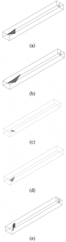
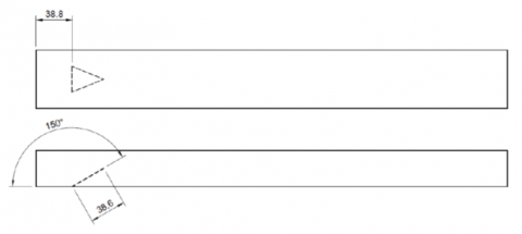
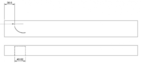
Figure 2 shows the five different investigated cases with LVG. Figure 2a shows the DWP, where only one winglet is placed in the channel. The inclined delta winglet pair (DWPI) is showed in Figure 2b, the geometry of the DWP and DWPI were taken from [15]. The delta wing DW with an attack angle of β=30° and β=150° are showed in Figures 2c and 2d, respectively, the geometry of DW was inspired by Tiggelbeck et al. [4] and Garelli et al. [6]. The rectangular winglet pair curved (RWPC) was chosen as the last geometry to compare, based in the investigations of Lu and Zhou [9].
To have the same comparison basis, the four investigated delta longitudinal vortex generators have the same frontal area. For this reason, in the cases with delta winglets pairs only one delta winglet was built in the channel wall. The pairs are generated using symmetry boundary conditions.
Figure 2. Geometry of the LVG. (a) DWP, (b) DWPI, (c) DW with β=30°, (d) DW with β=150°, (e) RWPC
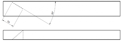
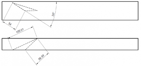
Figure 3 shows the parameters and the position in the channel of the investigated LVG geometries. The DWP and the DWPI have an attack angle of 30°. The DW have and attack angle of 30° and 150°, respectively.
(a)
(b)
(c)
(d)
(e)
Figure 3. Parameters and position of the LVG. (a) DWP, (b) DWPI, (c) DW with β=30°, (d) DW with β=150°, (e) RWPC
2.3 Boundary conditions
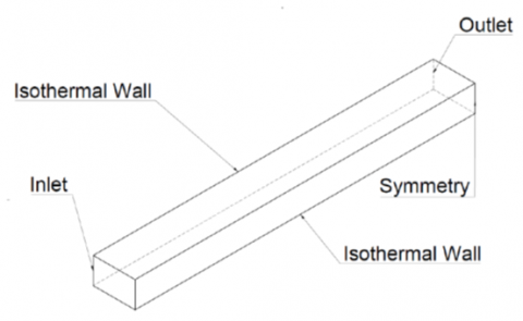
At the inlet boundary, the velocity U and the air temperature Tin are constant. For lateral boundaries, a symmetry condition was set. Outflow boundary condition was applied at the outlet region.
The computational domain and boundary conditions can be seen in Figure 4. The air inlet temperature is Tin=300 K, the channel wall temperature is set of Twall=350 K. The inlet velocity U was varied between 0.38 [m/s] to 1.52 [m/s].
Figure 4. Boundary conditions on the computational domain
2.4 Parameters
The following relevant parameter definitions will be used in this investigation. The hydraulic diameter is defined in Eq. (6), W is the channel width and H is the channel height.
$D_{H}=\frac{2 H W}{H+W} \sim 2 H$ (6)
We use this approximation of the hydraulic diameter to compare with the previously numerical and experimental investigations, [4, 7, 15].
The Reynolds number is defined by the hydraulic diameter DH and is shown in Eq. (7), and the velocity U is the inlet velocity.
$R e=\frac{\rho \cdot U \cdot D_{H}}{\mu}$ (7)
where, $\rho$ and $\mu$ represent the density $\left[\frac{\mathrm{kg}}{\mathrm{m}^{3}}\right]$ and dynamic viscosity $\left[\frac{\mathrm{kg}}{\mathrm{m} \cdot \mathrm{s}}\right]$, respectively, in this investigation $\mathrm{D}_{\mathrm{H}}=2 \mathrm{H}$.
The average temperature of air is shown in Eq. (8):
$T_{a v g}=\frac{T_{\text {in }}+T_{\text {out }}}{2}$ (8)
where, Tin is the inlet and Tout is the outlet air temperature in the channel, respectively.
The average heat transfer coefficient can be determinate using Eq. (9), as it was defined by Oneissi et al. [7, 15]:
$h=\frac{\dot{m} c_{p}\left(T_{\text {out }}-T_{i n}\right)}{A_{f}\left(T_{\text {wall }}-T_{\text {ave }}\right)}$ (9)
where, $\dot{m}$ is the air mass flow [kg/s], Af is the wall area, [m2].
The average Nusselt number is defined in Eq. (10).
$N u=\frac{h \cdot D_{H}}{k}$ (10)
To determine the friction factor (f), the pressure difference $\Delta P$ between the outlet and inlet, and the inlet velocity U are used, Eq. (11) shows the definition, where L is the channel length.
$f=\frac{\Delta P}{\rho \cdot U^{2}} \cdot \frac{H}{L}$ (11)
To measure the efficiency of the increase in heat transfer when introducing LVG in the channel, the thermal performance TEF is used, as defined in Eq. (12), Dogan and Abir [12]. The value 0 is for the channel flow without LVG, therefore, when the factor TEF is greater than one, it indicates an increase in efficiency with respect to the channel flow.
$T E F=\frac{N u / N u_{o}}{\left(f / f_{o}\right)^{1 / 3}}$ (12)
3.1 Numerical method
ANSYS 2020 [14] was used to numerically simulate the different cases; the Navier-Stokes equations were iteratively solved using the finite volume method with the COUPLED algorithm. For the turbulence, we set the shear-stress transport (SST) k-ε model. The automatic time step method was used, and the convergence criterion for every time step was residuals less than 10-3 and 10−6 for momentum and energy equations. Second order for the discretization of the equations were used. In this investigation, we use only the final solution and the setting of time step and residuals are recommended in ANSYS manual [14]. The momentum residual is lower that the energy residual, because the momentum equation requires iterations in each time step to obtain a converged solution due the pressure and velocity coupling.
3.2 Grid generation
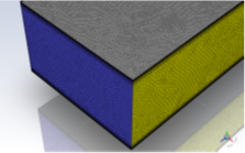
The grid was generated in two stages: non-uniform tetrahedrons elements for the complete geometry is generated. To improve the quality of the mesh system, "body sizing" was applied and we used a face sizing and an inflation of 18 layers to maintain the non-dimensional distance to wall y+ near to one. The next state is to convert the tetrahedral elements in non- uniform mesh using polyhedral elements. The conversion to polyhedral elements is useful to reduce the use of computational resources [14]. To ensure an optimal mesh, quality the orthogonal quality and skewness criteria were considered. The topology of the mesh using non-uniform polyhedral elements is displayed in Figure 5.
Figure 5. Details of the mesh using non-uniform polyhedral elements
3.3 Grid independence and validation test
The experimental results of Tiggelbeck et al. [4] were used to validate the numerical simulations. Table 1 shows the experimental results for Nusselt number and friction factor for the plane channel without LVG (Nu0, f0), and for the plane channel with a DWP (Nu, f) for Reynolds number of 4600.
Table 1. Experimental results of [4]
|
Category |
Plane channel |
DWP |
Ratio |
|
Nusselt number |
16.62 |
24.77 |
1.49 |
|
Friction factor |
0.0151 |
0.0288 |
1.91 |
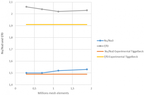
To validate the results, the geometry described in Section 2.0 for the cases without LVG and with a DWP were simulated. The heat transfer coefficient and the friction factor values for Reynolds 4600, were compared. The values obtained are shown in Table 2 and in Figure 6. Four different meshes were analyzed with 0.29, 0.70, 1.13 and 1.88 millions of elements. The results after the replication of Tiggelbeck et al. [4] study showed differences of less than 7% with the expected values using the mesh with 1.88 millions of elements, which is an acceptable difference. The mesh with 1.88 millions of elements has 66% more elements than the mesh with 1.13 millions of elements, and the difference on heat transfer and pressure low is negligible, however the computational time increase linearly with the mesh size, for this reason the mesh size was not larger than 1.88 millions of elements.
Table 2. Nusselt number and friction factor for different mesh sizes
|
Mesh siz [millions of element] |
Nu/Nu0 |
f/f0 |
|
0.29 M |
1.50 |
2.06 |
|
0.70 M |
1.50 |
2.04 |
|
1.13 M |
1.52 |
2.02 |
|
1.88 M |
1.53 |
2.03 |
Figure 6. Heat transfer coefficient and friction factor model validation
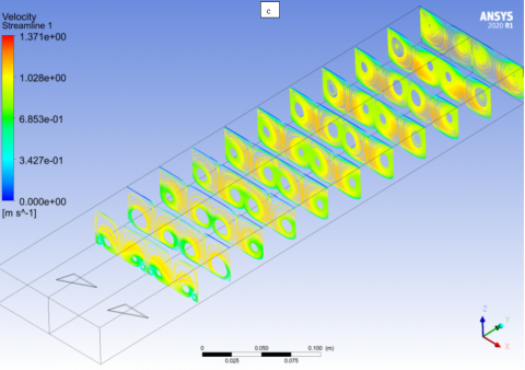
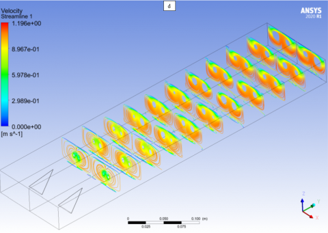
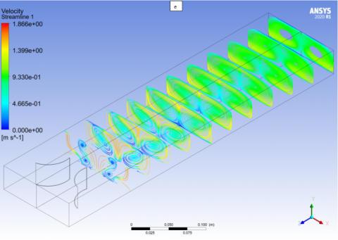
Figure 7 shows the velocity streamlines for the five investigated geometries with LVG. The figures show two computational domain to show the longitudinal vortices for the winglet pairs.
Figure 7. Velocity streamlines [m/s] for a) DWP, b) DWPI, c) DW with β=30°, d) DW with β=150°, e) RWPC, by Reynolds number Re=4600
The DWP and the DPWI generate two longitudinal vortices, and the structure of the vortices and velocity magnitude are similar in both geometries, see Figure 7a and 7b.
The delta wing generates four vortices in this figure, two vortices per delta wing. However, the delta wing with an attack angle of β=150° produces near the wing only two vortices, and further away four vortices are generated, and the velocity magnitude is lower compared with the DW with β=30°, see Figure 7c and 7d. The DW with β=30° generates the four vortices after the wing.
The rectangular winglet generates two longitudinal vortices, but near the winglet the vortices are not clearly formed, also the velocity magnitude is lower compared with the other geometries, see Figure 7e.
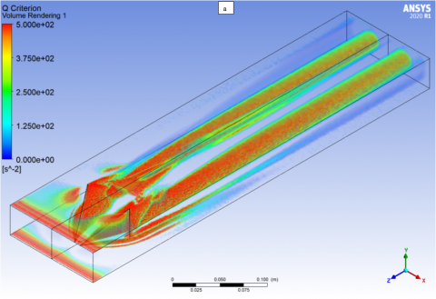
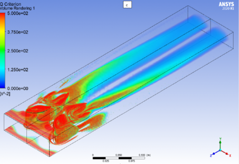
To investigate in more details the longitudinal vortices generated for the delta wing compared with the delta winglet and the curved rectangular winglet, the Q criterion was used. The Q criterion is defined in the Eq. (13):
$Q=\frac{1}{2}\left(u_{i, i}^{2}-u_{i, j} u_{j, i}\right)$ (13)
where, u is the velocity component, in the regions where the Q is greater than 1, the flow is dominated by the longitudinal vortices. We use the Q criterion, because this criterion can capture the main vortex structures in the flow field [14], also the longitudinal vortex intensity can be compared using the same scale.
Figure 8. Q criterion for the a) DWP, b) DW with β=30°, c) RWPC, by Reynolds number Re=4600
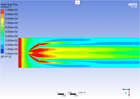
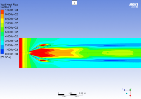
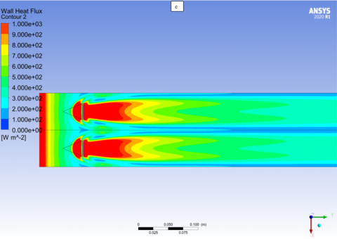
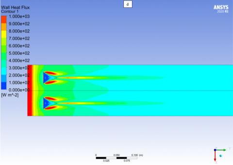
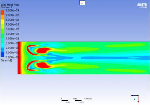
Figure 9. Wall heat flux [W/m2] for a) DWP, b) DWPI, c) DW with β=30°, d) DW with β=150°, e) RWPC, by Reynolds number Re=4600
Figure 10. Outflow temperature, [K]
The region after the delta winglet is dominated by a longitudinal vortex, that remains stable until channel exit, see Figure 8a, secondary vortices in the winglet can also observed. The delta wing with β=30° generates two vortices that also remain stable until channel exit, see Figure 8b, the distance between the vortices depends on delta wing width, secondary vortices are clearly seen in the wing region. In the curved rectangular winglet can be observed that important structures are generated around the winglet, but after the geometry the generated longitudinal vortices are weaker compared with the vortices generated by DWP or DW, because the Q value are near to cero at the channel exit, see Figure 8c.
The effects of longitudinal vortices on local heat transfer on the wall are showed in Figure 9. The wall heat flux variation are related with the interruption of the turbulent boundary layer, and the vortices generated by each geometry. Local heat flux near 1000 [W/m2] are found at the channel inlet and around the LVG due turbulent boundary layer separation around the generators, downstream the generators the effect of longitudinal vortices are clearly present. The DWP and the DMWI have similar characteristic, see Figure 9a and 9b. The effect of the attack angle on local heat transfer on delta wing is relevant. Using β=30o the area with high heat transfer are important, the DW with β=150° is not a good choice, see Figure 9c and 9d. Large area with low heat flux are found using RWPC, also this geometry is not suitable for high heat transfer enhancement, see Figure 9e.
To determinate the heat transfer rate, the outflow air temperature is necessary. Figure 10 shows the outflow temperature for the six cases. Using the curved rectangular winglet the air temperature increases in 10 K by Re=8000. Similar temperature increase are found for the delta winglet and for the inclined delta winglet. Delta wing reaches nearly the same outflow temperature as the delta winglet using β=30°. The delta wing with β=150° and the rectangular channel produce low heat transfer rate.
The average Nusselt number is plotted in Figure 11 As expected the Nusselt value increases with the Reynolds due to higher velocities, stronger vortices and better flow mix for all cases. Larger Nusselt number differences can be observed by high Reynolds number, where the flow is fully turbulent. The rectangular winglet pair curved produces the higher Nusselt number. Using delta winglet, the friction factor are similar between the inclined or not inclined delta winglet pair. The delta wing produce near the same Nusselt number than the delta winglet pair using β=30°.
Figure 11. Average Nusselt number
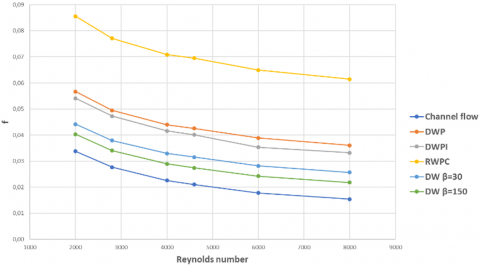
The friction factor is presented in Figure 12. As expected, the rectangular plane channel shows the lower friction coefficient. The delta wing with different angles present similar friction factor, with higher friction factor by using β=30°. The same tendency can be found by the delta winglet, the friction factor are similar between the inclined or not inclined delta winglet. The higher friction factor was found by the curved rectangular winglet pair, this could be associated by the structures formed around the winglet and weak vortices showed in Figure 8c.
Figure 12. Friction factor
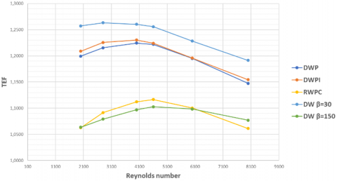
The thermal performance (TEF) factor compares the five investigated LVG geometries with the rectangular plane channel without LVG, considering the effects of heat transfer and the associated friction factor, is showed in Figure 13 and in Table 3. The best performance for every Reynolds studied is achieved by the DW with and attack angle of β=30°. The results obtained for the TEF shows that all the LVG geometries have a higher efficiency as plane channel, because the TEF is greater than one. The curves showed a maximum around a Reynolds number of 4000. The DW with and attack angle of β=30° shows a maximum TEF of 1.26 by Reynolds number of 2800, and decreases by Reynolds number greater than 4600. The TEF of DW is greater than the DWP, the lower performance was obtained by the RWPC and by the DW with and attack angle of β=150°.
The delta wing geometry with β=30° produces two stable longitudinal vortices with low pressure drop in a turbulent flow, this is also relevant in the wing design related to the drag and lift coefficients. The DW is a simple to manufacture geometry, and the TEF is only a little lower compared to other new, more complex to manufacture, conic type LVG recently reported in the literature [12, 13].
Figure 13. TEF for different LVG
Table 3. TEF for the different LVG geometries
|
Re |
DWP |
DWPI |
RWPC |
DW β=30 |
DW β=150 |
|
2000 |
1,199 |
1,209 |
1,063 |
1,257 |
1,064 |
|
2800 |
1,216 |
1,226 |
1,092 |
1,263 |
1,079 |
|
4000 |
1,224 |
1,230 |
1,112 |
1,260 |
1,097 |
|
4600 |
1,222 |
1,224 |
1,117 |
1,256 |
1,103 |
|
6000 |
1,195 |
1,196 |
1,100 |
1,228 |
1,098 |
|
8000 |
1,147 |
1,154 |
1,061 |
1,191 |
1,077 |
The purpose of this study was to compare the thermal performance between delta wing using two attack angles, delta winglet pair, inclined delta winglet pair and rectangular winglet pair curved by turbulent flow in a rectangular channel, using one LVG as basic unit in the channel.
A TEF of 1.26 by Reynolds number of 2800 was obtained with the delta wing with an attack angle of 30°, a smaller TEF was obtained the delta winglet pair and the inclined delta winglet pair, and using the rectangular winglet pair curved and the delta wing with an attack angle of 150° the lower TEF was obtained.
The TFE depends on LVG geometry and the Reynolds number, the effectivity of the LGV decrease with the Reynolds number. The delta wing is simple to manufacture and it is competitive, when the comparison unit is one LVG.
|
A |
surface area, m2 |
|
DH |
hydraulic diameter, m |
|
cp |
specific heat, J. kg-1. K-1 |
|
f |
friction factor |
|
h |
heat transfer coefficient, W.m-2.K-1 |
|
H |
channel height, m |
|
k |
turbulent kinetic energy, m2s-2 |
|
L |
channel length, m |
|
$\dot{m}$ |
mass flow, kg. s-1 |
|
Nu |
Nusselt number |
|
P |
pressure, Pa |
|
$\dot{q}$ |
heat flux, W.m-2 |
|
$\dot{Q}$ |
total heat transfer rate, W |
|
Re |
Reynolds number |
|
t |
time, s |
|
T |
temperature, K |
|
TEF |
thermal performance |
|
u |
velocity, m.s-1 |
|
v |
velocity, m.s-1 |
|
w |
velocity, m.s-1 |
|
x |
coordinate, m |
|
y |
coordinate, m |
|
z |
coordinate, m |
|
W |
channel width, m |
|
Greek symbols |
|
|
ρ |
density, kg.m-3 |
|
$\mu$ |
dynamic viscosity, N.s.m-2 |
|
ω |
specific dissipation, m2.s-2 |
[1] Thulukkanam. K. (2013). Heat Exchanger Design Handbook, second edition. CRC Press. https://doi.org/10.1201/b14877
[2] Biswas, G., Torii, K., Fujii, D., Nishino, K. (1996). Numerical and experimental determination of flow structure and heat transfer effects of longitudinal vortices in a channel flow. International Journal of Heat and Mass Transfer, 39(16): 3441-3451. https://doi.org/10.1016/0017-9310(95)00398-3
[3] Gentry, M.C., Jacobi, A.M. (2002). Heat transfer enhancement by delta-wing generated tip vortices in flat-plate and developing channel flows. Journal of Heat Transfer, 124(6): 1158-1168. https://doi.org/10.1115/1.1513578
[4] Tiggelbeck, S., Mitra, N.K., Fiebig, M. (1994). Comparison of wing-type vortex generators for heat transfer enhancement in channel flows. J. Heat Transfer, 116(4): 880-885. https://doi.org/10.1115/1.2911462
[5] Zhu, J.X., Mitra, N.K., Fiebig, M. (1993). Effects of longitudinal vortex generators on heat transfer and flow loss in turbulent cannel flows. International Journal of Heat and Mass Transfer, 36(9): 2339-2347. https://doi.org/10.1016/S0017-9310(05)80118-8
[6] Garelli, L., Rodriguez, G., Durella, J., Storti, M. (2019). Heat transfer enhancement in panel type radiators using delta-wing vortex generators. International Journal of Thermal Sciences, 137: 64-74. https://doi.org/10.1016/j.ijthermalsci.2018.10.037
[7] Oneissi, M., Habchi, C., Russeil, S., Bougeard, D., Lemenand, T. (2016). Novel design of delta winglet pair vortex generator for heat transfer enhancement. International Journal of Thermal Sciences, 109: 1-9. https://doi.org/10.1016/j.ijthermalsci.2016.05.025
[8] Song, K., Tagawa, T., Chen, Z., Zhang, Q. (2019). Heat transfer characteristics of concave and convex curved vortex generators in the channel of plate heat exchanger under laminar flow. International Journal of Thermal Sciences, 137: 215-228. https://doi.org/10.1016/j.ijthermalsci.2018.11.002
[9] Lu, G.F., Zhou, G.B. (2016). Numerical simulation on performances of plane and curved winglet type vortex generator pairs with punched holes. International Journal of Heat and Mass Transfer, 102: 679-690. https://doi.org/10.1016/j.ijheatmasstransfer.2016.06.063
[10] Liu, H., Fan, C., Nobes, D. (2019). Heat transfer and flow characteristics in a rectangular channel with combined delta winglet inserts. International Journal of Heat and Mass Transfer, 134: 149-165. https://doi.org/10.1016/j.ijheatmasstransfer.2019.01.004
[11] Min, C.H., Qi, C.Y., Wang, E.Y., Tian, L.T., Qin, Y.J. (2012). Numerical investigation of turbulent flow and heat transfer in a channel with novel longitudinal vortex generators. International Journal of Heat and Mass Transfer, 55: 7268-7277. https://doi.org/10.1016/j.ijheatmasstransfer.2012.07.055
[12] Dogan, M., Abir, A. (2021). An experimental comparison of delta winglet and novel type vortex generators for heat transfer enhancement in a rectangular channel and flow visualization with stereoscopic PIV. International Journal of Heat and Mass Transfer, 164: 120592. https://doi.org/10.1016/j.ijheatmasstransfer.2020.120592
[13] Zahit, H., Dogan, M., Abir, A. (2021). The numerical analysis of novel type conic vortex generator and comparison with known VGs for heat transfer enhancement. Heat and Mass Transfer, 58: 735-762. https://doi.org/10.1007/s00231-021-03117-7
[14] ANSYS Documentation, 2020. https://www.ansys.com/products/fluids/ansys-fluent.
[15] Oneissi, M., Habchi, C., Russeil, S., Lemenand, T., Bougeard, D. (2018). Heat transfer enhancement of inclined projected winglet pair vortex generators with protrusions. International Journal of Thermal Sciences, 134: 541-551. https://doi.org/10.1016/j.ijthermalsci.2018.08.032