Min Niu
© 2022 IIETA. This article is published by IIETA and is licensed under the CC BY 4.0 license (http://creativecommons.org/licenses/by/4.0/).
OPEN ACCESS
To figure out the wear process of ZrN-coated cutting tools under the thermal effect, this study performed wear experiments on ZrN-coated cutting tools during the machining process and tested on their hardness, elastic modulus, and microstructures under the thermal effect; then, the paper analyzed the internal laws and mechanisms of factors that cause wear to the ZrN-coated cutting tools under high temperature conditions, and determined their damaged state under certain load and speed conditions. After that, this paper summarized that the wear of ZrN-coated cutting tools during use can be divided into three stages: the running-in stage, the normal wear stage, and the acute wear stage. Through experiments, it’s found that the friction coefficient and wear rate of uncoated cutting tools were significantly higher than those of coated cutting tools; with the increase of load and rotate speed, the friction coefficient showed a decline trend; as the load increased, the wear rate showed an increase trend; as the rotate speed grew, the wear rate decreased; under the condition of a same kind of substrate, the friction reduction and anti-wear effect of cutting tools with a transition layer was better than those of cutting tools without a transition layer.
coated cutting tools, thermal effect, wear mechanism, wear stage
Coating is a good way to enhance the performance of cutting tools, and the invention of coated cutting tools has greatly improved the cutting properties of conventional cutting tools [1-5]. The coating of cutting tools is to apply one or more layers of hard-wearing refractory compound on the tool body with good toughness to combine the tool substrate with the hard coating, thereby greatly improving the performance of the cutting tools. Coated cutting tools can improve machining efficiency and accuracy, extend the service life of the tools, and reduce machining costs. Due to these merits, they have been developed very fast in recent years, and therewith the coating technique becomes more mature [6-9]. In western countries with developed industry, the proportion of coated blades in indexable blades is increasing year by year. In Sweden company Sandvik Group and the American company Kennametal Inc., this proportion has reached more than 85%. In the United States, the proportion of coated carbide blades used on CNC (Computer Numerical Control) machine tools is 80%. In Sweden and Germany, the proportion of coated blades used for turning has accounted for over 70%, and it’s expected that the proportion of coated cutting tools may exceed 80%.
Foreign studies have achieved some results in the research of wear resistance of coatings [10-14]. For example, the microhardness of the coatings could reach as high as about 400MPa, the adhesion force is excellent, and the critical load in scratch test could reach 80N. The wear resistance test shows that the service life of the drill bit coated with TiN and ZrN is respectively 5 times and 7 times higher than that of ordinary drill bits when they are applied to alloy steel plates. Moreover, research results also indicate that the coatings not only have good resistance to high-concentration strong acid, but also have excellent anti-wear and friction reduction properties. Also, the corrosion test proved that the corrosion resistance of ZrN is better than that of TiN.
The wear of the coated cutting tools is caused by the relative movement between the cutting tools and the surface of the object to be processed, high heat will be generated during this machining process, and the coating will be worn away continuously. The mechanical contact between the cutting tools and the surface of the object to be processed will cause friction, which will then generate thermal effect, under the action of multiple factors, the coating that wraps on the surface of the cutting tools will be scuffed or become brittle, thereby causing relative loss of the coating. Foreign scholars have carried out a lot of research on coated cutting tools [15-21] and found that the reasons of the thermal effect caused by different materials during the sliding process are quite complex, and both the materials and the working conditions are the factors affecting the performance of the coated cutting tools. Since the coating is attached to the body of the cutting tool, in fact, it is different from the simple friction between two objects, and it’s necessary to further analyze the anti-wear performance of the coating with the thermal effect taken into consideration.
The friction and wear characteristics of the coating materials of the cutting tools are not the inherent properties of the materials, they can be divided into the internal causes and external causes. Internal causes are factors other than the friction properties of the materials, such as temperature, speed, load, and friction methods, etc. The internal causes are mainly the physical and mechanical properties of the coating materials and their microstructures. This chapter aims to study the theories of the impact of the mechanical properties (such as hardness and elastic modulus) and microstructures of the coating materials on the performance of the cutting tools, in the hopes of providing theoretical evidences for subsequent experiments
2.1 Theoretical formulas of wear loss
Hardness and elastic modulus of the coating material are important internal factors of friction and wear. The calculation of the wear loss of the coating material is based on the theoretical formula (1) of performance and wear loss derived by Evans and Marshall [5]:
$V=\alpha \frac{P^{\frac{9}{8}}}{K_{I C}{ }^{\frac{1}{2}} H^{\frac{5}{8}}}\left(\frac{E}{H}\right)^{\frac{4}{5}} L$ (1)
where, V represents the wear volume; P represents the load; KIC represents the fracture toughness; H represents the hardness; E represents the elastic modulus; L represents the sliding distance; α represents a constant irrelevant to the material.
The wear rate W can be calculated according to Formula (2):
$W=\frac{V}{P L}=\alpha \frac{P^{\frac{1}{8}}}{K_{I C}^{\frac{1}{2}} H^{\frac{5}{8}}}\left(\frac{E}{H}\right)^{\frac{4}{5}}$ (2)
According to Formula (2), the wear rate W is inversely proportional to the hardness of the coating.
2.2 Wear resistance of the coating of cutting tools
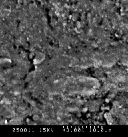
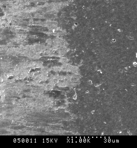
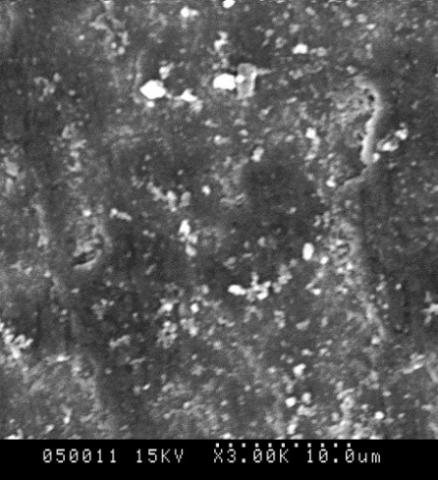
Figure 1. An SEM photo of the surface of the coated cutting tool under the thermal effect
During the machining process of cutting tools, there’s friction between the cutting tool and the object to be processed, and the frictional stress and thermal stress are likely to occur at the positions of voids and tiny cracks. The existence of pores can cause severe wear. If the pores are small and evenly distributed, they can form cavities that can store the lubricants, thereby improving the wear resistance of the coating layer. A SEM photo was taken in the experiment, as shown in Figure 1, the coating was dense and uniformly distributed. To improve the overall performance of the coated cutting tool and eliminate the problem of stress concentration, when preparing the coated cutting tools, pores should be avoided as much as possible so as not to cause uncertainties in subsequent experiment.
3.1 Wear test conditions
In this research, three factors load, rotate speed, and friction distance were tested under the thermal stress generated during the machining of ZrN-coated cutting tools. The coating layers of cutting tool samples G2 and G3 were taken as the research objects, and their parameters are listed in Table 1 below. A high-speed ring/block-type wear testing machine was used in the experiment, all tests were performed at room temperature. The test blocks were made of ZrN-coated cutting tools; the size was 13mm*10mm*4.8mm (length*width*height). The test rings were made of HRC 45# quenched steel, the outer diameter was 50mm, the inner diameter was 35mm, and the width was 13mm. The working condition was dry friction. During the experiment, the test block was fixed by a clamper, and the test ring rotated at a speed of 100-500r/min. The load was applied to the friction surface in the normal direction, and changed between 10-70. Before the experiment, the test pieces were ultrasonically cleaned twice in acetone and dried before use. After rubbing for 3 min, the friction force was recorded and the average friction coefficient was calculated; then the wear loss of the ZrN-coated cutting tools was calculated by the volume method, and finally the wear rate was calculated as well. When measuring the wear volume, each time the friction lasted for 3min, and the average value of 12 measured data was taken as the result. Then the wear characteristics of the coated cutting tools were determined according to the wear morphology and wear mechanism under conditions of different factors.
3.2 Morphology comparison of coating layers of G2 and G3 under different parameters
Figures 2(a) and (b) are SEM photos of the worn surface morphology of sample G2 under the thermal effect after subjected to friction at a rotate speed of 300 r/min and under a load of 10 N and 70 N, respectively. According to Figure 2(a), when the load was 10N, there’re shallow furrow-like wear marks on the coating surface, which was caused by repeated cutting and plastic deformation of the protrusions on the coating surface under the friction and extrusion actions of the grinding ring. The protruded particles on the surface were relatively large and gradually ground to become flatter, then with the increase of the friction time, the brittleness of the wear area on the surface increased; moreover, during the wear process, due to the existence of large tensile stress, cracks generated and expanded, causing the binding with the coating layer to become unstable, some particles peeled off from the coating layer easily, and they might become new abrasive particles. Generally, it’s believed that the wear of these abrasive particles is that the particles contact the material surface at a certain angle under the action of external force, and the force acted on the particles can be decomposed into a component force perpendicular to the material surface and a component force parallel to the material surface. The perpendicular component force makes the abrasive particles press into the material surface, and the parallel component force makes the abrasive particles that have been pressed into the material surface move tangentially, generating scratches or micro cuttings on the material surface, and leaving wear marks on it, namely the furrow-like wear marks, thereby forming grinding and cutting actions on the material surface.
Table 1. Experimental parameters of coated cutting tools
|
Serial number of sample |
Substrate |
Coating layer |
Hardness (GPa) |
Binding force (N) |
Thickness of the coating layer (μm) |
Processing parameters |
|||
|
N2 flow (SCCM) |
Temperature (℃) |
Current (A) |
Voltage (V) |
||||||
|
G2 |
YG6 |
ZrN |
23.62 |
63.00 |
3.75 |
40 |
250 |
85 |
200 |
|
G3 |
YG6 |
ZrN |
16.97 |
61.50 |
3.84 |
100 |
200 |
90 |
200 |
(a) The coating layer of G2 under 10N load
(b) The coating layer of G2 under 70N load
Figure 2. SEM photos of wear morphology of G2 under 10N and 70N loads
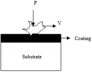
Figure 3. Contact state of abrasive particles and the coating layer
Figure 4. Schematic diagram of micro-cracking during wear
In the friction process, due to the existence of thermal stress, furrows are formed on the coating layer due to the cutting of the protrusions of the grinding test pieces and the external hard abrasive particles, and the raised parts of the furrows are subjected to abrasion and rolling, after reaching the limit of plastic deformation, they would break and fall off to become hard abrasive particles, and the contact state of the abrasive particles and the coating layer is shown as Figure 3. Also, Figure 4 gives a diagram showing the formation of the cracks. When the load was 10N, the wear mechanism of the coating of sample G2 was the wear of abrasive particles characterized by micro cuttings.
As shown in Figure 2(b), when the load was increased to 70N, under the thermal effect caused by friction, the scratches became deeper, and the peeling area on the coating layer increased, peeling pits were observed obviously, the wear volume increased, and the material surface was very rough, resulting in a sharp increase in the wear rate. This is because the higher the hardness of the coating, the lower the fatigue strength, since harder materials often bear greater loads than soft materials, they are more prone to fatigue. In addition, since the physical parameters of the coating and the substrate are different, when they are subjected to force and undergo plastic deformation, inevitably their deformations are asynchronous, which would result in cracks on the phase interface, then the phase boundary would hinder the movement of dislocations, and such dislocations would pile up at the phase boundary, causing stress concentration and crack growth. These phenomena were completely consistent with the change trend of the coating wear volume-load curve. When the load was 70N, the wear mechanism of the coating of sample G2 was local fatigue peeling.
When the friction just started, there’s only slight wear of the abrasive particles; then as the friction continues, the coating began to fatigue, producing local fatigue peeling.
(a) 100 r/min
(b) 500 r/min
Figure 5. SEM photos of wear topography of the coating layer of sample G2 at rotate speeds of 300 r/min and 500 r/min
Figures 5(a) and 5(b) are SEM photos of the worn surface morphology of the coating layer of sample G2 under the thermal effect of friction at a load of 70 N and rotate speeds of 100 r/min and 500 r/min, respectively. Figure 5(a) shows that, at a low rotate speed of 100 r/min, the friction surface of the coating was very rough, there’re deep groove-like wear marks and pits remaining after a large number of hard particles peeled off. Figure 5(b) shows that, at a high rotate speed of 500 r/min, the friction surface of the coating layer was relatively smooth, the wear marks were shallow furrows, and there’re fewer peeling pits, indicating that under high speed, the friction reduction and anti-wear effect was better.
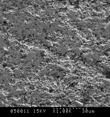
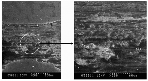
Figure 6(a) and 6(b) are SEM photos of the worn surface morphology of the coating layer of samples G2 and G3 under the thermal effect generated at a load of 70 N and a rotate speed of 300 r/min.
Figure 6(a) shows that there’re deep cracks on the worn surface of the coating layer of sample G2; while Figure 6(b) shows that the coating layer of G3 only had bits of local peelings. This is because for the coating layer of sample G2 which didn’t have a Zr transition layer, it was subjected to load and there’re hard protrusions pressed into it, cracks were easily formed due to the plastic deformation of the substrate; after cracks generated and spread to the interface of the substrate, the distance was very short, and the wear rate of the coating was high. As for the coating layer of sample G3 which had a Zr transition layer, the expansion of cracks was limited, the cracks initiated from the top ZrN layer and grew to interface of the transition layer, since the bonding strength was stronger than the bonding strength of ZrN and the substrate, so it’s not easy to crack; the cracks changed the direction and continued to expand to the transition layer, since the Zr transition layer had a certain toughness, it can delay the expansion of the cracks, then the cracks continued to expand to the interface between the transition layer and the substrate, which was equivalent to lengthening the path of crack expansion, thereby enhancing the damage resistance of the coating layer. Therefore, the number of cracks on the coating was less, there’re only slight peelings on the coating, and the wear rate of the coating layer was low. The crack expansion of the transition layer is shown in Figure 7.
(a) The coating layer of sample G2
(b) The coating layer of sample G3
Figure 6. Wear morphology of samples G2 and G3 under conditions of a load of 70 N and a rotate speed of 300 r/min
Figure 7. Crack expansion of the coating layers of samples G2 and G3
|
(a) 50 m |
(b) 1000 m |
|
(c) 1250 m |
|
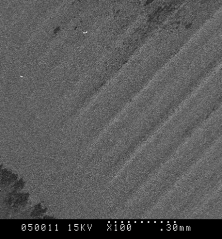
Figure 8. Wear topography of the coating layer of sample G2 under conditions of 40 N load and 300 r/min rotate speed
Figures 8(a) and 8(b) are SEM photos of the wear morphology of the coating layer surface of sample G2 under the conditions of 40 N load and 300 r/min rotate speed. According to Figures 4-8, in the wear test of the dry friction of sample G2, the wear rate of the coating layer showed three wear stages with the change of friction distance, namely the running-in stage, the normal wear stage, and the acute wear stage.
As can be seen from Figure 8(a), after the coating layer of sample G2 was subject to running-in for about 50 m, the micro protruded peaks on the surface exhibited brittle fracture, peeling pits or peeling belts were formed, since the micro protruded peaks had been worn away already, the surface of the coating became smoother.
Figure 8(b) shows that, after the running-in stage was over, the coating layer of sample G2 entered the normal wear stage. After subjected to running-in wear, the micro protruded peaks on the surface were worn away, the surface become smoother, the contact area increased, the contact stress decreased and gradually tended to be stable; after running-in, although surface grain particles had severe defects, the preferred orientation of the grain surface was changed, which had strengthened the orientations, and exerted an inhibitory effect on the expansion rate of the cracks, thereby alleviating the peeling off and wear of the coating layer and improving its wear resistance.
Figure 8(c) shows large flakes peeling off from the surface of the coating layer of sample G2, which means that it entered the acute wear stage, and the trace of plastic sliding had no longer existed on the surface of the coating layer of sample G2. At this time, before peeling off and brittle fracture, the residual ZrN coating left on the worn surface didn’t have to go through the plastic deformation stage, the density of cracks at the surface and cross-section was extremely high, the expansion speed of cracks was accelerated, and the surface ZrN coating was cracked severely.
Through experiments, this study determined the internal and external factors affecting the wear process of the ZrN-coated cutting tools under the thermal effect, that is, the external factors are mainly load, rotate speed, and friction distance; and the internal factors are mainly the mechanical properties and microstructures of the coating layer. By analyzing the SEM photos of the worn surface under different loads, it’s concluded that under a small load, the friction surface of the coating layer was relatively flat, there’re shallow furrow-like wear marks, and the pits formed by the falling off of hard particles were small; while under a large load, the friction surface of the coating layer was rougher, the wear marks were wide and deep furrows, the pits formed by the falling off of hard particles were large, the coating peeled off in large flakes, indicating that the coating layer had suffered severe wear.
By analyzing the SEM photos of the worn surface at different rotate speeds, it’s concluded that at a low speed, the friction surface of the coating layer was very rough, there’re deep groove-shaped wear marks and pits formed after a large number of hard particles had fallen off; while at a high speed, the friction surface of the coating layer was smoother, the wear marks were shallow furrows, the pits formed were less, and the area formed by the peeling off of coating in flakes was smaller, indicating that at high-speed, the friction reduction and anti-wear effect of sample G2 was better. The wear rate of ZrN-coated cutting tools varied with the increase of the friction distance, and it exhibited three wear stages: the running-in stage, the normal wear stage, and the acute wear stage. During the machining process, the coating layer of sample G2 showed two wear forms, the abrasive particle wear and the fatigue wear; while the coating layer of sample G3 showed only one wear form, the abrasive particle wear.
[1] Gao, H.N., Shen, H.D., Yu, L., Wang, Y.L., Yang, Y., Yan, S.C., Hu, Y.J. (2021). Frictional wear detection of hard alloy tool material during high-speed cutting. International Journal of Heat and Technology, 39(6): 1845-1852. https://doi.org/10.18280/ijht.390619
[2] Margabandu, V., Radhakrishnan, R. (2021). Multi objective study on machining characteristics of AISI H-11 tool steel prepared by different processing techniques. Journal Européen des Systèmes Automatisés, 54(2): 243-251. https://doi.org/10.18280/jesa.540206
[3] Strano, M., Albertelli, P., Chiappini, E., Tirelli, S. (2015). Wear behaviour of PVD coated and cryogenically treated tools for Ti-6Al-4V turning. International Journal of Material Forming, 8(4): 601-611. https://doi.org/10.1007/s12289-014-1215-6
[4] Chang, K.S., Zheng, G.M., Li, Y.Y., Cheng, Y.X., Liu. H.B., Zhao, G.X. (2021). Effect of wet micro-blasting on surface integrity and cutting performance of coating tools for TC4 cutting. Materials Reports, 35(16): 16086-16092. https://doi.org/10.11896/cldb.20070196
[5] Sui, S.C., Feng, P.F. (2016). The influences of tool wear on Ti6Al4V cutting temperature and burn defect. The International Journal of Advanced Manufacturing Technology, 85(9): 2831-2838. https://doi.org/10.1007/s00170-015-8093-z
[6] Jacob, A., Gangopadhyay, S., Satapathy, A., Mantry, S., Jha, B.B. (2017). Influences of micro-blasting as surface treatment technique on properties and performance of AlTiN coated tools. Journal of Manufacturing Processes, 29: 407-418. https://doi.org/10.1016/j.jmapro.2017.08.013
[7] Nouari, M., Ginting, A. (2006). Wear characteristics and performance of multi-layer CVD-coated alloyed carbide tool in dry end milling of titanium alloy. Surface and Coatings Technology, 200(18-19): 5663-5676. https://doi.org/10.1016/j.surfcoat.2005.07.063
[8] Shi, Q., Li, L., He, N., Zhao, W., Liu, X. (2013). Experimental study in high speed milling of titanium alloy TC21. The International Journal of Advanced Manufacturing Technology, 64(1): 49-54. https://doi.org/10.1007/s00170-012-3997-3
[9] Ulutan, D., Ozel, T. (2011). Machining induced surface integrity in titanium and nickel alloys: A review. International Journal of Machine Tools and Manufacture, 51(3): 250-280. https://doi.org/10.1016/j.ijmachtools.2010.11.003
[10] Hisakado, T., Akiyama, K. (1999). Mechanisms of friction and wear of metals against ceramics in vacuum. Wear, 224(2): 274-281. https://doi.org/10.1016/S0043-1648(98)00418-9
[11] Wu, D., Zhang, Z., Fu, D., Fan, W., Guo, H. (1997). Structure, electrical and chemical properties of zirconium nitride films deposited by dc reactive magnetron sputtering. Applied Physics A: Materials Science & Processing, 64(6): 593-595. https://doi.org/10.1007/s003390050522
[12] Sue, J.A., Chang, T.P. (1995). Friction and wear behavior of titanium nitride, zirconium nitride and chromium nitride coatings at elevated temperatures. Surface and Coatings Technology, 76: 61-69. https://doi.org/10.1016/0257-8972(95)02506-5
[13] Gruss, K.A., Zheleva, T., Davis, R.F., Watkins, T.R. (1998). Characterization of zirconium nitride coatings deposited by cathodic arc sputtering. Surface and Coatings Technology, 107(2-3): 115-124. https://doi.org/10.1016/S0257-8972(98)00584-2
[14] Larijani, M.M., Tabrizi, N., Norouzian, S., Jafari, A., Lahouti, S., Hosseini, H.H., Afshari, N. (2006). Structural and mechanical properties of ZrN films prepared by ion beam sputtering with varying N2/Ar ratio and substrate temperature. Vacuum, 81(4): 550-555. https://doi.org/10.1016/j.vacuum.2006.07.018
[15] Le, V.V., Nguyen, T.T., Kim, S.K. (2013). The influence of nitrogen pressure and substrate temperature on the structure and mechanical properties of CrAlBN thin films. Thin Solid Films, 548: 377-384. https://doi.org/10.1016/j.tsf.2013.09.041
[16] Yao, Y., Li, J., Wang, Y., Ye, Y., Zhu, L. (2015). Influence of the negative bias in ion plating on the microstructural and tribological performances of Ti–Si–N coatings in seawater. Surface and Coatings Technology, 280: 154-162. https://doi.org/10.1016/j.surfcoat.2015.09.005
[17] Yoon, S.Y., Yoon, S.Y., Chung, W.S., Kim, K.H. (2004). Impact-wear behaviors of TiN and Ti–Al–N coatings on AISI D2 steel and WC–Co substrates. Surface and Coatings Technology, 177: 645-650. https://doi.org/10.1016/j.surfcoat.2003.08.067
[18] Gurrappa, I. (2003). Characterization of titanium alloy Ti-6Al-4V for chemical, marine and industrial applications. Materials Characterization, 51(2-3): 131-139. https://doi.org/10.1016/j.matchar.2003.10.006
[19] Ferriere, A., Lestrade, L. (2002). Solar processing for the glazing of ZrO2-Y2O3 thermal barrier coatings: reduction of crack initiation. Journal of Solar Energy Engineering, 124(3): 315-317. https://doi.org/10.1115/1.1488163
[20] Hariharan, M.K., Rajkamal, M.D., Ravikumar, K., Mohammed, M.S. (2021). Investigation on effect of TiN, TiAlN & DLC-triple layer coated carbide tool in machining of Al-Si 4032 alloy. Materials Today, In Press. https://doi.org/10.1016/j.matpr.2021.10.197
[21] Çalışkan, H., Küçükköse, M. (2015). The effect of aCN/TiAlN coating on tool wear, cutting force, surface finish and chip morphology in face milling of Ti6Al4V superalloy. International Journal of Refractory Metals and Hard Materials, 50: 304-312. https://doi.org/10.1016/j.ijrmhm.2015.02.012