Yingjie Zhu | Xiangfeng Li* | Ming Zhang | Zhiyan Zhang | Zuling Ren
© 2022 IIETA. This article is published by IIETA and is licensed under the CC BY 4.0 license (http://creativecommons.org/licenses/by/4.0/).
OPEN ACCESS
Permanent magnet synchronous generator (PMSG) is widely used in wind power generation systems. However, the temperature of the PMSG may change due to the demagnetization fault of permanent magnets. This paper discusses the loss of heat source distribution for the PMSG, analyzes the thermal conductivity of relevant materials, and determines the boundary conditions for modeling. Then, a three-dimensional (3D) temperature field calculation model was established for the PMSG under demagnetization fault, according to thermal principles and fluid theorems. With the aid of the model, the authors obtained the temperature variation of stator windings, stator cores, and permanent magnets with different demagnetization degrees in different locations. After that, an experimental platform was set up for the PMSG temperature variation under demagnetization fault, and a temperature rise experiment was conducted to verify the effectiveness of our temperature field calculation model and the correctness of the temperature field variation law.
permanent magnet synchronous generator (PMSG), demagnetization fault, three-dimensional (3D) temperature field, heat source, loss
The development of clean, renewable energy can alleviate energy shortages and environmental pollution. In 2018, renewable energy contributed 36.5% of the total electric power generated in China, and wind power ranked first in renewable energy power generation [1]. As the core equipment of wind power generation, the permanent magnet synchronous generator (PMSG) is excited by permanent magnets. But the permanent magnets of the rotor may suffer demagnetization fault, under various internal faults and abnormal operating conditions. When a permanent magnet is in a high temperature and overloaded working environment or due to age restrictions, it will cause irreversible partial demagnetization or uniform demagnetization of PM [2-4]. Such a fault would degrade the output performance of PMSG, the no-load back EMF of the motor will decrease, and the torque output capacity will be significantly reduced, which will seriously affect the performance of the motor. In order to maintain the same torque output capacity after a demagnetization failure, the input current of the motor will be greatly increased, lead to abnormal heating, and even cause generator breakdown [5-7]. Therefore, it is necessary to study the temperature field of the PMSG under demagnetization fault.
At present, there are many related works about the calculation method of motor temperature field in the related fields at home and abroad. For example, Wang et al. [8] analyzed the eddy current loss at the end of the generator by establishing a temperature field model of the hydro-generator, and obtained the distribution law of the electromagnetic-thermal coupling field. Shi et al. [9] established a three-dimensional temperature field model of the asynchronous motor by using heat transfer theory, analyzed the temperature field and fluid field of the generator, and obtained the maximum heat source and heat conduction direction in the generator. Liang et al. [10] adopted the finite element method (FEM) to integrate the fluid field with the temperature field for a turbo-generator, established the fluid-heat transfer coupling field, and derived the three-dimensional (3D) temperature distribution of the motor. Kang et al. [11] simulated and analyzed the electromagnetic field, fluid field and three-dimensional global steady-state temperature field of a 560 kVA PMSG, and obtained the distribution characteristics of the motor temperature field. Chowdhury et al. [12] established a lump-parameter equivalent thermal circuit model for a single induction motor, predicted the transient thermal characteristics and coil temperature rise characteristics of the motor, and optimized the motor thermal analysis method. Ma et al. [13] established a thermocouple and a three-dimensional model based on the thermoelectric coupling method, which simultaneously considered frictional heat generation, excitation current heat generation and system convection heat dissipation, and analyzed the three-dimensional temperature field distribution of the brush slip ring system. Song et al. [14] proposed an identification method that uses the partial demagnetization fault of the permanent magnet synchronous linear motor (PMSLM) as the fault characteristic signal. This method can accurately identify the demagnetization position and the degree of demagnetization. Zhang et al. [15] analyzed the loss and temperature distribution of a high-speed PMSM with an interior permanent magnet rotor. The field-circuit coupling simulation method is used to analyze the characteristics of PMSG loss distribution. Zhu et al. [16] established a high-precision finite-formula mathematical model of the convective heat transfer boundary based on the basic theory of the finite formula method and calculated the three-dimensional temperature field of the permanent magnet motor. Jan et al. [17] constructed an analytical model, set a sensing coil in each air gap, calculated the sensing coil back-EMF, and solved the electromagnetic inverse problem to find the demagnetization amount and location of the demagnetization defect. Yu et al. [18] based on the time-stepping finite element method coupling with the circuit, the electromagnetic field of a 400W PMSWG was simulated under the demagnetization fault. Analyzed the effect of Demagnetization fault on related parameters in Permanent magnet Wind Generator.
In this paper, a 1kW, 12-pole PMSG is taken as the research object, the variation law of the magnetic field affected by the temperature under the demagnetization fault is studied, and the coupling process of the electromagnetic field and the temperature field is analyzed. Considering the influence of winding resistivity changes under temperature field, the solution method of copper loss of motor under temperature field is optimized. The equivalent simplification method is adopted to simplify the internal structure of the motor, to determine the calculation method of heat loss and equivalent thermal conductivity of the generator. And establishes a numerical model for the temperature field of the generator under normal conditions and demagnetization fault, referring to the theory of heat transfer and finite volume method. On this basis, the authors analyzed the temperature variation law of the generator under the demagnetization fault. After that, an experimental platform was set up for the temperature change, and a temperature rise experiment was carried out. The experimental results show that the temperature field model of the demagnetization fault is valid, and the obtained relationship between temperature rise and demagnetization degree is correct. The theoretical analysis model established by this study has better analyzed the variation law of the temperature field under the demagnetization fault. The operating condition of the motor can be judged through the real-time monitoring of the motor temperature field, which sheds new light on the research and diagnosis of the demagnetization fault of the PMSG.
The temperature of the generator is mainly related to the internal losses and the thermal conductivity of the relevant materials. The PMSG has a fully enclosed surface for natural wind cooling. The heat of the generator is primarily dissipated in two ways: conveying the winding heat to the air via the stator and casing, and releasing the internal heat from the air gap to the rotor core.
2.1 Heat source distribution
The loss of the generator mainly includes the copper loss of stator windings, the stator core loss, the eddy current loss of the permanent magnets, and the mechanical loss. Among them, the mechanical loss is so small as to be negligible. By contrast, the copper loss accounts for a large portion of the total loss [19]:
${{P}_{cu}}=mI_{t}^{2}R$ (1)
where, Pcu is the copper loss of the stator windings; m is the phase number of the generator; Itis the phase current under different degrees of demagnetization fault; R is the actual resistance of the stator windings.
Once a demagnetization fault occurs, the generator may operate asymmetrically, producing an asymmetric current. In this case, since the winding of the PMSG is made of copper, The resistivity of copper is related to the temperature of the generator and the temperature coefficient of the material itself. The temperature coefficient of copper material will also change with the temperature of the PMSG. The temperature coefficient of copper ∂ at temperature θ is [20]:
$\partial =\frac{1}{234.5+\theta }$ (2)
where, ∂ is the temperature coefficient of copper, θ is the internal temperature of the motor.
The resistance of copper is:
${{R}_{\theta }}={{R}_{20}}\left[ 1+\partial \left( \theta -20 \right) \right]$ (3)
where, R20 is the resistance of copper at 20°C.
When demagnetization failure occurs, the internal temperature of the generator changes, the resistance value of the copper material also changes accordingly, which is not a constant resistance value in an ideal state. Therefore, it can be seen from formula (1) that the copper loss of winding is directly proportional to the actual resistance of stator winding, and the change of resistance value of winding resistance caused by temperature will lead to a certain error in the calculated copper loss of winding. To overcome the error, an experimental platform was built to test the input and output powers of the generators with a power analyzer, and an electromagnetic model was established to calculate the stator core loss and the eddy current loss of the permanent magnets. Then, the copper loss of the windings can be calculated by:
${{P}_{cu}}={{P}_{1}}-{{P}_{2}}-{{P}_{v}}-{{P}_{w}}$ (4)
where, P1 and P2 are the input power and output power of the generator respectively; Pv and Pw are the stator core loss and eddy current loss of permanent magnets respectively. Under different degrees of demagnetization fault, the Pv and Pw of permanent magnets can be solved by the electromagnetic field simulation model of the PMSG demagnetization fault. The stator core loss can be calculated by Dr. Bertotti’s iron loss separation model [21]:
$\begin{align} & {{P}_{v}}={{P}_{h}}+{{P}_{c}}+{{P}_{e}}={{K}_{h}}fB_{\max }^{2} \\ & +{{K}_{c}}fB_{\max }^{2}{{K}_{e}}fB_{\max }^{\frac{3}{2}} \\\end{align}$ (5)
where, Kh, Kc, and Ke are hysteresis, eddy current, and additional loss coefficient respectively; f is frequency; Bmaxis the magnetic density amplitude. According to the hysteresis loop of the silicon steel sheet, Kh=184.23367054, Kc=0.3862605926, and Ke=0.270231418.
Table 1 lists the experimental and finite-element simulation results on the copper loss, stator core loss, and eddy current loss of permanent magnets in the PMSG under normal conditions and different kinds of demagnetization fault. Note that the demagnetization location is illustrated in Figure 4.
Table 1. Loss of the PMSG under normal condition and demagnetization fault
|
Permanent magnet working condition |
Copper loss (W) |
Stator core loss (W) |
Eddy current loss (W) |
|
Normal conditions |
73.28 |
10.74 |
5.62 |
|
Single-block 50% demagnetization |
62.51 |
10.37 |
5.08 |
|
Single-block complete demagnetization |
59.65 |
9.91 |
4.41 |
|
Symmetric two-block 50% demagnetization |
64.37 |
9.85 |
4.35 |
Table 2. Thermal conductivity of the materials (W/(m2∙K))
|
Material |
Thermal conductivity |
Material |
Thermal conductivity |
|
Steel plate |
38 |
Silicon steel sheet |
40 |
|
Permanent magnets |
8.96 |
Slot insulation |
0.26 |
|
Winding |
401 |
Air gap |
0.0118 |
|
Rotor core |
12.1 |
Casing surface |
7.5 |
2.2 Thermal conductivity of materials
The generator has a complicated internal structure. The air gap between stator windings, stator, and rotor must be specialized to simplify the calculation and analysis. It is assumed that the stator slots are completely impregnated by insulating varnish, and uniformly filled with windings. Moreover, the insulation varnish of the windings is evenly distributed, and the slot insulation is closely combined with the stator slots and the copper wires, with a negligible temperature difference between the wires in the slot. On this basis, the various materials, such as the insulation varnish in the stator slots, were likened to windings with the same volume as the slot. Drawing on [8], the thermal conductivity of the windings can be calculated by:
${{\lambda }_{eq}}=\sum\nolimits_{i=1}^{n}{\frac{{{\delta }_{i}}}{(\sum\nolimits_{i=1}^{n}{\frac{{{\delta }_{i}}}{{{\lambda }_{i}}})}}}$ (6)
where, $\lambda_{e q}$ is the thermal conductivity of the windings, $\mathrm{W} /\left(\mathrm{m}^{2} \cdot \mathrm{K}\right) ; \delta_{\mathrm{i}}$ is the thickness of various equivalent materials, $\mathrm{m} ; \lambda_{i}$ is the thermal conductivity of each material, $\mathrm{W} /\left(\mathrm{m}^{2} \cdot \mathrm{K}\right)$.
The heat convection between the air gap, stator, and the rotor is realized as the air flows in the air gap under the driving effect of the rotation of the rotor. The equivalent thermal conductivity was introduced for the turbulence of the airflow in the air gap. The airflow in the air gap is comparable to a stationary fluid. Thus, the heat exchange capability of the airflow in the air gap was described with the thermal conductivity of the stationary fluid. The equivalent thermal conductivity of the air can be calculated by:
${{\lambda }_{eff}}=0.0019\cdot {{\eta }^{-2.9084}}\cdot {{\operatorname{Re}}^{0.4614\ln (3.33361\cdot \eta )}}$ (7)
where, $\eta=\frac{r_{0}}{r_{i}}, r_{0}(m)$ and $r_{0}(m)$ is the outer diameter and inner diameter of the stator, respectively; $R_{e}=\frac{n \phi_{1} \delta}{v}$ is the Reynolds number in the air gap. The value of $R_{e}$ was calculated as $25.10$.
The thermal conductivity of each part of the PMSG was derived by formulas (4) and (5). The results are recorded in Table 2.
3.1 Boundary conditions
According to the basic theory of heat transfer and fluid mechanics, the 3D steady-state temperature field model of the generator with surface natural wind cooling should satisfy the following boundary conditions:
$\left. \begin{matrix} T(x,y,z)|\Gamma ={{T}_{0}} \\ {{k}_{x}}\frac{\delta T}{\delta x}{{n}_{x}}+{{k}_{y}}\frac{\delta T}{\delta y}{{n}_{y}}+{{k}_{z}}\frac{\delta T}{\delta z}{{n}_{z}}=q \\ {{k}_{x}}\frac{\delta T}{\delta x}{{n}_{x}}+{{k}_{y}}\frac{\delta T}{\delta y}{{n}_{y}}+{{k}_{z}}\frac{\delta T}{\delta z}{{n}_{z}}=h({{T}_{f}}-{{T}_{b}}) \\\end{matrix} \right\}$ (8)
where, $\Gamma$ is the heat transfer boundary; $k_{x}, k_{y}$ and $k_{z}$ are the thermal conductivity coefficients in the $X, Y$, and $Z$ directions in rectangular coordinates, respectively; $n_{x}, n_{y}$, and $n_{z}$ are the normal vectors in the $X, Y$, and $Z$ directions, respectively; $q$ is the heat source density; $h$ is the heat convection coefficient; $T_{b}$ is the ambient temperature; $T_{f}$ is the adiabatic wall temperature of the boundary layer.
3.2 Model construction
For the given 1kW PMSG, the permanent magnets are surface mounted, and the heat is dissipated by surface natural wind cooling. Table 3 lists the rated parameters and basic dimensions.
Table 3. Basic parameters of the PMSG
|
Parameter |
Numerical value |
Parameter |
Numerical value |
|
Rated power/W |
1000 |
Rated voltage/V |
48 |
|
Rated speed/r/min |
500 |
Number of stator slots/ poles |
36/12 |
|
Core length/mm |
80.46 |
Stator outer diameter/mm |
161.6 |
|
Stator inner diameter/mm |
113 |
Permanent magnet thickness/mm |
24 |
|
Rotor outer diameter/mm |
109.88 |
Permanent magnet arc length/rad |
28 |
Based on SolidWorks, the 3D model of the generator was established with the geometric parameters. Under the assumptions of stator slot and air gap in Subsection 2.2, the equivalent windings, slot insulation, and airflow in the air gap were modeled, the designed motor model is double - layer winding, 12 poles, and 36 slots, in order to reduce the cogging torque when the generator starts, 3 empty slots are left, the rotor core is hollow design, which can greatly reduce the weight of the generator. The winding of the generator is made of copper, and the core of the stator and rotor are made of nonlinear ferromagnetic material, producing the 3D model of the PMSG (Figure 1).
Figure 1. 3D model of PMSG
The demagnetization fault disrupts the distribution of the magnetic field and the asymmetric operation of the PMSG, causing a change to the loss and its distribution in the generator. The generator loss directly affects the internal temperature distribution. This paper analyzes the temperature distribution and variation law of the generator under normal conditions, and three kinds of demagnetization fault: single-block 50% demagnetization, single-block complete demagnetization, and symmetric two-block 50% demagnetization.
4.1 Temperature distribution and variation law of windings and stator core
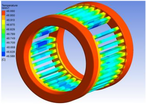
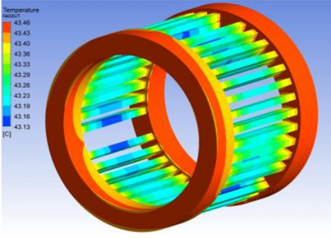
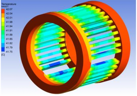
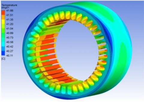
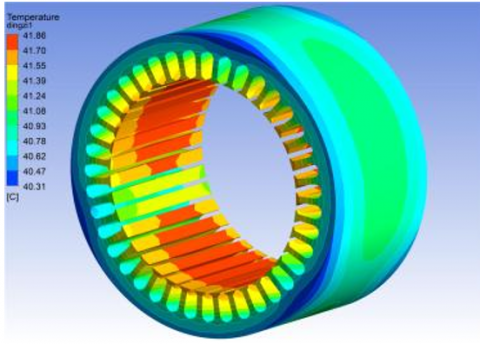
The copper loss of stator windings, accounting for the greatest part of the total loss, is the leading impactor of the temperature distribution of the generator. Figure 2 shows the temperature distribution of stator windings under normal conditions and different kinds of demagnetization fault. Under both natural conditions and demagnetization fault, the temperature peaked at the windings; the outer layer windings were slightly hotter than the inner layer windings; the lowest temperature appeared in the middle of the inner layer windings.
(a) Normal conditions
(b) Symmetric two-block 50% demagnetization
(c) Single-block 50% demagnetization
(d) Single-block complete demagnetization
Figure 2. Temperature distribution of stator windings under normal conditions and demagnetization fault
In the event of demagnetization fault, the temperature of the stator windings decreased across the board. Under single-block demagnetization, the temperature drop increased with the demagnetization degree. The temperature under symmetric two-block 50% demagnetization was 0.32% lower than that under single-block 50% demagnetization. This is because the asymmetric magnetic field distribution under single-block 50% demagnetization is more severe than that under symmetric two-block 50% demagnetization. The temperature of the windings is also affected by the stator core loss. The core loss under symmetric two-block 50% demagnetization was lower than that under single-block 50% demagnetization. That is why the winding temperature under symmetric two-block 50% demagnetization is much cooler than that under single-block 50% demagnetization.
4.2 Temperature distribution and variation law of stator core
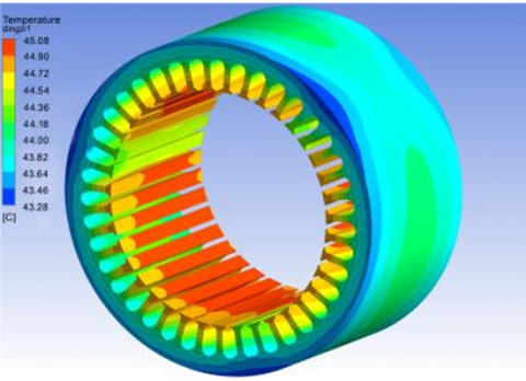
Figure 3 shows the temperature distribution of stator core under normal conditions and different kinds of demagnetization fault. The stator core was significantly cooler than the windings. For the entire stator core, the temperature peaked on the stator teeth, and gradually fell from the teeth to the outer surface.
(a) Normal conditions
(b) Symmetric two-block 50% demagnetization
(c) Single-block 50% demagnetization
(d) Single-block complete demagnetization
Figure 3. Temperature distribution of stator core under normal conditions and demagnetization fault
As shown in Figures 3(b) and 3(c), the temperature under symmetric two-block 50% demagnetization was 0.48% lower than that under single-block 50% demagnetization, because the core loss under the former is smaller than that under the latter.
4.3 Temperature distribution and variation law of permanent magnets
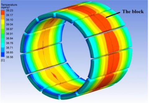
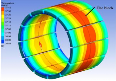
High temperature is a primary cause of the demagnetization of permanent magnets. Thus, it is important to study the temperature of permanent magnets under demagnetization fault. Figure 4 shows the temperature distribution of permanent magnets under normal conditions and different kinds of demagnetization fault. The temperature of permanent magnets gradually decreases from the center to both ends, with the peak at the center surface. The occurrence of the demagnetization fault suppressed the overall temperature of permanent magnets, and the temperature drop increased with the demagnetization degree. Specifically, the temperature under symmetric two-block 50% demagnetization was 3.6% lower than that under single-block 50% demagnetization. The temperature drop of permanent magnets was deeper than that of windings and stator core undergoing the same change of demagnetization faults. This is attributable to the dominant temperature rise effect of the eddy current loss of permanent magnets. Moreover, the eddy current loss under symmetric two-block 50% demagnetization was smaller than that under single-block 50% demagnetization, and similar to that under single-block complete demagnetization. Hence, symmetric two-block 50% demagnetization and single-block complete demagnetization bore a resemblance in temperature distribution.
(a) Normal conditions
(b) Symmetric two-block 50% demagnetization
(c) Single-block 50% demagnetization
(d) Single-block complete demagnetization
Figure 4. Temperature distribution of permanent magnets under normal conditions and demagnetization fault
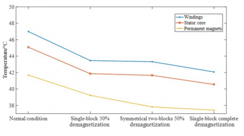
Figure 5 shows the peak temperature variation of windings, stator core, and permanent magnets with demagnetization degrees. The windings were always hotter than the stator core and permanent magnets, whether under normal conditions or demagnetization fault. The peak temperature of the three parts of the generator plunged with the growing demagnetization degree. The peak temperatures of windings, stator core, and permanent magnets under single-block 50% demagnetization were 0.32%, 0.48%, and 3.6% lower than those under symmetric two-block 50% demagnetization, respectively; the peak temperatures of windings, stator core, and permanent magnets under symmetric two-block 50% demagnetization were 2.97%, 2.74%, and 1.07% higher than those under single-block complete demagnetization, respectively.
Figure 5. Peak temperature variation of windings, stator core, and permanent magnets with demagnetization degrees
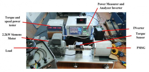
To validate our simulation model and verify the temperature distribution law, a temperature rise experiment was carried out on the generator. Figure 6 presents the designed experimental platform. The turbine is a 2.2kW variable frequency Siemens motor. The generator is powered by a three-phase rectification process to supply a 20Ω pure resistive load, and works at 500 rpm under the ambient temperate of 20℃. The generator speed was regulated by an inverter, and captured by a torque and speed power tester. Two PT100 thermal resistance temperature sensors were embedded in the outer surface of the windings and the stator yoke, respectively. The temperatures of these two parts were measured after the temperature of the generator stabilized. Table 4 lists the experimental results.
Figure 6. Our temperature rises experimental platform
Table 4. Experimental results
|
|
Fault type |
Windings |
Stator yoke |
|
Simulated value (℃) |
Normal conditions |
46.99 |
43.28 |
|
Single-block 50% demagnetization |
43.46 |
40.31 |
|
|
Symmetric two-block 50% demagnetization |
43.32 |
40.11 |
|
|
Experimental value (℃) |
Normal condition s |
45.8 |
43.1 |
|
Single-block 50% demagnetization |
42.1 |
36.1 |
|
|
Symmetric two-block 50% demagnetization |
42.3 |
41.1 |
|
|
Error (%) |
Normal conditions |
2.5 |
0.4 |
|
Single-block 50% demagnetization |
3.2 |
1.3 |
|
|
Symmetric two-block 50% demagnetization |
2.4 |
-2.4 |
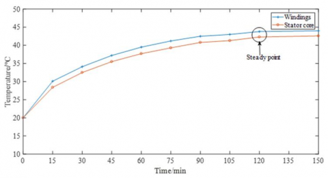
Figure 7. Temperature rise curves of the PMSG under symmetric two-block 50% demagnetization
As shown in Table 4, the simulated temperatures were slightly above the experimental ones under different kinds of demagnetization fault. This is because the heat dissipation coefficients in the simulation are calculated empirically, and the losses in the 3D temperature field model were calculated by simulation. Besides, there was a certain error in the loss of the generator. The simulated temperature deviated from the experimental temperature by less than 4%, a sign of the high reliability of the simulation. Figure 7 presents the temperature rise curves of the PMSG under symmetric two-block 50% demagnetization. After two hours of generator operation, the temperature of windings and stator core changed slowly, and tended to be stable.
Targeting a 1kW PMSG, this paper carries out finite-element electromagnetic field analysis and experiment to calculate the copper loss of windings, stator core loss, and eddy current loss of permanent magnets under normal conditions and different kinds of demagnetization fault. Specifically, the thermal conductivity of materials was determined, as well as the natural heat transfer coefficient of the casing surface. Then, the authors established a 3D temperature field model for the generator under demagnetization fault, and derived the relationship between the temperatures of windings, stator core and permanent magnets, and demagnetization degree. Finally, the 3D temperature field model was verified through a temperature rise experiment. The main conclusions are as follows:
(1) The temperature rise of the generator is related to the loss. The temperature rise effect mainly depends on the copper loss of windings. In the event of the demagnetization fault, the temperatures of the windings, stator core, and permanent magnets all decrease, and the temperature drop is positively correlated with the demagnetization degree.
(2) The temperature rise effect of permanent magnets is mainly determined by eddy current loss, and partly affected by the copper loss of the windings.
(3) The growing demagnetization degree magnifies the temperature drop of windings, stator core, and permanent magnets, because the copper loss of windings, stator core loss, and eddy current loss of permanent magnets decrease with the rising demagnetization degree.
(4) Concerning the temperature variation law of the generator under demagnetization fault, the experimental result was basically consistent with the simulated result, with an error within -2.4%~3.2%. Hence, the observed temperature variation law provides a theoretical basis for determining demagnetization fault.
This work was supported in part by the National Natural Science Foundation of China General Project (Grant No.: 52177063) and the Scientific and Technological Project of Henan Province, China (Grant No.: 212102210019).
[1] Lam, K.C., Cai, C.M., Dai, J.P., Li, X.H. (2020). Hong Kong in the Belt and Road Initiative. The Chinese University of Hong Kong Press.
[2] Kim, D.W., Kim, C.H., Kim, J.S., Kim, Y.J., Jung, S.Y. (2020). Operation characteristic of IPMSM considering PM saturation temperature. IEEE Transactions on Applied Superconductivity, 30(4): 1-4. https://doi.org/10.1109/TASC.2020.2989799
[3] Bounasla, N., Barkat, S. (2020). Optimum design of fractional order PIᵅ speed controller for predictive direct torque control of a sensorless five-phase Permanent Magnet Synchronous Machine (PMSM). Journal Européen des Systèmes Automatisés, 53(4): 437-449. https://doi.org/10.18280/jesa.530401
[4] Verkroost, L., Vansompel, H., De Belie, F., Sergeant, P. (2020). Comparison between two fault tolerant deadbeat controllers under partial demagnetization faults in permanent magnet synchronous machines. In 2020 International Conference on Electrical Machines (ICEM), 1: 074-1080. https://doi.org/10.1109/ICEM49940.2020.9271005
[5] Kobayashi, M., Morimoto, S., Sanada, M., Inoue, Y. (2020). Influence of variation of recoil permeability of bonded magnets on demagnetization characteristics of permanent magnet assisted synchronous reluctance motor. In 2020 23rd International Conference on Electrical Machines and Systems (ICEMS), pp. 1568-1573. https://doi.org/10.23919/ICEMS50442.2020.9290803
[6] Drancă, M., Chirca, M., Breban, Ş., Fărtan, M. (2020). Thermal and demagnetization analysis of an axial-flux permanent magnet synchronous machine. In 2020 International Conference and Exposition on Electrical and Power Engineering (EPE), pp. 200-204. https://doi.org/10.1109/EPE50722.2020.9305576
[7] Zhao, J., Wang, L., Xu, L., Dong, F., Song, J., Yang, X. (2021). Uniform demagnetization diagnosis for permanent-magnet synchronous linear motor using a sliding-mode velocity controller and an ALN-MRAS flux observer. IEEE Transactions on Industrial Electronics, 69(1): 890-899. https://doi.org/10.1109/TIE.2021.3050360
[8] Wang. H., Wang. N., Yang. S.Y. (2013). Numerical calculations of the coupled eddy current-temperature fields in the end regions of large hydro-generator using magnet and thermnet software. Transactions of China Electrotechnical Society, 28(2): 116-120.
[9] Shi, J., Wei, D., Mou. X.S. (2015). Three-dimensional temperature field analysis and calculation for automobile alternators. Micromotors, 48(5): 41-46.
[10] Liang, Y., Wu, L., Bian, X., Wang, C. (2016). Influence of void transposition structure on the leakage magnetic field and circulating current loss of stator bars in water-cooled turbo-generators. IEEE Transactions on Industrial Electronics, 63(6): 3389-3396. https://doi.org/10.1109/TIE.2016.2521719
[11] Kang, L.L., Jiang, D.J., Sun, S.H. (2018). Thermal field research of permanent magnet synchronous generator for rail vehicles with internal combustion. Micromotors, 51(11): 13-17. https://doi.org/10.3969/j.issn.1001-6848.2018.11.003
[12] Chowdhury, S.K., Baski, P.K. (2010). A simple lumped parameter thermal model for electrical machine of TEFC design. In 2010 Joint International Conference on Power Electronics, Drives and Energy Systems & 2010 Power India, pp. 1-7. https://doi.org/10.1109/PEDES.2010.5712385
[13] Ma, H.H., Chen, T.T., Shi, W.J. (2013). Analysis and calculation on three-dimensional temperature field of brush and slip ring systems for wind generators. Proceedings of the CSEE, 33(30): 98-105.
[14] Song, X., Zhao, J., Song, J., Dong, F., Xu, L., Zhao, J. (2020). Local demagnetization fault recognition of permanent magnet synchronous linear motor based on S-transform and PSO–LSSVM. IEEE Transactions on Power Electronics, 35(8): 7816-7825. https://doi.org/10.1109/TPEL.2020.2967053
[15] Zhang, C., Chen, L., Wang, X., Tang, R. (2020). Loss calculation and thermal analysis for high-speed permanent magnet synchronous machines. IEEE Access, 8: 92627-92636. https://doi.org/10.1109/ACCESS.2020.2994754
[16] Zhu, G.J., Zhu, Y.H., Tong, W.M., Han, X.Y., Zhu, J.G. (2017). Thermal analysis techniques of finite formulation method and the application on permanent magnet machines. Proceedings of the CSEE, 37(1): 152-161. https://doi.org/10.13334/j.0258-8013.pcsee.170781
[17] De Bisschop, J., Vansompel, H., Sergeant, P., Dupre, L. (2017). Demagnetization fault detection in axial flux PM machines by using sensing coils and an analytical model. IEEE Transactions on Magnetics, 53(6): 1-4. https://doi.org/10.1109/TMAG.2017.2669480
[18] Yu, Y., Hao, Z., Bi, Y., Pei, Y. (2019). 22nd international conference on electrical machines and systems. ICEMS, pp. 1-7.
[19] Hu, T., Tang, R.Y., Li, Y. (2013). Three-dimensional temperature field analysis and calculation of permanent magnet wind generators. Transactions of China Electrotechnical Society, 28(3): 122-126.
[20] Cao, X.H., Wei, H., Wang, X. (2018). Parameter identification method of permanent magnet synchronous motor considering temperature influence. Journal of South China University of Technology (Natural Science Edition), 46(8): 64-71. https://doi.org/10.3969/j.issn.1000-565X.2018.08.010
[21] Qiu, H.B., Duan, Q., Feng, J.Q. (2017). Influence of winding distribution on the electromagnetic field and temperature field of permanent magnet servo machine. Electrical Measurement & Instrumentation, 54(1): 105-111. https://doi.org/10.3969/j.issn.1001-1390.2017.01.019