Hamza Al-Tahaineh* | Mohamad H. Okour | M. Al-Rashdan | Fayez M.S. Al Essa
© 2022 IIETA. This article is published by IIETA and is licensed under the CC BY 4.0 license (http://creativecommons.org/licenses/by/4.0/).
OPEN ACCESS
In this article, a single stage ammonia-water absorption refrigeration cycle integrated with thermoelectric power generators driven by evacuated tube solar collectors is presented and investigated. The working fluid is ammonia-water solution, and the hybrid system was modeled, and analyzed using EES software. The system coefficient of performance (COP) was found to increase with increasing the generator temperature. From the results obtained, when the cycle operated with 0.99 ammonia mass fraction, it was found that the best location of the thermoelectric generators is at the rectifier between the generator and the condenser where the value of COP exceeds 0.82 at temperature difference across the TEG of 60℃. The other locations, between condenser-evaporator and evaporator-absorber, show similar performance.
absorption refrigeration, coefficient of performance (COP), thermoelectric generator (TEG), energy recovery, mass fraction
In both home and industrial applications, the absorption cycle is one of the most promising techniques to utilize solar heat to cool spaces. Absorption cooling was not widely available for small-capacity applications until recently, and it was more expensive than typical vapor compression cooling. There are two basic types of absorption cooling cycles based on the working fluid which are Lithium Bromide-Water (LiBr-H2O) and Ammonia-Water (NH3-H2O) [1].
The idea behind thermoelectric principle is the transforming of thermal energy into electrical energy, and vice versa. The thermoelectric device, when functioning as an energy generating device, is called a thermoelectric generator (TEG) [2]. Although TEG device is considered as a thermal energy collecting device, it could also be used as coolant sensor due to reversible properties nature specifically for high temperature difference applications [3].
A heat energy generator is a semiconductor device which convert heat energy into electrical energy through an effect called the Seebeck effect. To form a thermocouple, n- and p-type semiconductor thermocouple elements are connected in series to a metal of high conductivity. Each thermocouple side maintains a different temperature for charge flow from the n-type thermocouple side to the p-type side, resulting in a potential difference [4, 5]. The Seebeck effect is the process of flowing charge carriers such as electrons and Holes in n-type and p-type semiconductor as shown in Figure 1; therefore, it is a direct energy transfer from thermal to electric. The commonly used materials are bismuth telluride (bi2te3), lead telluride (PbTe) and silicon germanium (Sige) [6].
A Peltier device created by Amir Abdullah Muhamad Damanhuri, et al. was used to recover heat from a condensing unit and generate energy from it. Copper sandwich plates (120mm×60mm×2mm) were sandwiched between the discharge pipe of the compressor and the heat sink, while condensing water from the evaporator flowed through the opposite side. Temperature differences of roughly 10℃ across the TEG with 1.61 V are regarded prospective applications of TEGs for heat recovery after operating the AC for about half an hour [7].
Nowadays, thermoelectric technology such as thermoelectric cooling systems (TECs) and thermoelectric generators (TEGs) can give the chance to recover the heat loss of thermodynamic systems to produce power in remotes areas while there is unlimited solar energy that can be used to produce the power. The fact that the ability of thermoelectric technologies to produces electricity from in-system sources which can be used for different applications; is the most interesting feature; because the using of this produced electricity will save a lot of cost that is spend in different things such as driving the system. Thermoelectric generators and coolers have a wide range of uses, including medical instruments, industry machines, electronic devices, and transportation tools. Heat pumps and power generators have a user-friendly application. For renewable energy applications, it is used to generate electric power from waste energy during the heating or cooling process [8, 9].
Figure 1. Thermoelectric generator charge carriers [6]
He et al. [10] described the modern applications of thermoelectric cooler (TEC) and thermoelectric generator (TEG) including the equipment enhancement which clearly effect the performance of (TEG) and (TEC). Moh'd and Al-Ammari [11] investigated a solar distillation system with thermoelectric generator and found that an efficiency of (15-25%) could be provided by a (400-800) W/m2 solar radiation, distillate of (1.5-3) kg/day and a (TEG) efficiency of (0.6-1.5%).
Kizilkan et al. [12] studied a power cycle using absorption refrigeration system with thermoelectric generator (TEG) and powered by waste energy. Their results showed that the energy and exergy efficiencies of the module provided generate of 4.81-kw electric power.
Tashtoush and Qassim [13] investigated a 20-kw single stage absorption cycle using water-Lithium bromide (H2O-LiBr) solution as the working fluid and powered by a solar evacuated tube collector with installing TEG and TEC. Their results showed that a 20% increasing in the generator temperature will improve the power produced by the (TEG) modules by 60%, as well as an increasing in the (TEG) modules of 20% will reduce the efficiency of (TEG) by 11.5%.
Studying more applications of TEGs in (HVAC) systems was performed by many researchers [14-16], electric power generation from exhaust air heat recovery process and condenser hot air energy [17], and heat lost recovery in split unit air conditioners [18]. A novel integrated solar power generation based on Rankine cycle and absorption refrigeration system were studied by Kizilkan et al. [19].
In this article, a detailed thermodynamic analysis of a hybrid TEG/single stage ammonia-water absorption refrigeration cycle with a combined effect of rectifier and condensate precooler driven by evacuated tube solar collectors is presented and investigated. The effect of ammonia mass fraction and generator temperature on the COP of the system is to be studied and the best location to install the TEG in the cycle was one of the main goals.
The simple single-stage ammonia/water absorption refrigeration cycle suffer from low COP as compared to LiBr/water absorption cycle which is in general lower than 0.5. Several opportunities are considered to improve the performance of the absorption system including using rectifier to ensure the purity of the refrigerant leaving the generator by increasing its mass fraction to approach unity. Minimizing the thermal losses within the cycle also has a considerable effect on the performance, and the simplest way to accomplish this is to reuse heat within the cycle. Recovering lost heat within the cycle is often accomplished by using an internal heat exchanger. One of the simplest applications is the use of refrigerant heat exchanger to subcool the refrigerant leaving the condenser using the cooled refrigerant leaving the evaporator, thereby the stream entering the absorber will be heated. This heat exchanger is called condensate precooler which enhance the COP of the cycle slightly above 0.5 [20].
A single stage ammonia-water absorption refrigeration cycle with a with a rectifier and condensate precooler shown in Figure 2 is studied with installing TEG modules at different location of the absorption cycle. Ammonia is the refrigerant of the cycle and is generated from the desorber which is driven by evacuated tube solar collector. The cycle was examined using EES for different ammonia mass fraction (Xref.) and different temperature difference across the TEG modules. The main external power to drive the system is the heat attained by evacuated tube solar collector which considered as an excellent device to supply the system with energy and temperature required.
Figure 2. Single stage ammonia-water absorption refrigeration cycle with a rectifier and condensate precooler with TEG installed at prescribed locations
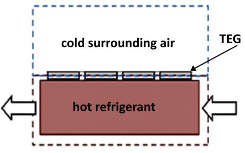
The main locations to install the TEG modules are at rectifier between desorber-condenser, at condensate precooler between condenser-evaporator, and between evaporator-absorber where the temperature difference with the surrounding is expected to be high enough to generate electric power using TEG modules shown in Figure 3 which operate between hot refrigerant and cold surrounding air.
Figure 3. Schematic of TEG module used in the absorption cycle
Energy balance of all the components of the single stage ammonia-water absorption refrigeration cycle with a with a rectifier and condensate precooler is carried out based on the first law of thermodynamics. several assumptions were taken when constructing the mathematical model, which include [21]:
(1) steady state and steady flow conditions.
(2) changes in potential and kinetic energies across each component of the system are negligible.
(3) negligible pressure drop due to friction or heat loss.
(4) heat flux is 1D.
(5) evacuated tube solar collector is just used as an external heat supply to drive the cycle and not considered in analysis of the system.
Following the analysis of the absorption systems done by Harold [20]. The mass and energy balance equations could be applied on each component, as a control volume, of the system shown in Figure 2 as follow:
Generator (Desorber)
Total mass balance:
$\dot{m}_{3}=\dot{m}_{4}+\dot{m}_{9}$ (1)
Refrigerant mass balance:
$\dot{m}_{3} X_{3}=\dot{m}_{4} X_{4}+\dot{m}_{9} X_{9}$ (2)
From the generator mass balance, the mass flow rate of strong and weak solutions $\dot{m}_{3}$ and $\dot{m}_{4}$ are given respectively in terms of mass fraction ratios as:
$\dot{m}_{3}=\frac{X_{9}-X_{4}}{X_{3}-X_{4}} \cdot \dot{m}_{9}$ (3)
$\dot{m}_{4}=\frac{X_{3}-X_{9}}{X_{4}-X_{3}} \cdot \dot{m}_{9}$ (4)
From the Eq. (3), the circulation ratio is given by:
$f=\frac{\dot{m}_{3}}{\dot{m}_{9}}=\frac{X_{9}-X_{4}}{X_{3}-X_{4}}$ (5)
Energy balance:
$\dot{Q}_{d}=\dot{m}_{4} h_{4}+\dot{m}_{9} h_{9}-\dot{m}_{3} h_{3}$ (6)
$\dot{Q}_{d}=\dot{m}_{18} C_{p}\left(T_{18}-T_{19}\right)$ (7)
$\dot{Q}_{d}=(U \cdot A)_{g} \cdot\left(\Delta T_{L M T D}\right)_{g}$ (8)
where, Log Mean Temperature Difference (LMTD) for the generator as a counter flow heat exchanger is given by:
$L M T D_{d}=\frac{\left(T_{18}-T_{4}\right)-\left(T_{19}-T_{9}\right)}{\ln \left(\frac{T_{18}-T_{4}}{T_{19}-T_{9}}\right)}$ (9)
Absorber
In this part the refrigerant (ammonia vapor) from evaporator and the ammonia-weak solution are mixed, and the heat is released. The mass and energy balance are given respectively:
$\dot{m}_{1}=\dot{m}_{6}+\dot{m}_{14}$ (10)
$\dot{Q}_{a}=\dot{m}_{5} h_{5}+\dot{m}_{14} h_{14}-\dot{m}_{1} h_{1}$ (11)
$\dot{Q}_{a}=\dot{m}_{16} C_{p}\left(T_{17}-T_{16}\right)$ (12)
$\dot{Q}_{a}=(U \cdot A)_{a} \cdot\left(\Delta T_{L M T D}\right)_{a}$ (13)
where, the absorber LMTDa is given by:
$L M T D_{a}=\frac{\left(T_{6}-T_{17}\right)-\left(T_{1}-T_{16}\right)}{\ln \left(\frac{T_{6}-T_{17}}{T_{1}-T_{16}}\right)}$ (14)
Condenser
The refrigerant los heat to the surrounding to transform to saturated liquid, the equations of the heat rejected in the condenser are:
$\dot{Q}_{c}=\dot{m}_{9} h_{9}-\dot{m}_{10} h_{10}$ (15)
$\dot{Q}_{c}=\dot{m}_{20} C_{p}\left(T_{21}-T_{20}\right)$ (16)
$\dot{Q}_{c}=(U \cdot A)_{c} \cdot\left(\Delta T_{I M T D}\right)_{c}$ (17)
where, the condenser LMTDc is given by:
$L M T D_{c}=\frac{\left(T_{20}-T_{10}\right)-\left(T_{21}-T_{10}\right)}{\ln \left(\frac{T_{20}-T_{10}}{T_{21}-T_{10}}\right)}$ (18)
Evaporator
The heat absorbed by the refrigerant in the evaporator represents the cooling capacity of the system for which the ACS were designed. The thermodynamic analysis and the cooling capacity of the evaporator are given as follow:
$\dot{Q}_{e}=\dot{m}_{13} h_{13}-\dot{m}_{12} h_{12}$ (19)
$\dot{Q}_{e}=\dot{m}_{22} C_{p}\left(T_{22}-T_{23}\right)$ (20)
$\dot{Q}_{e}=(U \cdot A)_{e} \cdot\left(\Delta T_{L M T D}\right)_{e}$ (21)
where, the evaporator LMTDe is given by:
$L M T D_{e}=\frac{\left(T_{22}-T_{13}\right)-\left(T_{23}-T_{12}\right)}{\ln \left(\frac{T_{22}-T_{13}}{T_{23}-T_{12}}\right)}$ (22)
Expansion valves
The expansion devices are used to reduce the pressure of the fluid to the required pressure; and as a result, the temperature decreases while keeping the enthalpy of the fluid constant in an isenthalpic throttling process. The cycle contains two expansion valves, solution and refrigerant expansion valves.
Mass and energy balance for solution expansion valve (SEV):
$\dot{m}_{5}=\dot{m}_{6}$ (23)
$h_{5}=h_{6}$ (24)
Mass and energy balance for refrigerant expansion valve (REV):
$\dot{m}_{10}=\dot{m}_{11}=\dot{m}_{12}=\dot{m}_{r e f}$ (25)
$h_{11}=h_{12}$ (26)
Pump
The power required to operate the pump $\dot{W}_{p}$ is too so small compared to the other components energy in the system and usually neglected. The mass and energy balance of the pump:
$\dot{m}_{1}=\dot{m}_{2}$ (27)
$\dot{W}_{p}=m_{1}\left(h_{2}-h_{1}\right)$ (28)
Rectifier
The overall mass balance of the rectifier is:
$\dot{m}_{7}=\dot{m}_{8}+\dot{m}_{9}$ (29)
The refrigerant mass balances:
$\dot{m}_{7} X_{7}=\dot{m}_{8} X_{8}+\dot{m}_{9} X_{9}$ (30)
From the mass balance, the refrigerant recirculation ratio, r, is defined as:
$r=\frac{\dot{m}_{9}}{\dot{m}_{7}}$ (31)
The heat of rectification is given by:
$Q_{\text {rec }}=\dot{m}_{7}\left[\left(h_{7}-h_{8}\right)+r\left(h_{8}-h_{9}\right)\right]$ (32)
Heat exchangers
The system contains two heat internal heat exchangers, solution and refrigerant (Condensate precooler) heat exchangers. The energy balance equations and the effectiveness of the solution heat exchanger (SHX) are given respectively in Eqns. (33) and (34):
$\dot{Q}_{S H X}=\dot{m}_{4}\left(h_{4}-h_{5}\right)=\dot{m}_{3}\left(h_{3}-h_{15}\right)$ (33)
$\varepsilon_{S H X}=\frac{\left(T_{4}-T_{5}\right)}{\left(T_{4}-T_{15}\right)}$ (34)
The energy balance equation for refrigerant heat exchanger (RHX) (Condensate precooler) is given in Eq. (35) as:
$\dot{Q}_{R H X}=\dot{m}_{10}\left(h_{10}-h_{11}\right)=\dot{m}_{14}\left(h_{14}-h_{13}\right)$ (35)
The effectiveness of the RHX is given by:
$\varepsilon_{R H X}=\frac{\left(T_{10}-T_{11}\right)}{\left(T_{10}-T_{13}\right)}$ (36)
Coefficient of performance
The COP of the ACS is defined as the ratio of desired output to the energy input:
$C O P_{A C S}=\frac{\dot{Q}_{e}}{\dot{Q}_{g}+\dot{W}_{p}}$ (37)
Thermoelectric generator
For the two sides of TEG module, the heat absorbed at the hot side (QH) and the heat rejected at the cold side (QC) are given in Eqns. (38) and (39) respectively:
$Q_{H}=K\left(T_{H}-T_{C}\right)+\alpha_{p N} I T_{H}-0.5 I^{2} R$ (38)
$Q_{C}=K\left(T_{H}-T_{C}\right)+\alpha_{v N} I T_{C}-0.5 I^{2} R$ (39)
where, I is the current, α is the Peltier coefficient. K and R are respectively the total thermal conductivity and resistance which may be given in terms of semiconductor resistivity ρ, length L, and cross-sectional area A by Eqns. (40) and (41):
$K=\frac{k_{p} \cdot A_{p}}{L_{p}}+\frac{k_{N} \cdot A_{N}}{L_{N}}$ (40)
$R=\frac{\rho_{p} \cdot L_{p}}{A_{p}}+\frac{\rho_{N} \cdot L_{N}}{A_{N}}$ (41)
The electrical power generated by the TEG, P is simply the difference between heat absorbed and heat rejected as given by Eq. (42):
$P=Q_{H}-Q_{C}=V_{L} I$ (42)
where, VL is the voltage across the connected load.
Since VL=IRL and R=Rp+RN, the TEG generated power could be rewritten as:
$P=\alpha_{p N} I\left(T_{H}-T_{C}\right)-I^{2} R$ (43)
where, the current I is given by:
$I=\frac{\alpha_{p N}\text{ }\left(T_{H}-T_{C}\right)}{R_{p}+R_{N}+R_{L}}$ (44)
The efficiency of TEG is defined as the ratio of power generated to the amount of heat absorbed at the hot side of the TEG:
$\eta=\frac{P}{Q_{H}}$ (45)
The overall efficiency of the ACS with TEG installation [13]:
$C O P=\frac{Q_{e}+P}{Q_{G}+W_{P}}$ (46)
The mathematical model of the present work was validated by applying it on single-stage ammonia-water absorption cycle published by Herold [20]. For the same temperature, pressure, and mass fraction as input data for the current model, the enthalpy was calculated using EES and compared to that obtained by Herold as shown in Tables 1 and 2.
Table 1. Single-stage ammonia/water cycle for current model as compared to Herold [20]
|
Temperature (K) |
Pressure (bar) |
Mass dry fraction (kg/kg) |
Enthalpy (kJ/kg) |
|
|
Published model |
Current model |
|||
|
313.15 |
1.328 |
0.2811 |
-9.2 |
-8.597 |
|
313.15 |
15.4 |
0.2811 |
-7.6 |
-7.557 |
|
395.65 |
15.4 |
0.2811 |
356.2 |
356.1 |
|
425.55 |
15.4 |
0.1811 |
538.6 |
538.5 |
|
348.25 |
15.4 |
0.1811 |
196.5 |
196.3 |
|
337.45 |
1.328 |
1811 |
196.5 |
198 |
|
400.55 |
15.4 |
0.8736 |
1674 |
1674 |
|
400.55 |
15.4 |
0.2811 |
378.6 |
379.4 |
|
349.65 |
15.4 |
0.99 |
1410 |
1415 |
|
313.15 |
15.4 |
0.99 |
184.1 |
183.6 |
|
286.65 |
15.4 |
0.99 |
55.9 |
56.01 |
|
245.65 |
1.328 |
0.99 |
55.9 |
343.3 |
|
263.15 |
1.328 |
0.99 |
1234 |
1234 |
|
298.55 |
1.328 |
0.99 |
1362 |
1362 |
|
328.05 |
15.4 |
0.2811 |
56.4 |
56.34 |
Table 2. Energy results for single stage ammonia/water cycle as compared to Herold [20]
|
|
$\dot{W}_{\mathrm{p}}(\mathrm{kW})$ |
$\dot{Q}_{\mathrm{shx}}(\mathrm{kW})$ |
$\dot{Q}_{\text {rec }}(\mathrm{kW})$ |
$\dot{Q}_{\operatorname{des}}(\mathrm{kW})$ |
|
Published model |
1.6 |
299.8 |
64 |
354.1 |
|
Current model |
1.04 |
299.7 |
64.76 |
354.3 |
|
|
$\dot{Q}_{\text {abs }}(\mathrm{kW})$ |
$\dot{Q}_{\text {cond }}(\mathrm{kW})$ |
$\dot{Q}_{\mathrm{eva}}(\mathrm{kW})$ |
COP |
|
Published model |
349.8 |
151.6 |
145.6 |
0.409 |
|
Current model |
350.9 |
152.7 |
110.5 |
0.4118 |
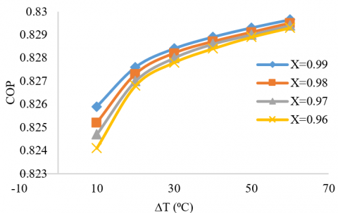
To show the effect of TEG installation on the whole system performance, the COP of the absorption cycle was calculated first without installing TEG modules. Figure 4 shows the variation of cycle COP with temperature difference across the rectifier between generator and condenser for different ammonia mass fraction (without TEG installation). Results show that COP increase as the refrigerant ammonia get more purified. But, for best case with mass fraction of 0.99, the COP never exceed 0.55 and get lower for lower mass fractions. Installing TEG on the rectifier between generator and condenser significantly enhance the cycle COP as shown in Figure 5 by about 51% where the maximum value reached 0.83 for ammonia mass fraction of 0.99.
Figure 4. Variation of COP with temperature difference across the rectifier between generator and condenser for different refrigerant mass fraction (without installing TEGs)
Figure 5. Variation of COP with temperature difference for different refrigerant mass fraction with installing TEGs between desorber and condenser
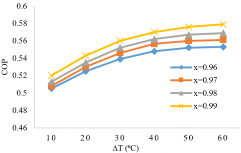
Figure 6. Variation of COP with temperature difference for different refrigerant mass fraction with installing TEGs between condenser and evaporator
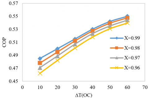
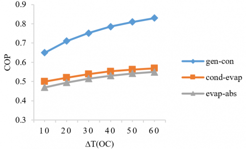
Figures 5-7 show the absorption system COP with installing TEG modules at different location with the cycle. The system shows best performance when augmenting TEGs with rectifier located between desorber and condenser since the temperature difference was maximum as shown in Figure 5. The results obtained show that the cycle performance was affected by temperature difference across the TEG and the mass fraction of the refrigerant (ammonia), and COP was found to increase with increasing both. The next optimum location for installing TEGs on condensate precooler (CP) was between condenser and evaporator where the COP reached 0.57 for ammonia mass fraction of 0.99 while its value was 0.55 when installing the TEGs between evaporator and absorber. Figure 8 show the variation of the whole system COP for the three different locations discussed above. It’s clearly shown that TEGs significantly enhance the COP of the single stage ammonia-water absorption refrigeration cycle with a rectifier and condensate precooler when augmented with rectifier.
Figure 7. Variation of COP with temperature difference for different refrigerant mass fraction with installing TEGs between evaporator and absorber
Figure 8. Variation of COP with temperature difference when installing TEGs at different locations in the system for refrigerant mass fraction, x=0.99
The installation of TEG modules at three distinct locations of a single stage ammonia-water absorption refrigeration cycle with a rectifier and condensate precooler was investigated in this study. The rectifier between the desorber and the condenser was the first placement. Between the condenser and the evaporator, and between the evaporator and the absorber, respectively, the second and third positions.
This study could be one of the first to look into the impact of adding TEGs to absorption systems. The current study's findings clearly show that such TEGs applications have a strong potential for solar absorption systems and waste energy recovery. The results reveal that adding TEG modules to the rectifier boosts the absorption cycle's COP by roughly 51%, with a maximum value of 0.83 for an ammonia mass fraction of 0.99 at a temperature differential of 60℃ across the TEG. The other positions, between the condenser and the evaporator, perform similarly, with maximum COPs of 0.57 and 0.55, respectively.
|
A |
surface area (mm2) |
|
An |
cross sectional area of n-type legs junctions (mm2) |
|
Ap |
cross sectional area of p-type legs junctions (mm2) |
|
ACS |
absorption cooling system |
|
COP |
coefficient of performance |
|
Cp |
specific heat (J/kg.K) |
|
ETC |
evacuated tube collector |
|
h |
enthalpy (kJ/kg) |
|
I |
electrical current (A) |
|
K |
thermal conductivity (W/m.k) |
|
CV |
controlled volume |
|
LMTD |
Log Mean Temperature Difference |
|
Ln |
length of n-type legs (mm) |
|
Lp |
length of p-type legs (mm) |
|
$\dot{m}$ |
mass flow rate (kg/s) |
|
P |
electric power generated by TEG (W) |
|
$\dot{Q}$ |
heat transfer rate (kW) |
|
SHX |
Solution Heat Exchanger |
|
Tam |
ambient temperature (K) |
|
TL |
cold temperature(K) |
|
TH |
high temperature(K) |
|
TEG |
Thermoelectric Generator |
|
U |
overall heat transfer coefficient (W/m2.k) |
|
VAC |
Vapor Absorption Cooling |
|
Wp |
pump work (kW) |
|
V |
voltage |
|
r |
refrigerant circulation ratio |
|
f |
circulation ratio |
|
Greek symbols |
|
|
$\eta$ |
efficiency |
|
$\alpha_{p-n}$ |
Peltier Coefficient of n-type and p-type semiconductor |
|
$\mathcal{\varepsilon}$ |
effectiveness |
|
ρn & ρp |
electrical resistivity of n-type and p-type semiconductor (Ω.cm) |
[1] Desideri, U., Asdrubali, F. (2018). Handbook of Energy Efficiency in Buildings: A Life Cycle Approach. Butterworth-Heinemann.
[2] Taylor, R.A., Solbrekken, G.L. (2008). Comprehensive system-level optimization of thermoelectric devices for electronic cooling applications. IEEE Transactions on Components and Packaging Technologies, 31(1): 23-31. https://doi.org/10.1109/TCAPT.2007.906333
[3] MacDonald, D.K.C. (2006). Thermoelectricity: An Introduction to the Principles. Courier Corporation.
[4] Enescu, D. (2019). Thermoelectric energy harvesting: Basic principles and applications. Green Energy Advances. https://doi.org/10.5772/intechopen.83495
[5] Jaziri, N., Boughamoura, A., Müller, J., Mezghani, B., Tounsi, F., Ismail, M. (2020). A comprehensive review of thermoelectric generators: Technologies and common applications. Energy Reports, 6: 264-287. https://doi.org/10.1016/j.egyr.2019.12.011
[6] Sreekala, P., Ramkumar, A., Rajesh, K. (2019). Thermo electric generator fed LVDC system analyzed with non linear loads. In 2019 IEEE International Conference on Clean Energy and Energy Efficient Electronics Circuit for Sustainable Development (INCCES), pp. 1-4. https://doi.org/10.1109/INCCES47820.2019.9167705
[7] Damanhuri, A.A.M., Abdullah, M.I.H.C., Lubis, A.M.H.S., Zakaria, M.Z., Hussin, M.S.F., Kasno, M.A. (2018). Development of TEG Peltier device for heat harvesting from 1.5 HP split unit air conditioning system. International Journal of Applied Engineering Research, 13(5): 2390-2394.
[8] Sulaiman, A.C., Amin, N.A.M., Basha, M.H., Majid, M.S.A., bin Mohd Nasir, N.F., Zaman, I. (2018). Cooling performance of thermoelectric cooling (TEC) and applications: A review. In MATEC Web of Conferences, 225: 03021. https://doi.org/10.1051/matecconf/201822503021
[9] Cao, Q., Luan, W., Wang, T. (2018). Performance enhancement of heat pipes assisted thermoelectric generator for automobile exhaust heat recovery. Applied Thermal Engineering, 130: 1472-1479. https://doi.org/10.1016/j.applthermaleng.2017.09.134
[10] He, W., Zhang, G., Zhang, X., Ji, J., Li, G., Zhao, X. (2015). Recent development and application of thermoelectric generator and cooler. Applied Energy, 143: 1-25. https://doi.org/10.1016/j.apenergy.2014.12.075
[11] Moh'd, A., Al-Ammari, W. (2017). Utilizing the evaporative cooling to enhance the performance of a solar TEG system and to produce distilled water. Solar Energy, 146: 209-220. https://doi.org/10.1016/j.solener.2017.02.037
[12] Kizilkan, O., Khanmohammadi, S., Saadat-Targhi, M. (2019). Solar based CO2 power cycle employing thermoelectric generator and absorption refrigeration: Thermodynamic assessment and multi-objective optimization. Energy Conversion and Management, 200: 112072. https://doi.org/10.1016/j.enconman.2019.112072
[13] Tashtoush, B., Qaseem, H. (2022). An integrated absorption cooling technology with thermoelectric generator powered by solar energy. Journal of Thermal Analysis and Calorimetry, 147(2): 1547-1559. https://doi.org/10.1007/s10973-020-10512-5
[14] Demir, M.E., Dincer, I. (2017). Performance assessment of a thermoelectric generator applied to exhaust waste heat recovery. Applied Thermal Engineering, 120: 694-707. https://doi.org/10.1016/j.applthermaleng.2017.03.052
[15] Riffat, S.B., Qiu, G. (2004). Comparative investigation of thermoelectric air-conditioners versus vapour compression and absorption air-conditioners. Applied Thermal Engineering, 24(14-15): 1979-1993. https://doi.org/10.1016/j.applthermaleng.2004.02.010
[16] Martinez, A., Astrain, D., Rodriguez, A., Aranguren, P. (2016). Advanced computational model for Peltier effect based refrigerators. Applied Thermal Engineering, 95: 339-347. http://dx.doi.org/10.1016/j.applthermaleng.2015.11.021
[17] Ramadan, M., Ali, S., Bazzi, H., Khaled, M. (2017). New hybrid system combining TEG, condenser hot air and exhaust airflow of all-air HVAC systems. Case Studies in Thermal Engineering, 10: 154-160. https://doi.org/10.1016/j.csite.2017.05.007
[18] Niu, X., Yu, J., Wang, S. (2009). Experimental study on low-temperature waste heat thermoelectric generator. Journal of Power Sources, 188(2): 621-626.
[19] Kizilkan, O., Khanmohammadi, S., Saadat-Targhi, M. (2019). Solar based CO2 power cycle employing thermoelectric generator and absorption refrigeration: Thermodynamic assessment and multi-objective optimization. Energy Conversion and Management, 200: 112072. https://doi.org/10.1016/j.enconman.2019.112072
[20] Herold, K.E., Radermacher, R., Klein, S.A. (2016). Absorption Chillers and Heat Pumps. CRC Press. https://doi.org/10.1201/b19625
[21] Cengel, Y.A., Boles, M.A., Kanoğlu, M. (2011). Thermodynamics: An Engineering Approach (Vol. 5, p. 445). New York: McGraw-hill.