P. Alaei* | B. Ghasemi | A. Raisi | A. Torabi
© 2021 IIETA. This article is published by IIETA and is licensed under the CC BY 4.0 license (http://creativecommons.org/licenses/by/4.0/).
OPEN ACCESS
Phase change materials are potentially able to store significant amounts of heat energy at almost constant temperatures, especially during the melting and freezing process. These materials enable us to design the individual thermal energy storage systems (TESS). However, several methods have been proposed to solve low thermal conductivity of PCMs, one of which is encapsulating the material in a heat-conducting membrane. In this research, non-welded steel capsules with unique sealing have been manipulated. A Hermetic-Sealed Chamber is fabricated to investigate the heat transfer from a hot fluid to PCMs. The hot fluid is circulated through the spiral coil and Encapsulated PCMs are embedded in shell side. In two different test, static water and trapped air as intermediate fluids are used between the interior system's wall and the cylindrical capsules. The results show that during the heat storage period, combined heat transfer mechanism and mostly through radiation has played a pivotal role when using trapped air. On the other hand, in different flow regimes, a comparison between the total heat transfer coefficients of different tests show that in trapped air condition (Test 2), values of coefficients are almost 1 to 3 times greater than when the water is used (Test 1). Therefore, by considering case of trapped air and integrating this study with solar technologies as a heat source of hot fluid is an excellent way for building energy at any geographical locations.
phase change material, thermal energy storage, non-welded steel capsules, intermediate fluids, heat transfer, total heat transfer coefficients
With increasing global energy demand, in addition to the unpredictable growth in the price of fossil fuels, which is the primary energy source of many countries, the need for a fundamental solution in the use of alternative energy is essential. The growth of energy consumption on the one hand and the increase in greenhouse gas emissions on the other hand in the last hundred years has led to an increase in the average global temperature. This increase in greenhouse gases and global warming has led to serious environmental issues about the dangers of rising global average temperatures and the imposition of strict greenhouse gas emission regulations. One of the solutions is to use solar energy, which has not been permanently accessible due to environmental restrictions. In recent decades, thermal energy storage has been studied as a powerful mechanism for long-term use of solar energy for industrial and domestic use in any weather conditions, especially in times of mismatch between consumption and supply of solar energy [1, 2]. These applications include energy storage for heating and cooling processes in building ventilation and cooling of electronic systems. The use of heat storage systems is an effective method of thermal energy storage that is widely used in energy efficiency applications. Water is widely used as a cheap fluid for these heat storage systems, but the use of latent heat storage has become more popular [3]. During the melting process, heat conduction is the main mechanism of heat transfer at the beginning of the melting phase, and natural heat transfer becomes more prominent when the effects of gravity appear [4-8].
Increasing storage performance will be possible by increasing system density by keeping the volume constant and increasing storage and heat releasing, or by reducing storage costs by reducing waste, using a variety of materials, or improving system design. Encapsulation is one of the ways to increase the storage performance of a thermal energy storage system. Encapsulation increases the ratio of heat transfer surface to its volume and also stabilizes the phase change material in relation to its surroundings. Han et al. [9], Wu et al. [10] provided appropriate heat transfer characteristics, compatibility, chamber volume changeability, and cost for selecting encapsulated materials. Volumetric chambers are a suitable type for encapsulating a phase change material. Characteristics of this type of encapsulation are their simplicity for design, economic efficiency due to their compatibility on a large scale, as well as high potential for use in commercial applications and public buildings [11]. In this article, special attention is paid to the use of non-welded steel capsules, which has not been addressed in recent articles. Non-leakage into the environment, the ability to change and combine the changing phase of each cylinder, and compatibility with any heat storage system are some of the advantages of using non-welded steel capsules. In addition, such encapsulation can be useful in reducing operating costs and losses.
Various researches have been done on Encapsulations. Raul et al. [12] proposed a mathematical model for the state of encapsulated phase change materials by considering two non-equilibrium equations coupled by enthalpy method to consider phase changes. They also designed and built a laboratory system to evaluate the effects of charge temperature, discharge temperature, and flow rate on the system's thermal performance during energy storage and release operations. The in-depth study of the capsule diameter and wall porosity showed that higher energy in the storage and release of thermal energy occurred for smaller capsule diameters and higher porosity. Höhlein et al. [13] investigated the macro-scale encapsulation method of phase change materials as one of the methods to overcome low thermal conductivity and significant volume change of phase change materials. Macro-encapsulation are metal containers designed with a portion of air. These containers compensate for the change in volume of the alternating material, and the capsule walls have a large surface area for heat transfer.
In this research, a heat exchanger with distilled water and light paraffin with specific properties has been used as a heat and energy storage material.
The novel of this study is by focusing on comparing the effect of trapping atmospheric air (Test 2) instead of static water (Test 1) allocated around aluminum cylinders to evaluate the remarkable effect of radiant heat transfer along with conduction heat transfer between the metal surfaces of the cylinders and the inner Nano-coated wall of the thermal energy storage, which is the best possible case to store thermal energy in the phase change materials of the target Paraffin. The bulk temperature changes of both Stationary Water and Enclosed Air status per Fo numbers for different rates of distilled water circulation fluid at various values of heat flux are obtained to describe temperature variations inside unit. In addition, comparison of total heat transfer coefficient values for maximum circulating distilled water rate inside coil during the melting process over time for both experimental Tests 1 and 2 have been achieved at present work.
2.1 Experimental module
The shell-tube spiral chamber used in this research is an individual thermal energy storage. This unit has a spiral coil. On the side of the shell, metal cylinders containing paraffin (phase change materials) are embedded. This setup consists of an assembly of thirteen cylinders. The cylinders are assembled in second level which is described in Table 1. The assembly is immersed in TES system and aligned vertically in the direction of gravity force.
Table 1. Assignment of different levels for installing sensors test 1 (stationary water) and test 2 (trapped air)
|
Different levels of sensor installation |
Depth distance from reference point (tank floor) |
|
First level (8 sensors) |
25 cm |
|
Second level (8 sensors) |
95 cm |
Also, on the shell side, static water (Test 1) or trapped air (Test 2) is used as a heat transfer medium (interfaced/intermediate fluids) to transfer heat from the circulating- distillation water inside the coil to cylinders containing phase change materials. At Test 1, the shell side of system filled with water and for Test 2, this water discharged to have empty space inside the tank. Several thermal sensors at different radial and depth levels were installed inside the tank in a space where stagnant water or trapped air is located to record temperature data. It should be noted that these special sensors have the ability to accurately record temperature instantaneously. The electric and thermocouple wires are enclosed in a 5 mm diameter plastic pipe and silicon sealant is filled at the junctions to avoid leakages of fluids to the wires.
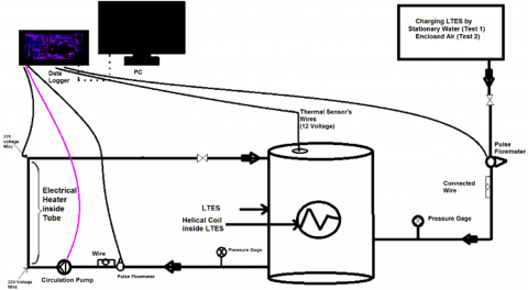
Figure 1 shows a schematic of the laboratory model.
The real model of laboratory system is shown in Figure 2 which indicates the experimental system for evaluating the performance of a thermal energy storage system. The system consists of a heat exchanger, data processing device, circulation pump, pressure relief valves, pulse flow meters 1 to 30 liters per minute, analog pressure gauges and Linear electrical heater as heat source. Distilled water is circulated through the coil by means of a pump, and light paraffin is embedded in cylinders inside the tank.
Thus, stagnant water (Test 1) or trapped air (Test 2) inside the tank is the heat transfer agent from the circulating-distilled water to the paraffinic material inside the cylinders.
Figure 1. Schematic of a laboratory model to perform the experiments
Figure 2. Latent Thermal Energy Storage System (TESS)
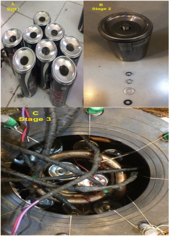
Figure 3. a) Injecting PCMs inside cylinders, b) Procedure of non-leakage packing for each cylinder, c) Insert the bottles in shell side of chamber to perform the test 1 and 2
Table 2. Specifications of phase change material (slack wax)
|
Properties |
PCM |
|
Thermal conductivity (liquid or solid) |
0.21 W/mK |
|
Density (liquid or solid) |
790 Kg/m3 |
|
Specific heat capacity (liquid or solid) |
2.15 KJ/kgK |
|
Latent heat of fusion |
180 KJ/kgK |
|
Melting Temperature |
47 oC |
|
Coefficient of volume expansion |
0.001 K-1 |
|
Thermal Diffusion Coefficient |
1.29⨯10-7 m2/s |
Dimension of each Aluminum cylinders which contains paraffin material are 0.26, 128, and 47 mm thick, high, and diameter, respectively. How to fill the cylinders, seal and embed them inside the heat exchanger is shown in Figure 3 stages a, b, and c. The capsules are located both inside and around the spiral coil (outside).
The electric heater is used as a heat source to control the temperature of the distilled water passing through the coil. The circulation pump is used to circulate the distilled water (in a closed cycle), and to adjust the flow rate (selective maximum or minimum mode of circulation of the fluid, by means of manual switches on the pump). manual valves are used to control the flow rate. The data processor reads 16 sensors (Ds18B20) digitally in the temperature range of -55 to +125℃. These sensors are capable of detecting the temperature of gas, liquid, or the simultaneous presence of gas and liquid with two percent accuracy. The sensors have a diameter of 1.841 mm, which were installed inside the metallic covers. The radial positions of the sensors in the horizontal planes can be adjusted with the help of suitable connections. The sensors are placed at different depths according to Table 1 in the tank (8 sensors at the inlet and 8 sensors at the outlet of circulating distilled water). The location of the sensors in these tests is on the side of the shell and in contact with the interface fluid inside the tank.
The data logger also has the ability to record the flow rates by pulses that indicate on display. A turbine pulse flowmeter is used to measure the flow rate with a measurement accuracy of 0.97% after calibration. The flowmeter is calibrated at different rates, taking into account the required times. In other words, the flow rate of the fluid flow can be calculated based on the pulse counter by recording the parameters in the data logger. Data storage has done for different parameters such as distilled water flow rate, different temperatures, time spent to completely melt the paraffin material.
Table 2 presents the thermos-physical characteristics of the paraffin material according to the manufacturer's data (Arash Mahya Paraffin Manufacturing Co., Tehran, Iran).
2.2 Physical model and procedures
Depending on the melting point of the paraffin materials used, in the range of 47 to 48℃, several tests have been designed based on different cycles of the circulation pump. The experiments of this study were performed at two flow rates for the pulsed values on the data logger equal to 47 and 90 pulses per minute. In other words, the mass flows used in this experiment, after calibrating the current-passing pulse-meter, were calculated to be 1 g/s for lower flow and 3.3 g/s for higher flow, respectively. Several tests have been performed on a laboratory model under controlled conditions, with a stationary water or trapped air fluids as a heat-transfer agents.
In Test 1, the inside of the TES is filled with water. This static water acts as an intermediate fluid to exchange heat between the circulating distilled water inside the spiral tube and the phase-change material inside the capsules. Rotating distilled water, over time, enters the system from the initial temperature of the charging process (approximately 20℃) to gain heat and increase temperature up to an average 60-80℃ which recall by sixteen sensors. In this case, the paraffin material melts inside the capsules by receiving the heat of distilled water through static water, and this process continues until the whole encapsulated material (recorded by sensors) is completely melted.
In Test 2, water is not added to the TES, and as a result the trapped air is responsible for heat exchange between the circulating distilled water inside the spiral tube and the phase change material inside the capsules. The whole space inside medium isolated by suitable sealant and caps to avoid any leakage of air to enter system for this test.
The location of the sensors in this test, as in the first test, is on the shell side and in contact with trapped air in the unit. It is expected that in this case, due to the presence of air as a heat exchanger, radiation play a pivotal role in the rate of heat exchange.
Based on the heat energy balance of the heat exchanger or any similar unit such as TES, it can be shown that the heat exchange between the circulating fluid (distilled water) and the phase change materials (paraffin) is as follows [14]:
$\dot{Q}=-\dot{m} c\left(T_{\text {out }}-T_{\text {in }}\right)$ (1)
$\dot{Q}=U A F \Delta T_{m l}$ (2)
$U=\frac{\dot{Q}}{A F \Delta T_{m l}}=\frac{\dot{m} c\left(T_{i n}-T_{o u t}\right)}{A F \Delta T_{m l}}$ (3)
The logarithmic mean temperature is obtained as follows [14]:
$\Delta T_{m l}=\frac{\left(T_{\text {out }}-T_{M \text { fin}}\quad \right)-\left(T_{\text {in }}-T_{\text {Mini }}\quad\right)}{\ln \left(\frac{T_{\text {out }}-T_{M \text { fin }}}{T_{\text {in }}-T_{\text {Mini }}} \quad \right)}$ (4)
In these equations, the temperatures $T_{\text {in }}, T_{\text {out }}, T_{\text {Mini }}$ and $T_{M f i n}$ represent the inlet and outlet temperatures of distilled water, respectively, and the initial and final temperatures of the paraffinic material inside the unit. It is noted that, correction factor for this kind of heat exchanger is considered as F parameter.
According to the given explanations, various experiments were performed in two stages of water-filled system and trapped air system. The results of these experiments are shown in Figures 4-8. This section examines these results.
For the first experiment (static water), the changes of the bulk temperature inside the heat storage system with respect to a dimensionless time function (Fourier number, Fo=αt/w2) for two different rates of circulating distilled water, in the presence and absence of encapsulated material in the cylinders are compared in Figure 4 (by applying error bars). Fourier numbers describe as a function for charging and dis-charging time performance under different conditions, which can be obtained empirically under consideration of TESS technology.
It is noted that, at any time due to nan-stable condition, mechanism of heat transferring process cannot be separated individually in each test. The bulk fluid temperature at different depth inside the TESS was gradually increased. The bulk temperature of static water in the system is obtained from the average temperature shown by 16 sensors in the system recorded by data logger.
As seen from Figure 4, the temperature profile of the static water fluid per 1 g/s distilled water flow rate is lower than that of the 3.3 g/s flow rate. Under the presence of encapsulated material, at about 0.7 to 2.6℃, differences in the curves of Figure 4 can be seen. While this temperature difference is about 5 degrees Celsius in comparison with the absence of encapsulated materials per flow of 3.3 g/s of circulating fluid. After the process begins, the paraffin material starts to melt from the body of the cylinders containing the phasing material and then penetrates into the cylinders. Over time and in the final stages of the melting process, stratified thermal layers occur inside the TES, and especially at higher points inside the unit, which first surround the cylinders and then all the upper surfaces of the chamber. At the beginning of the process, the conduction heat transfer played a role in the cylinder wall as the main parameter. This heat transfer mechanism continues until the viscous force overcomes the fluid motion. Over time, the buoyancy force takes on greater values and overcomes the viscous force and then convection heat transfer dominate in the melting process.
Therefore, the distribution of difference between the surface and bulk temperatures for the vertical cylinders in an assembly by unstable heat flux of electrical heater reach out convection mechanism to transfer to the top of the cylinders containing paraffin material and subsequently to higher levels inside the system. This variation in surface temperature along the cylinders is mainly due to the development of thermal boundary layer. During the melting process of test, thermal boundary layer gradually develops along the heated length resulting an increase in the surface temperatures along the cylinders. This temperature curve should increase up to the top of cylinders. However, this behavior was not observed in these experiments. Also, the physical properties of stationary water changes with the temperature change. The decrease in viscosity offers less resistance to flow of heat. The heat flow faces less resistance due to the increase in heat transferring by conduction and natural convection.
Figure 4. Bulk temperature changes of stationary water per Fo number for different rates of distilled water circulation fluid (test 1)
Figure 5. Bulk temperature changes of Enclosed Air per Fo numbers for different rates of distilled water circulation fluid (test 2)
In Figure 5 for the second experiment, the mean temperature changes of the air trapped inside the heat storage system relative to a dimensionless time function (Fourier number, Fo=αt/w2) for two different rates of circulating distilled water is shown (by applying error bars). Also, the effect of presence and absence of encapsulated materials in the cylinders are provided.
Under conditions of the presence of encapsulated material, at about 4.3 to 11.5℃, differences in the curves of Figure 5 can be seen. However, this temperature difference is about 10 to 35 degrees Celsius in comparison with the absence of encapsulated materials per flow of 3.3 g/s of circulating fluid. Contrary to Figure 4, over time, the dominant heat exchange mechanism is not only through convection current, but also radiative heat transfer. Thus, while charging the system through trapped air (in the presence or absence of paraffin material), improves system performance is observed. The significant variation in the curve of the temperature changes of the system is a decisive reason for the effectiveness of the radiation mechanism.
Figure 6. Comparison of Bulk temperature changes (average of 16 thermal sensors inside TES), for the maximum rate of circulating distilled water for tests 1 and 2
For better comparison between operating fluids (static water in the first experiment and trapped air in the second experiment), the average temperature of the fluid inside the storage system in terms of dimensionless time function (Fourier number Fo=αt/w2) for a distilled water flow of 3.3 g/s, in the presence and absence Paraffin materials are shown in Figure 6.
As shown in Figure 6, after 25 minutes, with the help of enclosed air (Test 2) and the presence of paraffin material, the system reached a temperature of 50℃, which is the melting range of paraffin materials. At the same time, the average temperature of the system has finally risen to 30℃ with the static water (Test 1). It is noted that, in the absence of paraffinic materials, this difference can be seen in the curves of the fluid operating static air and static water. This difference indicates the significant effect of the radiant heat transfer parameter in the heat transfer process to paraffinic materials inside the cylinders through the trapped air-trapped fluid. According to Figure 6, despite strengthening the natural convection mechanism in the first experiment, the upward trend of the temperature profile did not reach the profiles of the second experiment, which shows the dominant effect of the radiant parameter in the second experiment over the natural convection parameter in the first experiment.
On the other word, this phenomena can be explained that, in the case of natural heat transfer, a comparison between static water and trapped air can be made on the basis of the Grashof number(Gr). Assuming that in the first and second experiments, the temperature of the circulating distilled water at the inlet to the TES is approximately equal, then if the compressibility coefficient b and the kinetic viscosity u are calculated at an average of 35℃ for the air and water, the water Grashof number is fifty times more than of air. This means that heat transfer is a stronger by natural convection in water than in air. Therefore, due to the low thermal conductivity of air compared to water and also the weaker heat transferring of air movement, the main heat transferring between the cylinders and the inner wall of the TESS will be through radiation in the trapped air state.
Figure 7 shows the temporal variations of the total heat transfer coefficient in different circulating distilled water rates for TES with the phase change material, resulting from the melting process under experimental conditions, for the static fluid (first experiment). In these diagrams, heterogeneous fluctuations are observed, especially at lower flow rates of the circulation fluid, which may be due to the non-uniform melting process of paraffinic materials in the cylinders.
The results obtained in Figure 7 show a 3 to 5-fold increase in the total heat transfer coefficient for the maximum flow rate relative to the minimum flow rate in this experiment. In general, increasing the flow rate of the circulating fluid increases the Reynolds number and consequently the growth of the Nusselt number(Nu) and result in the higher transfer heat transfer coefficient. Therefore, these parameters have a direct effect on the overall heat transfer coefficient.
Figure 7. Evaluation of total heat transfer coefficient values for different flow rates of distilled water inside the coil during the melting process in terms of time for the test 1 (stationary water)
Figure 8. Comparison of total heat transfer coefficient values for maximum circulating distilled water rate inside coil during the melting process over time for both tests (1 and 2)
In Figure 8, the temporal variations of the total heat transfer coefficient at the maximum flow rate of circulating distilled water for TES with the paraffin are compared in the first and second experiments.
Figure 8 shows that the heat exchange is greater when using trapped air medium than stationary water fluid. After 25 minutes from the start of the storage process, the overall heat transfer coefficient increased up to 3 times in the enclosing air test. The reason for this is due to the significant effect of radiation heat transfer mechanism in this case.
Uncertainties in this study are approximately 0.1℃ for temperature, + 0.05 watt for electric heaters using an electric power meter, and +2% for temperature. These errors are assumed to be negligible in the results obtained in this study. Heat transfer parameters were continuously measured to ensure experimental data. As can be seen from the test system, the manufacturer's unique thermal insulation has been used to reduce heat loss to the surroundings.
On the other hand, by using the Klein and McClintock uncertainty analysis method [15], the distribution of uncertainties in the experimental results shows the effect of uncertainties on independent variables. Using this method, by defining the independent variables $x_{1}, x_{2}, \ldots, x_{n}$, the uncertainty of the U parameter is determined for independent parameters in the form of the U ( xi ) function as follows:
$M=f\left(x_{1}, x_{2}, \ldots, x_{n}\right)$ (5)
$U(M)=\sqrt{\sum_{i=1}^{n}\left(\frac{\partial f}{\partial x} U\left(x_{i}\right)\right)^{2}}$ (6)
This method was used to estimate the uncertainties in the experimental results. Uncertainty values in measuring thermal properties including heat capacity of solid and liquid phases and latent heat of melting were 5.1%, 4.8%, and 2.1%, respectively. In addition to the above values, the most uncertainties for the overall heat transfer coefficient and thermal diffusion numbers were 1.8% and 6.5%, respectively.
In this study, the melting process of encapsulated materials in a thermal energy storage system in the form of a helical shell-tube unit have been investigated. The unsteady-state mixed heat transfer inside an individual TESS by use of intermediate fluids (stationary water and trapped air) were tested experimentally. The effect of combined heat transfer (conduction, convection, and radiation) in an assembly of thirteen cylinders containing phase change materials during charging process under different conditions was investigated.
The comparison of Bulk temperature changes versus the Fo number at various values of heat flux, for different rates of circulating distilled water are presented in this study. The experimental results indicated the bulk fluids temperature along the vertical cylinders increased axially up to top of system mainly at trapped air test due to development of thermal boundary layer. Fo numbers through trapped air are one-third of the values associated with static water which indicate acceleration of heat transferring in air trapped test. The study is ranged of Fourier numbers (0 < FO < 1) as a dimensionless parameter. The upward trend of the temperature profiles and the overall heat transfer coefficient of the system in the trapped air test was curvilinear, while in the static water test, it is relatively linear. These curved changes in the ascending trend of the system temperature by use of trapped air indicate the effect of radiative heat transfer and the dependence of the radiant heat transfer rate on the fourth order of temperature of the internal surfaces of the system with high emission and absorption coefficients. Also, the effect of distilled water circulation flow parameters on the charging process was evaluated through various temperature and flow rate tests which indicate that higher flow rate of circulation distilled water doesn't have significant effect in rising bulk temperature of experimental tests and the effect of circulating distilled water temperature on the system charging process is more significant than its flow rates. One of the general results of this study was the higher performance of system which has been achieved by use of trapped air test, that occurred under individual laboratory conditions.
Therefore, by manipulating system to store heat energy mostly in radiation mechanism, with the help of stainless-steel capsules as a Macro Encapsulation Phase Change Material, experimental model can be commercialize to integrate with solar collector in the reachable temperature range of 20 to 50℃ for the heat storage system in an alternative equipment such as Heating and Ventilation Air Conditioning (HVAC) systems.
This work is financially supported by the Shahrekord University, Iran.
|
A |
Area of heat Area of heat transferring(m2) |
|
C |
specific heat at c specific heat at constant pressure (kJ/kg K) |
|
F |
Correction c Correction coefficient (deviation in the heat exchanger) |
|
Fo |
Fourier num Fourier number |
|
HTF |
Heat Transfer Heat Transfer Fluid |
|
LTES |
Latent Thermal Latent Thermal Energy Storage |
|
MEPCM |
Macro- Macro-n Macro Encapsulation Phase Change Material |
|
m |
Kilo gram(kg) |
|
M |
As a function for Variables x |
|
PCM |
Phase Change Material |
|
P |
Pressure(kg.m-1s-2) |
|
Q |
heat transfer rate (w) |
|
t |
Time(s) |
|
T |
Temperature(℃) |
|
u |
Velocity(m.s-1) |
|
U |
Total Heat Tranfer Coefficient (w/m2.k) |
|
U(M) |
Uncertainty Parameters |
|
W |
Internal Diameter of Unit(m) |
|
Greek symbol |
|
|
ρ |
Density (Kg/m3) |
|
∆ |
Difference |
|
α |
Thermal diffusity(m2.s) |
|
Subscripts |
|
|
fin |
Final |
|
ini |
initial |
|
M |
Material |
|
out |
outlet |
|
in |
inlet |
|
Sur |
Surrounding |
|
conv |
Convection |
|
rad |
radiation |
|
S |
Surface |
|
∞ |
source |
|
w |
Stationary water |
|
A |
Enclosed air |
[1] Akeiber, H., Nejat, P., Majid, M.Z.A., et al. (2016). A review on phase change material (PCM) for sustainable passive cooling in building envelopes. Renewable and Sustainable Energy Reviews, 60: 1470-1497. https://doi.org/10.1016/j.rser.2016.03.036
[2] Sarbu, I., Sebarchievici, C. (2018). A comprehensive review of thermal energy storage. Sustainability, 10(1): 191. https://doi.org/10.3390/su10010191
[3] Alva, G., Liu, L., Huang, X., Fang, G. (2017). Thermal energy storage materials and systems for solar energy applications. Renewable and Sustainable Energy Reviews, 68: 693-706. https://doi.org/10.1016/j.rser.2016.10.021
[4] Liu, C., Groulx, D. (2014). Experimental study of the phase change heat transfer inside a horizontal cylindrical latent heat energy storage system. International Journal of Thermal Sciences, 82: 100-110. https://doi.org/10.1016/j.ijthermalsci.2014.03.014
[5] Murray, R.E., Groulx, D. (2014). Experimental study of the phase change and energy characteristics inside a cylindrical latent heat energy storage system: Part 1 consecutive charging and discharging. Renewable Energy, 62: 571-581. https://doi.org/10.1016/j.renene.2013.08.007
[6] Sciacovelli, A., Gagliardi, F., Verda, V. (2015). Maximization of performance of a PCM latent heat storage system with innovative fins. Applied Energy, 137: 707-715. https://doi.org/10.1016/j.apenergy.2014.07.015
[7] Jesumathy, S.P., Udayakumar, M., Suresh, S., Jegadheeswaran, S. (2014). An experimental study on heat transfer characteristics of paraffin wax in horizontal double pipe heat latent heat storage unit. Journal of the Taiwan Institute of Chemical Engineers, 45(4): 1298-1306. https://doi.org/10.1016/j.jtice.2014.03.007
[8] Rahimi, M., Ranjbar, A.A., Ganji, D.D., Sedighi, K., Hosseini, M.J., Bahrampoury, R. (2014). Analysis of geometrical and operational parameters of PCM in a fin and tube heat exchanger. International Communications in Heat and Mass Transfer, 53: 109-115. https://doi.org/10.1016/j.icheatmasstransfer.2014.02.025
[9] Han, X., Li, Y., Yuan, L., Wang, Q., Zhang, H., Lian, H., Zhang, G., Xiao, L. (2017). Experimental study on effect of microencapsulated phase change coating on indoor temperature response and energy consumption. Advances in Mechanical Engineering, 9(6): 1687814017703901. https://doi.org/10.1177%2F1687814017703901
[10] Wu, S.M., Fang, G.Y., Liu, X. (2010). Dynamic charging performance of a solar latent heat storage unit for efficient energy utilization. Chemical Engineering & Technology: Industrial Chemistry-Plant Equipment-Process Engineering-Biotechnology, 33(3): 455-460. https://doi.org/10.1002/ceat.200900257
[11] Zhou, Z., Zhang, Z., Zuo, J., Huang, K., Zhang, L. (2015). Phase change materials for solar thermal energy storage in residential buildings in cold climate. Renewable and Sustainable Energy Reviews, 48: 692-703. https://doi.org/10.1016/j.rser.2015.04.048
[12] Raul, A., Jain, M., Gaikwad, S., Saha, S.K. (2018). Modelling and experimental study of latent heat thermal energy storage with encapsulated PCMs for solar thermal applications. Applied Thermal Engineering, 143: 415-428. https://doi.org/10.1016/j.applthermaleng.2018.07.123
[13] Höhlein, S., König-Haagen, A., Brüggemann, D. (2018). Macro-encapsulation of inorganic phase-change materials (PCM) in metal capsules. Materials, 11(9): 1752. https://doi.org/10.3390/ma11091752
[14] Levenspiel, O. (2014). Engineering Flow and Heat Exchange. Springer.
[15] Kline, S.J. (1953). Describing uncertainty in single sample experiments. Mech. Engineering, 75: 3-8.