Harto Tanujaya* | Steven Darmawan
© 2021 IIETA. This article is published by IIETA and is licensed under the CC BY 4.0 license (http://creativecommons.org/licenses/by/4.0/).
OPEN ACCESS
Heat exchanger is usually used in manufacturing process. At present, many researchers have efforts to increase the performance of the heat exchanger with less of the cost. This research discussed about the performance of heat exchanger using 40% cut segmental baffles compared with modified double segmental baffles disc-and-doughnut type. In this study, the investigation of the computational results consisted of heat flux, velocity profile along the heat exchanger, pressure distribution and, theoretical heat transfer coefficient and heat exchanger effectiveness. The model was calculated using finite difference method forward modeling with Multiphysics Software and focuses on the performance evaluation of the small shell-and-tube heat exchanger (STHE) – laboratory type. The tubes are composed of 14 tubes with 0.583 m length, triangular 30° rotated pitch. The pipe radius of shell and tube are 0.055 m and 0.00635 m, respectively. The baffle radius of disc and doughnut are 0.055 m and 0.025 m, respectively, and the baffle radius of 40% cut segmental baffles are 0.055 m. Both types of the baffle have a distance of 0.116 m which is evenly distributed along the shell. The generalized minimal residual (GMRES) method for the fluid flow case used as an iterative method for solving some of the complex linear equations shows good performance as in reliability and validity. For the 40% cut segmental baffles, fluid flow makes a zigzag pattern, an Eddy or swirling of a fluid, and there was some back mixing of fluid stream which caused several dead zones along the shell. The occurrence of the dead zones caused the heat transfer to be ineffective and gave lower value compared to the double segmental disc-and-doughnut baffles. The 40% cut segmental baffles was also seen to have a higher pressure at the outlet region than the double segmental disc-and-doughnut baffles. The disc-and-doughnut baffles leads to a turbulent fluid flow which causes an increase in heat transfer characteristics and also lower pressure drop than the 40% cut segmental baffles. Based on the theoretical, both types of disc-and-doughnut baffles and the 40% cut segmental baffles of heat exchanger investigated have highest effectiveness at the lowest mass flow rate of the hot fluids (tube).
heat exchanger, STHE, segmental baffles, disc-and-doughnut, effectiveness
Heat exchanger is useful in industry, especially to support the production and manufacturing process. Heat transfer theory is used to calculate and investigated the process. At present, many researchers have efforts to increase the performance and effectiveness of the heat exchanger with less of the cost. Performance and effectiveness of heat exchanger are measured through the difference of temperature of two fluids and the physical design of the heat exchanger. The effectiveness is also determined by calculating the overall heat transfer coefficient.
Many researchers usually use the prototypes to do the experiment and theoretical investigation of heat transfer of the heat exchanger. Lorenzini, et al. [1, 2] investigate and analyze the heat transfer of 128 horizontal tubes of a crossflow air-cooled heat exchanger with aluminum fins, and also make an experiment about convective heat transfer in a fully developed turbulent flow of water in a horizontal pipe at uniform wall heat flux. D’Agostino et al. [3, 4] evaluate the energy performances of the employment of an Earth-to-Air-Heat Exchanger positioned in the upstream of the air-handling unit of an air conditioning system for an office building in Naples (South Italy), and also investigate the energy performances of Heating, Ventilation and Air Conditioning system coupled with a horizontal-pipes Ground-to-Air Heat Exchanger at Rio de Janeiro, Dubai, Naples, Ottawa. Kumar and Singh [5] discuss about the hydraulic performance of chevron type plate heat exchanger for different aspect ratios using water as the working fluid in the channels. The flow distribution and pressure drop in the U-type arrangement plate heat exchangers are studied for a wide range of Reynolds number (200-5800).
At present, researchers use the simulation to develop and reduce the unnecessary time to increase the effectiveness of the heat exchanger. Missirlis et al. [6] investigate the thermal and flow field of a heat exchanger designed for aero engine applications. The investigation is performed with the combined use of experimental measurements and CFD computations, with the geometry of the heat exchanger modeled and computed using the Shear Stress Transport turbulence model. Ozden and Tari [7] observed the shell side of the shell-and-tube heat exchanger using numerical modelling in a small heat exchanger. Vukic et al. [8] also discussed about the effectiveness of shell-and-tube heat exchanger using different variation number of segmental baffle.
This research investigates the shell-and-tube heat exchanger (STHE) with disc-and-doughnut baffles type and 40% cut segmental baffles. The performance and effectiveness of the STHE were discussed numerically and theoretically. Experimental research has already been carried out by Tanujaya and Sukania [9], whom investigate the effectiveness of the prototype of shell-and-tube heat exchanger using stationary-head with ring rubber clamp, with single segmental baffle type. Numerically, the research was analyzed using Multiphysics solver and simulation software. This solver is a finite element analysis. It is usually use for engineering applications, various physics, and coupled phenomena / Multiphysics. These features are appropriate to combine the several process such as heat and momentum transfer that usually occurred in shell-and-tube heat exchanger. In this study, investigation of the computational results consisted of heat flux, profile velocity along the heat exchanger, pressure distribution, heat transfer coefficient and heat exchanger effectiveness.
2.1 Governing equations
The geometry is built by Multiphysics software’s drawing operations. Heat transfer theory was used to help investigate the heat transfer such as conduction, convection, thermal radiation and turbulent flow mechanism, also a combination of them or in collaboration with other physical properties [10]. This module can be applied using multiphysics coupling interface as temperature coupling between heat transfer and fluid flow interfaces is used in the computation.
The heat transfer was obtained from conservation law that complete the continuum mechanics theory; conservation of mass, conservation of linear momentum, and conservation of angular momentum [11, 12],
$\frac{\partial \rho}{\partial t} \nabla(\rho u)=0$ (1)
$\rho \frac{\partial u}{\partial t}+\rho(u \cdot \nabla) u=\nabla \cdot \sigma+F_{v}$ (2)
$\sigma^{T}=\sigma$ (3)
so, the localized heat balance equation in the spatial frame,
$\rho \frac{\partial E}{\partial t}+\rho u \cdot \nabla E+\nabla \cdot\left(q+q_{r}\right)=-(\sigma: D)+Q$ (4)
with $\sigma$ as the Cauchy stress tensor which are split into static and deviatoric parts,
$\sigma=-p I+\tau$ (5)
and the heat transfer in fluids interface are solved using,
$\rho C_{p}\left(\frac{\partial T}{\partial t}+u \cdot \nabla T\right)+\nabla \cdot\left(q+q_{r}\right)=\alpha_{p} T\left(\frac{\partial p}{\partial t}+u \cdot \nabla p\right)+\tau: \nabla u+Q$ (6)
where, ρ is the density (kg/m3), Cp is the specific heat capacity at constant pressure (J/(kg·K)), T is the absolute temperature (K), u is the velocity vector (m/s), q is the heat flux by conduction (W/m2), qr is the heat flux by radiation (W/m2), αp is the coefficient of thermal expansion (1/K),
$\alpha_{p}=-\frac{1}{\rho} \frac{\partial \rho}{\partial T}$ (7)
p is the pressure (Pa), τ is the viscous stress tensor (Pa), $\mathcal{Q}$ is the heat sources other than viscous dissipation (W/m3). In this case, the temperature does not change with time with a steady-state conditions.
Theoretically, the Nusselt number is suitable to calculate the heat transfer coefficient which is used to measure the energy of heat transfer in the system. There are two kinds of flow, inside the tube (hot fluid) and outside the tube – inside the shell (cold fluid). Inside the tube is calculated based on the result of Dittus-Boelter [13, 14] for internal flow, with n = 0.4 (shell) for heating and n=0.3 (tube) for cooling,
$N u_{t u b e}=0,023 R e_{D}^{4 / 5} \operatorname{Pr}^{n}$ (8)
While Nusselt number outside the tube or inside the shell is calculated by Churchill and Bernstein [15], this equation is used for large Reynolds number with value between 100 < Red < 10E7. The shell is composed of 14 tubes, with crossflow fluid.
$N u_{\text {shell }}=0.3+\frac{0.62 \cdot \operatorname{Re}^{1 / 2} \operatorname{Pr}^{1 / 3}}{\left[1+\left(\frac{0.4}{\operatorname{Pr}}\right)^{2 / 3} \quad \right]^{3 / 4}}\left[1+\left(\frac{R e}{282000}\right)^{5 / 8}\right]^{4 / 5}$ (9)
Reynolds number are investigated using the maximum velocity of the fluid inside the shell umax shell,
$R e_{\text {shell }}=\frac{\rho . u_{\text {max shell }} \quad . d_{\text {shell }}}{\mu_{\text {shell }}}$ (10)
with sn as the vertical distance between the tube so,
$u_{\text {max.shell }}=u_{\text {shell }}\left(\frac{s_{n}}{s_{n}-d_{t u b e}}\right)$ (11)
The total area of heat transfer is calculated using the amount of the tube multiplied by the curve surface area of the tube, so,
$A_{t u b e}=N . \pi . d_{t u b e} . l$ (12)
where, N is the amount of the tubes (14 tubes) and l is the length of the tubes. The convection heat transfer coefficient of shell (hshell) and the total heat transfer rate (q) may also be expressed theoretically,
$h_{\text {shell }}=\frac{N u_{\text {shell }} \cdot k_{f}}{d_{\text {shell }}}$ (13)
$q=h_{\text {shell }} A_{\text {tube }} \Delta T$ (14)
where, kf is the conductivity of the fluid in the bulk temperature and $\Delta$T is the difference temperature of the both fluids. The effectiveness of the heat exchanger is a function of NTU (Number Thermal Unit) and the ratio of the minimum to the maximum value of heat capacity rate for hot and cold fluids (Cmin/Cmax).
$\varepsilon=\boldsymbol{f}\left(\boldsymbol{N T U}, \frac{\boldsymbol{C}_{\min }}{\boldsymbol{C}_{\max }}\right)$ (15)
2.2 Simulation setup
In this research, both water flow inside the tubes and outside the tubes (within the shell of the heat exchanger) are used. Both of the fluids have different inlet temperatures when entering the tubes and the shell. Hot water enters the tube side with velocity of 1, 3, 5, 10 m/s and temperature of 373.15 K. Cold water enters the shell side with velocity of 1, 3, 5, 10 m/s and temperature of 278.15 K. At both inlets, the value of turbulence length scale of 4.445 × 10⁻⁴ m.
The radius of the shell and the tube are 0.055 m and 0.00635 m, respectively. The tubes are composed of 14 tubes with 0.583 m length, triangular 30° rotated pitch. First, the baffles of disc-and-doughnut model, with radius of disc-and-doughnut of 0.055 m and 0.025 m, respectively. Second, the radius of 40% cut segmental baffles are 0.055 m. Both types, the distance between baffles of 0.116 m is evenly distributed along the shell. The total length of heat exchanger is 0.743 m. The inlet and outlet radius of both shell and tube are 0.025 m. Counter flow is used in the simulation. The outlet, both shell and tube are set on the normal flow with suppressed backflow.
The space dimension of the geometry was pictured using 3D axisymmetric with heat transfer and k - e turbulent flow of the physics problem. Stationary analyses were used for computation steps in this study. The material properties used were water and water, with Aluminum (Al) as the material of the baffles. The material properties of heat capacity at constant pressure, thermal conductivity, density, Young modulus, and ratio of specific heats are taken from an internal material database of both water and Aluminum as shown in Table 1.
Table 1. Material properties
|
Property |
Value |
Unit |
|
Aluminum (Al);
Water;
|
900 238 2700 70E9
Cp(T[1/K]) k(T[1/K]) 1000 1.0 |
J/(kg.K) W/(m.K) Kg/m3 Pa
J/(kg.K) W/(m.K) Kg/m3 1 |
Notes: The heat capacity at constant pressure and thermal conductivity for water is a polynomial function of the temperature.
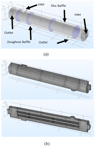
Figure 1 shows the position of the baffles and inlet - outlet of the shell and the tube, respectively. The geometry mesh is also shown in the figure. The sequence type of mesh has to be created using user-controlled mesh with element size of extremely-coarse and finer meshes to make accurate solutions that are calculated using numerical techniques. The extremely-coarse element size meshes are distributed along the volume of the shell and stationary-head. The finer meshes are distributed along the tubes and even finer close to sharp edges at the cross section of the baffles with tubes and corners. The free tetrahedral complete mesh consists of 294788 domain elements, 30682 boundary elements, and 4205 edge elements, with minimum and maximum element size of 3.78 × 10⁻⁴ m and 0.0035 m, respectively. Temperature, velocity, and pressure distribution are analyzed using COMSOL 5.2a. The calculation was solved using notebook with Intel® CoreTM i7 Processors, 10th Generation, 4.50 GHz, 16 GB of RAM. The total calculations time of 32 variations study case need 39 hours.
Figure 1. Design of shell-and-tube disc-and-doughnut baffles (a) parts of shell-and-tube, (b) meshing symmetry
2.3 Profile
Heat transfer along the flow distribution can be shown and understood with the velocity and temperature profiles. Both of the profiles are drawn across the cross section along the length of shell-and-tube which are divided in 5 parts/lines and 5 points as shown in Figure 2, namely A 1–5, B 1–5, C 1-5, D 1-5, and E 1-5. These zones/positions are drawn to understand both the velocity and temperature profiles along the heat exchanger.
Figure 2. Profile position of the points along of shell-and-tube and cross-section
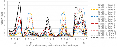
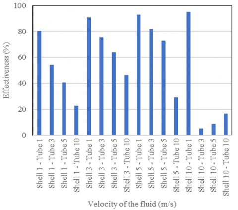
The velocity of water (inlet) in shell side are 1, 3, 5, 10 m/s and tube side are 1, 3, 5, 10 m/s. To simplify, they are grouped and named with first and second numbers. The first numbers are the velocity of water entering the shell inlet, and second numbers are velocity of water entering the tube inlet. The legends used in Figure 9 and Figure 10 are Shell 1-Tube 1, Shell 1-Tube 3, Shell 1- Tube 5, Shell 1- Tube 10, Shell 3- Tube 1, Shell 3- Tube 3, Shell 3- Tube 5, Shell 3- Tube 10, Shell 5- Tube 1, Shell 5- Tube 3, Shell 5- Tube 5, Shell 5- Tube 10, Shell 10- Tube 1, Shell 10- Tube 3, Shell 10- Tube 5, and Shell 10- Tube 10.
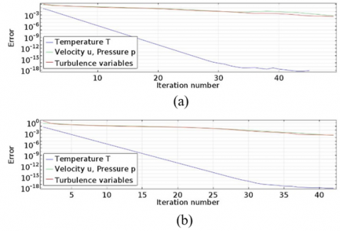
The accuracy, reliability and validity of the results are important when solving a finite element model. Figure 3 shows the convergence plot of calculation which give the required accuracy value of the heat transfer rate. Plotting of the residual in momentum equations, the velocity field, pressure, and turbulence variables. The segregated solvers are used to solve the governing equations separately.
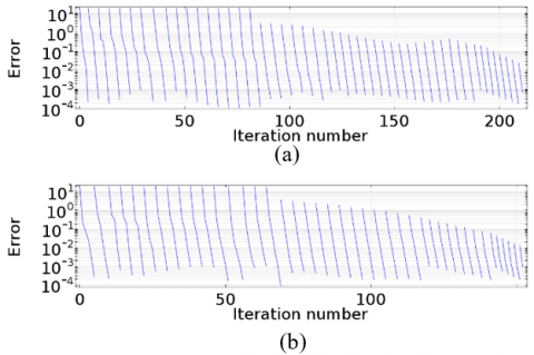
Figure 4 shows the generalized minimal residual (GMRES) method for the fluid flow case. This method is an iterative method for solving some of the complex linear equations with good performance in reliability and validity.
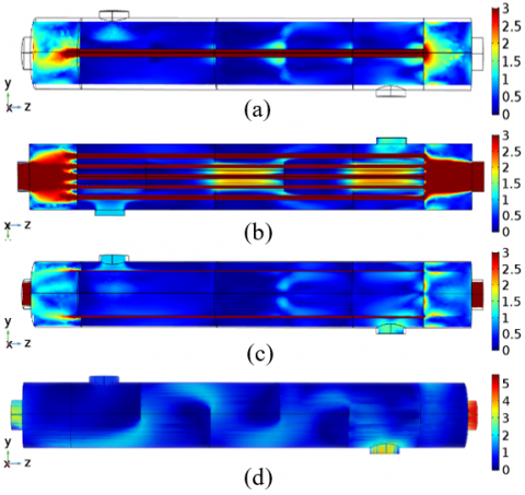
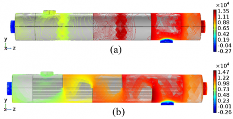
One of the important factors which influence the fluid flow is the baffle types. Figure 5 show the velocity magnitude inside the shell for disc-and-doughnut baffles and the 40% cut segmental baffles. Heat transfer increases with velocity and direct fluid stream. The fluid flow depends on the types and orientation of the baffles. The Figure 5(a) and (b) show the one slice and 5 slices at the inside center of the heat exchanger, respectively, and 5(c) show the five slices from the external wall of disc-and-doughnut baffles of heat exchanger. For double segmental disc-and-doughnut baffles, the fluid flows are observed to have higher velocity around the disc with less dead zone. For the 40% cut segmental baffles, fluid flow makes a zigzag pattern, an Eddy or swirling of a fluid, and there is some back mixing of fluid stream which cause several dead zones along the shell. The many occurrence of dead zones caused the heat transfer to be ineffective and has a lower value than double segmental disc-and-doughnut baffles.
Figure 6 shows the temperature distribution inside the shell of both the double segmental disc-and-doughnut baffles and 40% cut segmental baffles. Based on both of the simulations, it can be noticed that the double segmental is seen to be more efficient and have a better result for heat transfer as shown in the distribution of temperature along the shell.
Figure 3. Convergence plot, (a) disc-and-doughnut baffles, (b) 40% cut segmental baffles
Figure 4. GMRES, (a) disc-and-doughnut baffles, (b) 40% cut segmental baffles
Figure 5. Velocity magnitude contours (m/s), (a) cross section 1 slice, (b) cross section 5 slices, (c) external wall of disc-and-doughnut baffles, (d) 40% cut segmental baffles
Figure 6. Temperature contours (K), (a) disc-and-doughnut baffles, (b) 40% cut segmental baffles
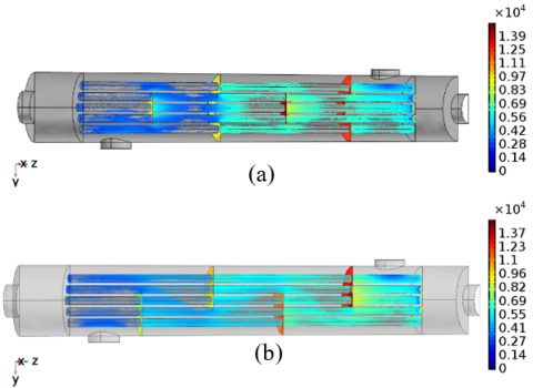
Figure 7. Pressure contours – shell surface (Pa), (a) disc-and-doughnut baffles, (b) 40% cut segmental baffles
Figure 8. Pressure contours - tube surface (Pa), (a) disc-and-doughnut baffles, (b) 40% cut segmental baffles
Figures 7 and 8 show the pressure distribution inside the shell, and the pressure contours on the tube surface, respectively, of both the double segmental disc-and-doughnut baffles and 40% cut segmental baffles. The pressure drop is one of important value in the shell-and-tube heat exchanger as it determined and is related to the efficiency and power consumption, which are used to calculate the operating cost of the system. Based on both figures, the 40% cut segmental baffles is seen to have a higher pressure at the inlet and outlet regions than the double segmental disc-and-doughnut baffles. Inside the shell of the double segmental disc-and-doughnut baffles is shown to have several regions with lesser pressure, while the higher pressure regions were detected only around the disc-and-doughnut baffles.
Figures 9 and 10 show the velocity distribution of disc-and-doughnut and 40% cut segmental baffles, respectively, based on the point position profile shown in Figure 2. Both of the figures at graph A (inlet side) and E (outlet side) showed that the fluid velocity distribution gave bigger value than the others (graph B, C, D). The Graph A of disc-and-doughnut baffles shows that the velocity increases corresponding to the point profile towards the bottom of the inlet side. However, the velocity of the 40% cut segmental baffles has the biggest value near the inlet side. The velocity profiles of graph A of disc-and-doughnut baffles for shell 1 – tube 1 to 10 of 0.912 to 1.016 m/s, shell 3 - tube 1 to 10 of 2.586 to 2.595 m/s, shell 5 – tube 1 to 10 of 4.631 to 4.779 m/s, shell 10 – tube 1 to 10 of 8.481 to 8.518 m/s. The Graph E of disc-and-doughnut baffles indicates that the fluid velocity distribution at the outlet side of point profile 1 to 5 are almost on the average value. The graph E of 40% cut segmental baffles for shell 1 – tube 1 to 10 of 0.906 to 5.156 m/s, shell 3 – tube 1 to 10 of 1.489 to 5.987 m/s, shell 5 – tube 1 to 10 of 1.956 to 5.886 m/s, shell 1 – tube 1 to 10 of 3.086 to 7.483 m/s. The fluid velocity distribution of both figures on graph of B, C, D show that the graph of disc-and-doughnut baffles have higher velocity than the graph of 40% cut segmental baffles.
Figure 9. Velocity distribution of disc-and-doughnut based on position profile
Figure 10. Velocity distribution of 40% cut segmental baffles based on position profile
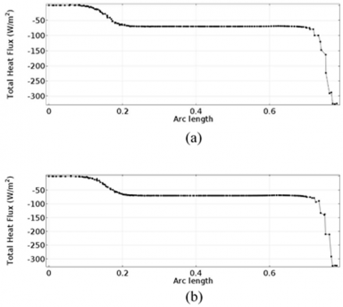
The heat flux measurements are used for many reasons, one of them is to increase the safety of the systems and save energy. Figures 11 and 12 show the total heat flux with temperature difference passing along heat exchanger from the inlet side to the outlet side with the flow of direction opposite to the normal vector direction. Both figures show that the heat flux have significantly change increased when the fluid flowing in and out through the inlet and outlet side, respectively. Total heat flux of disc-and-doughnut baffles investigated have better results than the 40% cut segmental baffles, one. This indicates that the disc-and-doughnut baffles have good results in heat transfer.
Figure 11. Total heat flux with temperatures difference, (a) disc-and-doughnut baffles, (b) 40% cut segmental baffles
Figure 12. Total heat flux along heat exchanger, (a) disc-and-doughnut baffles, (b) 40% cut segmental baffles
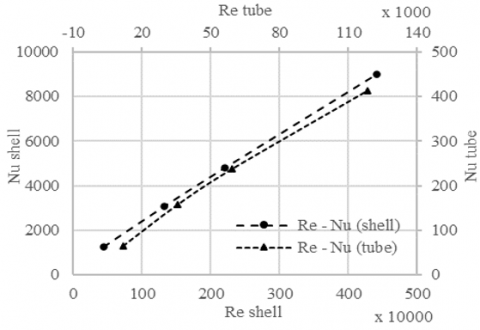
Figures 13 to 15 are the graphs correlated to Eq. (8) and (15). Figure 13 shows the relationship of the Reynolds number with Nusselt number. The Reynolds number of both the shell and tube have turbulence fluids phenomena, which are shown with the Reynolds number value. The Nusselt number is one of the important numbers to evaluate the effectiveness of the heat exchanger and is also correlated to the convective heat transfer coefficient, characteristic length of the shell/tube and thermal conductivity of the materials that are used. It was observed that the both Nusselt number of the shell-side (cold fluid) and tube-side (hot fluid) increase, as both the Reynolds number of the shell-side and tube-side increases. This indicates that the trend phenomena of the results are in accordance with the theory, which are the Nusselt number directly proportional with Reynolds number [9]. These results also indicate that the theoretical calculation have the same phenomena with the simulation.
Figure 13. Relationship of Reynolds and Nusselt Number of heat exchanger
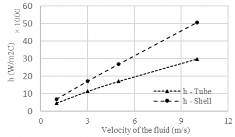
Figure 14. Heat transfer coefficient of shell and tube side of heat exchanger
Figure 15. Effectiveness of the heat exchanger
Figure 14 shows the relationship of convective heat transfer coefficient and velocity of the fluids. Generally, the graphs show that the value of convective heat transfer coefficient (h) for both hot and cold fluids in the shell and tube, respectively increase proportional to the velocity of fluids increases.
Figure 15 shows the relationship between effectiveness (e) of the heat exchanger versus velocity of the fluid. The trend of graphs shows the effectiveness decreases as the velocity of the hot fluids (tube) increases at each same velocity of the cold fluids (shell). It indicates that the effectiveness was influenced by the amount and variations of velocity and mass flow rates inside the shell and the tube.
In this research, numerical and theoretical simulation for heat exchanger with different type of baffles and variation of mass flow rates are performed to reveal the effect of different type of baffles on heat transfer and pressure drop characteristics. The baffle type of disc-and-doughnut baffles leads to turbulence of the fluid flow which causes increase in heat transfer characteristics and also have lower pressure drop than the 40% cut segmental baffles. Based on the theoretically, both type of disc-and-doughnut baffles and the 40% cut segmental baffles of heat exchanger that are investigated have the highest effectiveness at the lowest mass flow rate of the hot fluids (tube).
This work is supported and funded by Institute of Research and Community Engagement (LPPM) Universitas Tarumanagara, Indonesia. The authors wish to thank all of the participating personnel for their help, support and suggestions.
|
$\sigma$ |
Cauchy stress tensor |
|
Cp |
specific heat capacity at constant pressure [J/(kg·K)] |
|
T |
Temperature |
|
u |
Velocity vector [m/s] |
|
q |
Heat flux by conduction [W/m2] |
|
qr |
Heat flux by radiation [W/m2] |
|
αp |
Coefficient of thermal expansion [1/K] |
|
p |
Pressure [Pa] |
|
τ |
Viscous stress tensor [Pa] |
|
$\mathcal{Q}$ |
Heat sources other than viscous dissipation [W/m3] |
|
Nutube |
Nusselt Number of tube |
|
Nushell |
Nusselt Number of shell |
|
ReD |
Reynolds number |
|
Reshell |
Reynolds number of shell |
|
Pr |
Prandtl number |
|
umax shell |
Maximum velocity of the fluid inside the shell [m/s] |
|
ushell |
Velocity of the fluid inside the shell [m/s] |
|
dshell |
Diameter of shell [m] |
|
dtube |
Diameter of tube [m] |
|
hshell
|
Convection heat transfer coefficient of shell [W/m2C] |
|
kf |
Conductivity of the fluid [W/mC] |
|
q |
Total heat transfer rate [W] |
|
$\Delta$T |
Difference temperature of the both fluids [C] |
|
$\varepsilon$ |
Effectiveness |
|
NTU |
Number Transfer Unit |
|
Cmin |
Minimum heat capacity rate |
|
Cmax |
Maximum heat capacity rate |
|
$\rho$ |
Density [kg/m3] |
|
µshell |
Viscosity dynamic [kg/m s] |
|
sn |
Distance between the tube vertically [m] |
|
Atube |
Total area of the tube [m2] |
|
N |
Amount of the tubes |
|
l |
Length of tubes [m] |
[1] Lorenzini, E., Orlandelli, C., Spiga, M., Tartarini, P. (1993). Experimental investigation of a crossflow heat exchanger. Exp. Therm. Fluid Sci., 7(2): 131. https://doi.org/10.1016/0894-1777(93)90121-X
[2] Lorenzini, E., Orlandelli, C., Spiga, M. (1982). Experimental investigation of heat transfer for turbulent flow in a circular pipe. Termotec. Milano, 36: 55-59..
[3] D’Agostino, D., Esposito, F., Greco, A., Masselli, C., Minichiello, F. (2020). Parametric analysis on an earth-to-air heat exchanger employed in an air conditioning system. Energies, 13(11): 2925. https://doi.org/10.3390/en13112925
[4] D’Agostino, D., Esposito, F., Greco, A., Masselli, C., Minichiello, F. (2020). The energy performances of a ground-to-air heat exchanger: A comparison among köppen climatic areas. Energies, 13(11): 2895. https://doi.org/10.3390/en13112895
[5] Kumar, B., Singh, S.N. (2015). Analytical studies on the hydraulic performance of chevron type plate heat exchanger. International Journal of Heat and Technology, 33(1): 17-24. https://doi.org/10.18280/ijht.330103
[6] Missirlis, D., Flouros, M., Yakinthos, K. (2011). Heat transfer and flow field investigation of a heat exchanger for aero engine applications. Int. J. Heat Technol., 29(2): 57-64.
[7] Ozden, E., Tari, I. (2010). Shell side CFD analysis of a small shell-and-tube heat exchanger. Energy Convers. Manag., 51(5): 1004-1014. https://doi.org/10.1016/j.enconman.2009.12.003
[8] Vukic, M., Tomic, M., Zivkovic, P., Ilic, G. (2014). Effect of segmental baffles on the shell-and-tube heat exchanger effectiveness. Hem. Ind., 68(2): 171-177. https://doi.org/10.2298/HEMIND130127041V
[9] Tanujaya, H., Sukania, I.W. (2019). Experimental study of stationary-head/channel cover STHE prototype using ε-NTU method. Exp. Tech., 43(6): 645-655. https://doi.org/10.1007/s40799-019-00322-2
[10] Heat Transfer Module User’s Guide. (2016). Module, vol. COMSOL 5.2, pp. 1-512.
[11] Incropera, F.P., Dewitt, D.P., Bergman, T.L., Lavine, A.S. (2007). Fundamentals of Heat and Mass Transfer, Sixth Edition. Vol. 112. Danvers, USA: John Wiley & Sons.
[12] Jaluria, Y., Torrance, K.E. (2003). Computational Heat Transfer, Series in Computational and Physical Processes in Mechanics and Thermal Sciences, Second Edition. New York, Taylor & Francis.
[13] Dittus, F.W., Boelter, L.M.K. (1985). Heat transfer in automobile radiators of the tubular type. Int. Commun. Heat Mass Transf., 12(1): 3-22. https://doi.org/10.1016/0735-1933(85)90003-X
[14] Holmann, J.P. (2010). Heat Transfer, 10th Edition. New York: McGraw-Hill Series in Mechanical Engineering.
[15] Churchill, S.W., Bernstein, M. (1977). A correlating equation for forced convection from gases and liquids to a circular cylinder in crossflow. J. Heat Transfer, 99(2): 300-306. https://doi.org/10.1115/1.3450685