Win Eng Ewe* | Ahmad Fudholi | Kamaruzzaman Sopian | Nilofar Asim
© 2021 IIETA. This article is published by IIETA and is licensed under the CC BY 4.0 license (http://creativecommons.org/licenses/by/4.0/).
OPEN ACCESS
This research demonstrates how to develop a novel energy balance equation to investigate heat transmission between the components of a bifacial photovoltaic-thermal (PVT) air heater with a jet plate. The temperature output and efficiency of the system are shown. A greater mass flow rate reduces the exit air temperature and increases the thermal efficiency of the thermal component. Increased sun irradiation raises the output air temperature and thermal efficiency. In terms of electrical efficiency, a greater mass flow rate reduces the temperature of the PV panel while increasing electrical efficiency. On the other hand, higher solar irradiation raises the temperature of the PV panel, lowering its electrical efficiency. The maximum thermal efficiency of BPVTJPR is 51.09% under the circumstances of 12 PV cells with a packing factor of 0.66, a jet plate reflector with 36 holes, 900 W/m2 solar irradiances, and a mass flow rate of 0.035 kg/s. The maximum electrical efficiency of BPVTJPR is 10.73% under the circumstances of 12 PV cells with a packing factor of 0.66, a jet plate reflector with 36 holes, 700 W/m2 solar irradiances, and a mass flow rate of 0.035 kg/s.
bifacial photovoltaic-thermal (PVT), jet impingement, modeling, heat transfer, energy analysis, solar collector, efficiency
Human activities have boosted natural resources such as fossil fuels for electricity production during the last decade [1-3]. The percentage of the urban population in comparison to the rural community is rapidly increasing. According to official data, cities accounted for about 30% of the world population in 1950, and this number is projected to increase to 66% by 2050 [4]. The growth of the neighborhood will boost the need for residential and non-residential structures. Many environmental problems have arisen as a result of the growth. According to studies, the population increases the depletion of fossil resources and the production of greenhouse gases [5, 6]. Renewable energies such as solar energy are becoming an alternative to fossil fuels to offer a clean and long-lasting power production in order to save energy and reduce adverse effects such as global warming and climate change from the construction sectors [7].
Due to their primary and easy construction, flat plate solar air collectors (SAC) are the most popular solar collectors [8]. The SAC's thermal performance, on the other hand, is dismal due to its poor thermal conductivity and heat capacity characteristics. As a result, the collector's design has been improved by using a single pass double duct SAC with air flowing at the top and lower parts of the absorber plate [9]. The solar air collector using jet impingement was initially invented by Choudhury and Garg [10], which demonstrated that employing a jet air impingement mechanism may increase the maximum thermal efficiency of a flat plate SAC by up to 26.5%. Belusko et al. [11] discovered that the thermal efficiency of an unglazed jet impingement solar collector is 21% greater than that of a standard flat plate SAC. Furthermore, Chauhan and Thakur [12] investigated the relationship between the friction factor and the Nusselt number for jet plate SAC as a function of jet diameter, spanwise, streamwise ratios, and Reynolds number. When coupled with traditional design, the authors discovered that these factors contribute the most to a 3.5 increase in friction factor and a 2.6 increase in heat transfer rate. Chan et al. [13] examined the thermal efficiency differences between flat plate SAC and low porosity perforate plate. The results indicate that the low porosity perforated plate outperformed the flat plate SAC by up to 23%. Matheswaran et al. [14] shown that a single flow dual air channel SAC with jet impingement increased the total thermal and exergy efficiency of a single flow single air channel SAC with jet impingement by 21.2 and 22.4%, respectively.
Photovoltaic thermal (PVT) systems combine thermal and photovoltaic systems to generate electrical and thermal energy at the same time [15]. However, when the temperature rises, so will the performance of the PV panel. As a result, different cooling mechanisms must be employed to increase energy production by lowering panel temperature [16]. Brideau and Collins [17] developed an analytical model to determine the performance of PVT with the jet plate, which revealed an overall efficiency of 54%. According to another research in the ref. [18], the highest overall energy efficiency of the bifacial PVT SAC with parallel flow design is about 67%. Hasan et al. [19] explored how jet array Si-C nanofluids impingement may enhance the overall efficiency of a PVT solar collector. The electrical, thermal, and total efficiencies have been experimentally shown to be 12.8%, 85%, and 97.8%, respectively. The same authors conducted another research in the ref. [20], which revealed that the PVT with water jet attained an overall efficiency of 81%.
PVT hybrid system has larger effectiveness area compared to conventional PV panel or solar thermal collector. To enlarge the area for solar radiation absorption, a bifacial PV panel was used in this study. Bifacial PV panel can absorb light from its front and rear surfaces, which led to higher electricity production. Normally, bifacial PV panel comes with a reflector to aid in reflection of light on the rear surface of the panel. However, increased in light absorption also increases the heat gain, which will reduce the electrical efficiency of the panel. Hence, a highly efficient cooling method such as jet impingement method should be applied to increase the heat transfer rate and enhance the performance of the panel. Therefore, a combination of jet plate and reflector (also known as jet plate reflector) was designed to maximize the cooling and reflectance of light on the rear surface of the bifacial PV panel. To our best knowledge, there are no work-study in the scientific literature that investigate the performance of bifacial photovoltaic-thermal air heater with jet plate reflector (BPVTJPR). Hence, the importance of this study is to design a novel hybrid system and jet plate reflector, formulate new energy balance equations, and carry out an analytical investigation on the performance of BPVTJPR.
Energy balance equations were used to study the heat transfer between the components of the system. Besides, the predicted temperature output and efficiencies of the system were discussed and presented in Figure 3 to Figure 6. The effects of mass flow rate and solar irradiance on the performance of BPVTJPR were analyzed. From the results, we can observe that the temperature of the bifacial PV panel and the outlet air temperature of the collector are inversely proportional to mass flow rate, whereas the thermal and electrical efficiencies are directly proportional to mass flow rate. Increased in solar irradiance will increase the temperature of the bifacial PV panel, the outlet air temperature of the collector, and the thermal efficiency but reduce the electrical efficiency of the bifacial PV panel. The optimum thermal and electrical efficiencies of BPVTJPR achieved 51.09% and 10.73%, respectively. Consequently, the proposed system is a highly efficient solar collector.
The major design parameters are given as L=0.703m, W=0.684m, H=0.12m, P=0.66, N=36, X=0.126m, Y=0.1134m, d=0.025m, $\alpha_{p v}$=0.91, $\varepsilon_{p v}$=0.6, $\alpha_{l}$=0.1, $\tau_{l}$=0.85, $\mathcal{E}_{j}$=0.11, $\eta_{R}$=0.7, $\varepsilon_{b}$=0.25, $t_{i n}$=0.004m, $k_{i n}$=0.037 W/mK, $V_{w}$=1m/s, $T_{a}$=27℃, $T_{i}$=28℃, σ=$5.67 \times 10^{-8}$, $\mathrm{\eta}_{\text {ref }}$=0.16, β=0.0045 K-1, $T_{\text {ref }}$=25℃, Dj=0.003m, NT=0.001m. The operating parameters are given as $\dot{m}$=0.01-0.1kg/s, I=400-1000W/m2.
2.1 Energy balance of BPVTJPR
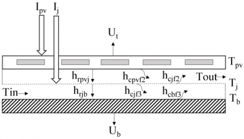
Figure 1. Energy balance of bifacial PVT
Table 1. Energy balance equations
|
|
|
$I_{p v}=U_{t}\left(T_{p v}-T_{a}\right)+h_{r p v j}\left(T_{p v}-T_{j}\right)+h_{c p v f 2}\left(T_{p v}-T_{f 2}\right)$ (1) where, $T_{p v}$=PV temperature; $T_{a}$=Ambient temperature; $T_{j}$=Jet plate reflector temperature; $T_{f 2}$=Upper air flow temperature. Part of the heat gain at the PV panel ($I_{p v}$) from the sunlight is dissipated through: a) Top loss ($U_{t}$) to the ambient and sky. b) Radiative heat transfer to jet plate reflector ($h_{r p v j}$). c) Convective heat transfer to upper air flow ($h_{\text {cpvf } 2}$). |
|
|
|
|
$h_{c p v f 2}\left(T_{p v}-T_{f 2}\right)+h_{c j f 2}\left(T_{j}-T_{f 2}\right)=2 \dot{m} \mathrm{C}_{p}\left(T_{f 2}-T_{f 2 i}\right) / W L$ (2) where, $\dot{m}$=Mass flow rate; $C_{p}$=Specific heat capacity; $T_{f 2 i}$=Temperature of inlet air at upper channel; W=Width of collector; L=Length of collector. Upper air flow gain heat from PV panel and jet plate reflector through convective heat transfer ($h_{c p v f 2}$ and $h_{c j f 2}$), then generate useful heat gain. |
|
|
|
|
$I_{j}+h_{r p v j}\left(T_{p v}-T_{j}\right)=h_{r j b}\left(T_{j}-T_{b}\right)+h_{c j f 1}\left(T_{j}-T_{f 1}\right)+h_{c j f 2}\left(T_{j}-T_{f 2}\right)$ (3) where, $T_{b}$=Backplate temperature; $T_{f 1}$= Lower air flow temperature. Jet plate reflector gained heat from the sunlight ($I_{j}$) and bifacial PV panel through radiation ($h_{r p v j}$). The heat is then transferred to backplate ($h_{r j b}$) through radiation and upper and lower air flow through convection ($h_{c j f 1}$ and $h_{c j f 2}$). |
|
|
|
|
$h_{c j f 1}\left(T_{j}-T_{f 1}\right)+h_{c b f 1}\left(T_{b}-T_{f 1}\right)=2 \dot{m} \mathrm{C}_{p}\left(T_{f 1}-T_{f 1 i}\right) / W L$ (4) where, $T_{f 1 i}$= Temperature of inlet air at lower channel. Lower air flow gain heat from jet plate reflector and backplate through convective heat transfer ($h_{c j f 1}$ and $h_{c b f 1}$), then generate useful heat gain |
|
|
|
|
$h_{r j b}\left(T_{j}-T_{b}\right)=U_{b}\left(T_{b}-T_{a}\right)+h_{c b f 1}\left(T_{b}-T_{f 1}\right)$ (5) Part of the heat gain at the backplate ($I_{p v}$) from the jet plate reflector through radiation is dissipated through: a) Bottom loss ($U_{b}$) from the backplate with insulation. b) Convective heat transfer to bottom air flow ($h_{c b f 1}$). |
A one-dimensional heat flow analytical model in steady state is developed to identify the energy balance between each component of the system. The heat transfer coefficients for each system component are presented in Figure 1. To assess the thermal and electrical efficiencies, and energy analysis was conducted. Assumptions were established for the bifacial PVT model to ease the analytical study, which is based on Fudholi et al. [14, 21]:
Table 1 illustrated the energy balance equations for each component of the system are shown.
The total energy collected by the solar collector from solar radiation is divided into two parts:
i) Heat gain at the jet plate reflector, $I_{j}=I \tau_{l}(1-P)\left(1-\eta_{R}\right)$.
ii) Heat gain at the bifacial PV panel, $I_{p v}=I_{p v f r o n t}+I_{\text {pvrear }}$.
In order to account for the heat energy received by the front and rear surfaces of the bifacial PV panel,
$I_{p v \text { front }}=I \alpha_{p v} P\left(1-\eta_{\text {pvfront }}\right)+I \alpha_{l}(1-P)$ (6)
$I_{\text {pvrear }}=I \tau_{l}(1-P) \eta_{R} \alpha_{p v} P\left(1-\eta_{\text {pvrear }}\right)+I \tau_{l}(1-P) \eta_{R} \alpha_{l}(1-P)$ (7)
2.2 Determination of temperature for components of air heaters
The above Eqns. (1) to (5) in Table 1 may be expressed as a 5x5 matrix to determine the various solar air heater part temperatures, [A][T] = [C].
$\left[\begin{array}{ccccc}\mathrm{A} 1 & -h_{c p v f 2} & -h_{r p v j} & 0 & 0 \\ -h_{c p v f 2} & \mathrm{~A} 2 & -h_{c j f 2} & 0 & 0 \\ -h_{r p v j} & -h_{c j f 2} & \mathrm{~A} 3 & -h_{c j f 1} & -h_{r j b} \\ 0 & 0 & -h_{c j f 1} & \mathrm{~A} 4 & -h_{c b f 1} \\ 0 & 0 & -h_{r j b} & -h_{c b f 1} & \mathrm{~A} 5\end{array}\right]$
$\left[\begin{array}{c}T_{p v} \\ T_{f 2} \\ T_{j} \\ T_{f 1} \\ T_{b}\end{array}\right]=\left[\begin{array}{l}C 1 \\ C 2 \\ C 3 \\ C 4 \\ C 5\end{array}\right]$ (8)
$\mathrm{A} 1=U_{t}+h_{r p v j}+h_{c p v f 2}$ (9)
$\mathrm{A} 2=h_{c p v f 2}+h_{c j f 2}+2 \dot{m} \mathrm{C}_{p} /(\mathrm{WL})$ (10)
$\mathrm{A} 3=h_{r p v j}+h_{c j f 1}+h_{c j f 2}+h_{r j b}$ (11)
$\mathrm{A} 4=h_{c j f 1}+2 \dot{m} \mathrm{C}_{p} /(\mathrm{WL})+h_{c b f 1}$ (12)
$\mathrm{A} 5=h_{r j b}+U_{b}+h_{c b f 1}$ (13)
$\mathrm{C} 1=I_{p v}+U_{t} T_{a}$ (14)
$\mathrm{C} 2=2 \dot{m} \mathrm{C}_{p} T_{f 2 i} /(\mathrm{WL})$ (15)
$\mathrm{C} 3=I_{j}$ (16)
$\mathrm{C} 4=2 \dot{m} \mathrm{C}_{p} T_{f 1 i} /(\mathrm{WL})$ (17)
$\mathrm{C} 5=U_{b} T_{a}$ (18)
In Eq. (8), the mean temperature vectors may be computed using the matrix inversion method in the MATLAB simulation code [T]=[A]-1[C].
2.3 Heat transfer coefficients
For top loss coefficient: $U_{t}$ is given by [21]:
$U_{t}=\frac{1}{\left(h_{w}+h_{r p v s} \quad \right)^{-1}}$ (19)
where convective heat transfer of wind, $h_{w}$ is given by:
$h_{w}=5.7 \times 3.8\left(V_{w}\right)$ (20)
and radiative heat transfer coefficient from PV panel to the sky, $h_{r p v s}$ is given by:
$h_{r p v s}=\sigma \epsilon_{p v}\left(T_{p v}+T_{s}\right)\left(T_{p v}{ }^{2}+T_{s}^{2}\right)\left(T_{p v}-T_{s}\right) /\left(T_{p v}-T_{a}\right)$ (21)
and temperature of sky, $T_{s}$ is given by:
$T_{s}=0.0552\left(T_{a}^{1.5}\right)$ (22)
For radiative heat transfer coefficient between PV panel, jet plate reflector, and backplate, $h_{r p v j}$ & $h_{r j b}$ is given by [14]:
$h_{r p v j}=\sigma\left(T_{p v}+T_{j}\right)\left(T_{p v}^{2}+T_{j}^{2}\right) /\left(\frac{1}{\varepsilon_{p v}}+\frac{1}{\varepsilon_{j}}-1\right)$ (23)
$h_{r j b}=\sigma\left(T_{j}+T_{b}\right)\left(T_{j}^{2}+T_{b}^{2}\right) /\left(\frac{1}{\varepsilon_{j}}+\frac{1}{\varepsilon_{b}}-1\right)$ (24)
For convective heat transfer coefficient between PV panel and airflow in the upper channel, $h_{c p v f 2}$ is given by [12]:
$h_{c p v f 2}=k \times N u_{p v f 2} / D_{h}$ (25)
where, Nusselt number, $N u_{p v f 2}$ is given by:
$N u_{p v f 2}\left(1.658 \times 10^{-3}\right)\left(R e_{2}^{0.8512}\right)\left(\frac{X}{D_{h}}\right)^{0.1761}\left(\frac{Y}{D_{h}}\right)^{0.141}\left(\frac{D_{j}}{D_{h}}\right)^{-1.9854} \times$
$e^{\left(-0.3498 \times\left(\log \left(\frac{D_{j}}{D_{h}}\right)\right)^{2}\right)}$ (26)
For convective heat transfer coefficient between jet plate reflector and airflow in upper & lower channel, $h_{c j f 2}$ & $h_{c j f 1}$ is given by [10]:
$h_{c j f 2}=\left(\frac{A_{e}}{A_{c}}\right) \times k \times N u_{j f 2} / D_{h}$ (27)
$h_{c j f 1}=\left(\frac{A_{e}}{A_{c}}\right) \times k \times N u_{j f 1} / D_{h}$ (28)
where, Nusselt number, $N u_{j f 2}$ & $N u_{j f 1}$ is given by:
$N u_{j f 2}=0.0293\left(R e_{2}^{0.8}\right)$ (29)
$N u_{j f 1}=0.0293\left(R e_{1}^{0.8}\right)$ (30)
and effective heat transfer area of the jet plate, $A_{e}$ is given by:
$A_{e}=A_{c}-N \pi D_{j}^{2}+2 N_{T} N$ (31)
For convective heat transfer coefficient between backplate and airflow in the lower channel, $h_{c b f 1}$ is given by [14]:
$h_{c b f 1}=h_{c j f 1} \times\left(\frac{A_{c}}{A_{e}}\right)$ (32)
For the bottom lost coefficient, $U_{b}$ is given by:
$U_{b}=k_{i n} / t_{i n}$ (33)
For hydraulic diameter, $D_{h}$ is given by:
$D_{h}=\left(\frac{4 W d}{2(W+d)}\right)$ (34)
For Reynolds number, Re is given by:
$R e=\frac{\dot{m} D_{h}}{W d \mu}$ (35)
For physical properties of air which are assumed to vary linearly with temperature in Kelvin is according to empirical correlations proposed by Ong et al. [22-24], is listed below:
Specific heat capacity of air, $C_{p}$ is given by:
$C_{p}=1.0057+0.000066(T-300)$ (36)
The density of air, ρ is given by:
$\rho=1.1774-0.00359(T-300)$ (37)
Thermal conductivity of air, k is given by:
$k=0.02624+0.0000758(T-300)$ (38)
The viscosity of air, μ is given by:
$\mu=[1.983+0.00184(T-300)] \times 10^{-5}$ (39)
2.4 Energy efficiency
For the thermal energy efficiency of the system, $\eta_{thermal} \quad$ can be calculated by:
$\eta_{\text {thermal }}=\frac{Q u}{\left(I \times A_{C}\right)}$ (40)
where useful heat gain, $Q u$ can be calculated by:
$Q u=\dot{m} C_{p}\left(T_{o}-T_{i}\right)$ (41)
For the electrical energy efficiency of the system, $\eta_{panel}$ can be calculated by [25]:
$\mathbf{\eta}_{\text {panel }}=\frac{P_{\max }}{I A_{C}}$ (42)
where electrical power generated, $P_{\max }$ can be calculated by [23]:
$P_{\max }=I A_{c} \alpha_{p v} P\left(\mathrm{\eta}_{pvfront}\right)+I A_{c} \tau_{l}(1-P) \eta_{R} \alpha_{p v} P\left(\eta_{\text {pvrear }}\right)$ (43)
and front & rear part of bifacial PV cell efficiency, $\mathrm{\eta}_{\text {pvfront }} \& \mathrm{\eta}_{\text {pvrear }}$ can be calculated by [18]:
$\mathrm{n}_{\text {pvfront }}=\mathrm{\eta}_{\text {pvrear }}=\mathrm{\eta}_{\text {ref }}\left(1-B\left(T_{p v}-T_{\text {ref }}\right)\right.$ (44)
2.5 Simulation flowchart
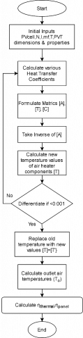
Figure 2 below shows the simulation flowchart through MATLAB for this analytical study.
Figure 2. Flowchart for simulation through MATLAB
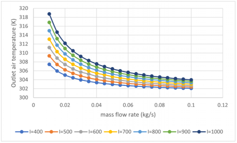
The thermal efficiency and outlet air temperatures vs. mass flow rate are shown in Figures 3-4 below. The output temperature falls as the mass flow rate rises. This is because greater airspeed increases the heat transfer rate between the flowing fluid and the collector's components. As a result, the heat from the collector's components will be removed from the flowing fluid more quickly. Consequently, the collector's components will get colder, and the temperature of the output air will drop. At higher mass flow rate, the rate of heat transfer is higher, which led to lower outlet temperature. However, the cooling effect of the jet impingement will decrease when it nearly achieved stable state, where the difference of the outlet and inlet air temperature is smaller. Therefore, the variation between 2 consecutive points of the outlet temperature decreases. Hence, the temperature in Figure 3 start to fall fast and then slow down as the mass flow rate increase.
Furthermore, the thermal efficiency of the collector will improve as the rate of heat transfer increases. Overall, thermal efficiency is related to mass flow rate, while the output air temperature is proportional to mass flow rate. Higher solar irradiation increases the collector's heat uptake, which raises the temperature of the collector's components. As a result, the output air temperature rises, as does the thermal efficiency.
Figure 3. Outlet air temperature versus mass flow rate
Figure 4. Thermal efficiency versus mass flow rate
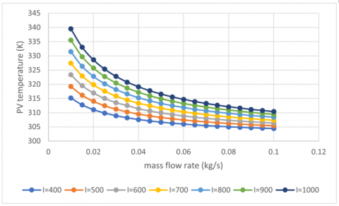
Figure 5. PV temperature versus mass flow rate
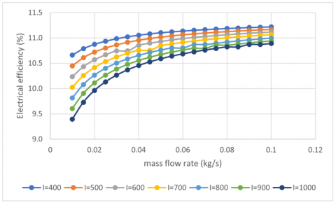
The electrical efficiency and temperature of the bifacial PV panel are shown against mass flow rate in Figures 5-6 below. As the rate of mass flow rises, the bifacial PV panel's temperature drops. This is because greater airspeed accelerates heat transfer between the flowing fluid and the PV panel. As a result, the heat from the PV panel will be removed from the flowing fluid more quickly.
As a consequence, the PV panel will get more relaxed, and its temperature will drop. Because the PV panel works at a lower temperature, it generates more energy, increasing electrical efficiency. Overall, electrical efficiency is related to mass flow rate, while PV panel temperature is inversely proportional to mass flow rate. Higher solar irradiation increases the collector's heat uptake, which raises the temperature of the PV panel. As a result, the PV panel will run at a greater temperature, and the electrical efficiency will suffer.
Figure 6. Electrical efficiency versus mass flow rate
In conclusion, this study presented an analytical investigation on the performance of Bifacial photovoltaic-thermal (PVT) air heater with jet plate reflector. A novel design of hybrid system with combination of bifacial PV panel and jet plate reflector is demonstrated. Energy balance for the proposed system was studied and equations were formed to determine the temperature for components of air heaters. Energy analysis was conducted to identify the optimum thermal and electrical efficiencies of the system. Moreover, the effects of mass flow rate and solar irradiance on the performance of the system were analyzed and discussed.
A greater mass flow rate reduces the exit air temperature and increases the thermal efficiency of the thermal component. On the other hand, increased sun irradiation raises the output air temperature and thermal efficiency. In terms of electrical efficiency, a greater mass flow rate reduces the temperature of the PV panel while increasing electrical efficiency. However, higher solar irradiation raises the temperature of the PV panel, lowering its electrical efficiency. The maximum thermal efficiency of BPVTJPR is 51.09% under the circumstances of 12 PV cells with a packing factor of 0.66, a jet plate reflector with 36 holes, 900 W/m2 solar irradiances, and a mass flow rate of 0.035 kg/s. The maximum electrical efficiency of BPVTJPR is 10.73% under the circumstances of 12 PV cells with a packing factor of 0.66, a jet plate reflector with 36 holes, 700 W/m2 solar irradiances, and a mass flow rate of 0.035 kg/s.
Using bifacial PV panel is an efficient way to increase to total surface area for solar absorption, which led to higher electricity generation. Jet impingement cooling method was used to increase the rate of heat transfer so that the bifacial PV panel can operate in low temperature for higher electrical efficiency. The combination of jet plate with reflector enhanced the cooling effect, at the same time, enabled the reflection of light to the rear surface of the panel. Consequently, BPVTJPR is a high efficiency solar collector with high thermal and electrical output. For future studies, experimental work or CFD simulation is suggested to perform extensive study on the performance of the proposed system.
The authors would like to thank UKM for its funding (GUP-2018-128).
[1] Geng, Y., Ji, W., Wang, Z., Lin, B., Zhu, Y. (2019). A review of operating performance in green buildings: Energy use, indoor environmental quality and occupant satisfaction. Energy and Buildings, 183: 500-514. https://doi.org/10.1016/j.enbuild.2018.11.017
[2] Hwang, B.G., Shan, M., Supa’at, N.N.B. (2017). Green commercial building projects in Singapore: Critical risk factors and mitigation measures. Sustainable Cities and Society, 30: 237-247. https://doi.org/10.1016/j.scs.2017.01.020
[3] Hwang, B.G., Shan, M., Xie, S., Chi, S. (2017). Investigating residents’ perceptions of green retrofit program in mature residential estates: The case of Singapore. Habitat International, 63: 103-112. https://doi.org/10.1016/j.habitatint.2017.03.015
[4] Desa, U.N. (2014). World urbanization prospects, the 2011 revision. Population Division, Department of Economic and Social Affairs, United Nations Secretariat.
[5] Houghton, A., Castillo-Salgado, C. (2020). Analysis of correlations between neighborhood-level vulnerability to climate change and protective green building design strategies: A spatial and ecological analysis. Building and Environment, 168: 106523. https://doi.org/10.1016/j.buildenv.2019.106523
[6] United Nations (2009). Buildings and Climate Change. https://www.uncclearn.org/wp-content/uploads/library/unep207.pdf.
[7] Sansaniwal, S.K., Sharma, V., Mathur, J. (2018). Energy and exergy analyses of various typical solar energy applications: A comprehensive review. Renewable and Sustainable Energy Reviews, 82: 1576-1601. https://doi.org/10.1016/j.rser.2017.07.003
[8] Pawar, R.S., Takwale, M.G., Bhide, V.G. (1994). Evaluation of the performance of the solar air heater. Energy Conversion and Management, 35(8): 699-708. https://doi.org/10.1016/0196-8904(94)90054-X
[9] Forson, F.K., Nazha, M.A., Rajakaruna, H. (2003). Experimental and simulation studies on a single pass, double duct solar air heater. Energy Conversion and Management, 44(8): 1209-1227. https://doi.org/10.1016/S0196-8904(02)00139-5
[10] Choudhury, C., Garg, H.P. (1991). Evaluation of a jet plate solar air heater. Solar Energy, 46(4): 199-209. https://doi.org/10.1016/0038-092X(91)90064-4
[11] Belusko, M., Saman, W., Bruno, F. (2008). Performance of jet impingement in unglazed air collectors. Solar Energy, 82(5): 389-398. https://doi.org/10.1016/j.solener.2007.10.005
[12] Chauhan, R., Thakur, N.S. (2013). Heat transfer and friction factor correlations for impinging jet solar air heater. Experimental Thermal and Fluid Science, 44: 760-767. https://doi.org/10.1016/j.expthermflusci.2012.09.019
[13] Chan, H.Y., Vinson, A.A., Baljit, S.S.S., Ruslan, M.H. (2018). Comparison of thermal performances between low porosity perforate plate and flat plate solar air collector. In Journal of Physics: Conference Series, 989(1): 012001. https://doi.org/10.1088/1742-6596/989/1/012001
[14] Matheswaran, M.M., Arjunan, T.V., Somasundaram, D. (2018). Analytical investigation of solar air heater with jet impingement using energy and exergy analysis. Solar Energy, 161: 25-37. https://doi.org/10.1016/j.solener.2017.12.036
[15] Chow, T.T. (2010). A review on photovoltaic/thermal hybrid solar technology. Applied Energy, 87(2): 365-379. https://doi.org/10.1016/j.apenergy.2009.06.037
[16] Takashima, T., Tanaka, T., Doi, T., Kamoshida, J., Tani, T., Horigome, T. (1994). New proposal for photovoltaic-thermal solar energy utilization method. Solar Energy, 52(3): 241-245. https://doi.org/10.1016/0038-092X(94)90490-1
[17] Brideau, S.A., Collins, M.R. (2014). Development and validation of a hybrid PV/Thermal air based collector model with impinging jets. Solar Energy, 102: 234-246. https://doi.org/10.1016/j.solener.2014.01.022
[18] Ooshaksaraei, P., Sopian, K., Zaidi, S.H., Zulkifli, R. (2017). Performance of four air-based photovoltaic thermal collectors configurations with bifacial solar cells. Renewable Energy, 102: 279-293. https://doi.org/10.1016/j.renene.2016.10.043
[19] Hasan, H.A., Sopian, K., Jaaz, A.H., Al-Shamani, A.N. (2017). Experimental investigation of jet array nanofluids impingement in photovoltaic/thermal collector. Solar Energy, 144: 321-334. https://doi.org/10.1016/j.solener.2017.01.036
[20] Hasan, H.A., Sopian, K., Fudholi, A. (2018). Photovoltaic thermal solar water collector designed with a jet collision system. Energy, 161: 412-424. https://doi.org/10.1016/j.energy.2018.07.141
[21] Fudholi, A., Mustapha, M. (2020). Mathematical modelling of bifacial photovoltaic-thermal (BPVT) collector with mirror reflector. International Journal of Renewable Energy Research (IJRER), 10(2): 654-662.
[22] Ong, K.S. (1995). Thermal performance of solar air heaters: Mathematical model and solution procedure. Solar Energy, 55(2): 93-109. https://doi.org/10.1016/0038-092X(95)00021-I
[23] Sun, X., Khan, M.R., Deline, C., Alam, M.A. (2018). Optimization and performance of bifacial solar modules: A global perspective. Applied Energy, 212: 1601-1610. https://doi.org/10.1016/j.apenergy.2017.12.041
[24] Mohelníková, J., Altan, H. (2009). Evaluation of optical and thermal properties of window glazing. WSEAS Transactions on Environment and Development, 5(1): 86-93.