Sylvie Bégot* | Muluken Z. Getie | Alpha Diallo | François Lanzetta | Magali Barthès | Michel de Labachelerie
© 2021 IIETA. This article is published by IIETA and is licensed under the CC BY 4.0 license (http://creativecommons.org/licenses/by/4.0/).
OPEN ACCESS
In this paper, we present a new model and design of a MEMS Stirling machine. The concept could be used to provide electricity to low level power systems. A modified adiabatic model including losses of a Stirling engine such as regenerator thermal efficiency, wall conduction, pressure drop, hysteresis, membrane finite speed and squeeze film damping losses is presented. A base design machine is proposed. A parametric study is conducted and used to derive guidelines for miniature design. Compared to macro-scale design, the same trend was observed for the influence of the thermal performance regenerator. However, different trends from macroscopic engines were observed: conduction losses are of major importance due to the low power of the miniature engines, hysteresis losses in the bounce space are also of high amplitude due to the small size if this volume, the choice of the working gas leads to hydrogen or air and not helium. We computed that membrane finite speed losses and squeeze film damping losses can be neglected in the investigated machine size. The first part of the paper presents the micro-machine specific features, the second part describes the model, the last part presents the base design results and design guidelines.
adiabatic modelling, design guidelines, downsizing effects, engine, MEMS, Stirling
Billions of items consuming low level power may significantly contribute to global energy consumption and CO2 emissions. Therefore, the use of a renewable source to produce locally the electric power needed by these devices [1] appears to have a significant potential for energy savings. Among renewable sources, waste heat has a large potential. Unfortunately, most of the waste heat losses are at low temperature: one-third of the waste heat is below 200℃, and another 25% is between 200℃ and 500℃ [2]. Few technologies present good technical-and-economical performances for low temperature waste heat recovery. On the other hand, MEMS (Microelectromechanical systems) technology is well suited to these temperatures and presents low costs due to batch manufacturing. Therefore, it would be interesting to investigate the use of MEMS power conversion machines operating on waste heat for the low power devices.
Among these technologies, Stirling engines seem a good candidate because of their ability to use external heat sources. The Stirling machine was invented by Robert Stirling in 1816 [3]. It can operate as an engine or as a cooler by reversing the thermodynamic cycle. Since 1816, several developments led to applications in various fields such as solar converters of combined heat and power [4-6] for example. Whereas numerous works deal with Stirling engines at a macroscopic scale [7], only a few works concern miniaturized Stirling engines. The first prototype on a centimeter scale was developed by Nakajima et al. in 1989 [8]. It included a 0.05 cm3 swept volume and delivered a power of 10 mW at 10 Hz operating between temperatures of 273 K and 373 K. In 2002, Moran patented a micro-cooler made up from a Stirling micromachine [9]. Silicon membranes, electrostatically actuated, played the role of the pistons. Several types of regenerators were tested [10]. After experimental tests between 100 and 1000 Hz, no notable difference in temperature between the chambers was observed. In 2015, Formosa and Fréchette proposed and modeled a multiphase membrane machine for thermal heat harvesting [11]. It consisted of three coupled elementary phases, each composed of a 5 mm-diameter membrane which acted as a piston and transducer integrating a piezoelectric planar spiral, an expansion chamber, and a compression chamber linked by a regenerator.
To conclude, Stirling machines at macroscopic scale are a well known technology, but except for the centimetric engine designed by Nakajima et al., micro-scale Stirling cycles machines are not operating yet. Therefore, it seems appropriate to investigate Stirling engines at micro-scale by developing and adapting a complete thermodynamic model to the specificity of micro-scale design. This is the main topic of the paper. The novelty of the work is a comprehensive adiabatic model including not only pressure drop losses, conduction losses and regenerator thermal effectiveness but also hysteresis, finite speed and squeeze film damping losses. The use of hydrogen and helium as working gas at this scale is also analyzed. The guidelines that result from this model application are also a main point of this work.
The first part of the paper presents the principle of the Stirling cycle, and the micro-machines specific features. The second part describes the model. The last part of the paper presents the base design characteristics and results. Parametric studies are presented. From these results, design guidelines for miniature engines are provided.
2.1 Ideal Stirling cycle
The ideal Stirling cycle [3] includes 4 thermodynamic transformations:
The efficiency of this ideal cycle is the Carnot efficiency:
$\eta=1-T_{e} / T_{c}$ (1)
2.2 Mechanical configuration
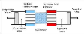
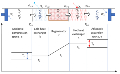
An Alpha configuration Stirling engine includes two cylinders and two pistons (Figure 1) [3]. A regenerator connects the expansion and compression spaces. The movements of the pistons allow the gas to follow the Stirling cycle. The regenerator stores the heat of the fluid during the transfer of the gas from the hot part to the cold part and restores it in the opposite direction. Two heat exchangers, one at the hot source and one at the cold sink, are also necessary. A part of the machine, not represented on Figure 1 contains the mechanical drive that links the pistons. The volume of this part can also be pressurized and is called the bounce space.
Figure 1. Alpha configuration
2.3 Micro-machine specific features
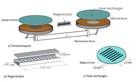
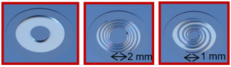
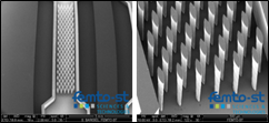
At micro-scale level, the Stirling machine design has to be adapted for technological reasons as MEMS fabrication relies on techniques that are used in integrated circuit technology rather than mechanical engines technology. Generally, a silicon substrate is used, then the process adds or removes layers before the final assembly and packaging [12]. These technological choices have an impact on the model equations, for this reason, the model is detailed after defining the micro-scale design main features. The general layout of the machine is presented in Figure 2a as an exploded view. We choose an Alpha configuration because the symmetry of the compression and expansion chambers are adapted to batch fabrication. The micro-machine includes two cylinders mechanically coupled. The cylinder volumes are swept by membranes. Both cylinders are closed in their upper part by plates used as heat exchangers (Figure 2c). Channels are etched on the heat exchangers plates to promote heat transfer. A regenerator connects the hot and cold heat exchangers (Figure 2b). In macro-scale design, pistons are used but are not practical at microscale [9], therefore the membrane is a hybrid membrane made from a center silicon disk embedded in RTV silicone (Figure 3). More details on the design and fabrication are given in Diallo et al. works [13, 14] where the technological feasibility of this membrane was established. In the same way, the regenerator in macro-scale design is usually made from woven screens, metal felts or involute foils. In our case, these technologies are not applicable, therefore we choose to use an array of pillars to fulfill the function of regeneration (Figure 2b). The machine materials that can be used are those adapted to clean rooms facilities and batch fabrication. Therefore, the chosen base materials are glass and silicon that are usually available as wafers [12]. Due its higher thermal conductivity, silicon is used where heat exchange is needed: heat exchangers plates and regenerator pillars. Glass is used when heat exchange is detrimental: regenerator walls to limit the heat transfer from the hot part of the machine to the cold part. The fabrication of the regenerator includes a first step where a glass wafer and silicon wafer are assembled by anodic bonding, then the pillars are etched by Deep Reactive Ion Etching (DRIE). More details on the design, fabrication and CFD modeling of the regenerator can be found in reference [15] (Figure 4).
Figure 2. Design of the Alpha micromachine
Figure 3. Membranes of the micromachine
Figure 4. Scanning Electron Microscopy images of the regenerator
Figure 5. Adiabatic model
3.1 Ideal adiabatic analysis adapted to micromachines
In real Stirling cycle machines, the compression and expansion processes tend to the adiabatic rather than isothermal. Therefore, we use the following assumptions to describe the cycle [16]:
• the working gas is ideal,
• the kinetic and potential energies of gas streams are negligible,
• all processes are performed at steady-state condition,
• the compression and expansion spaces are adiabatic,
• the temperature in the hot and cold heat exchangers are constant,
• heat is transferred to the working fluid only in the hot and cold heat exchangers,
• the temperature change of the working fluid in the regenerator is linear.
The analysis is based on the development presented by Urieli and Berchowitz [16] where all the derivation details can be found. The machine is divided into 5 volumes (Figure 5).
The analysis leads to the differential equations for pressure P, masses in the different volumes m, heat exchange in the heat exchangers Q, temperature T in the various volumes, and expression for the adiabatic work $W_{a d}$. They are briefly recalled here:
$m_{c}+m_{k}+m_{r}+m_{h}+m_{e}=m_{t}$ (2)
$d m_{c}=\frac{P d V_{c}+\frac{V_{c} d P}{\gamma}}{R T_{c k}}$ (3)
$d m_{e}=\frac{P d V_{e}+\frac{V_{e} d P}{\gamma}}{R T_{h e}}$ (4)
$P=\frac{m_{t} R}{\frac{V_{c}}{T_{c}}+\frac{V_{h}}{T_{h}}+\frac{V_{r}}{T_{r}}+\frac{V_{c r}}{T_{c r}}+\frac{V_{e}}{T_{e}}}$ (5)
$d P=-\frac{P \gamma\left(\frac{d V_{c}}{T_{c k}}+\frac{d V_{e}}{T_{h e}}\right)}{\frac{V_{c}}{T_{c k}}+\gamma\left(\frac{V_{k}}{T_{k}}+\frac{V_{r}}{T_{r}}+\frac{V_{h}}{T_{h}}\right)+\frac{V_{e}}{T_{h e}}}$ (6)
$d Q_{k}=\frac{V_{k} d P C_{v}}{R}-C_{p}\left(T_{c k} \dot{m}_{c k}-T_{k r} \dot{m}_{k r}\right)$ (7)
$d Q_{r}=\frac{V_{r} d P C_{v}}{R}-C_{p}\left(T_{k r} \dot{m}_{k r}-T_{r h} \dot{m}_{r h}\right)$ (8)
$d Q_{h}=\frac{V_{h} d P C_{v}}{R}-C_{p}\left(T_{r h} \dot{m}_{r h}-T_{h e} \dot{m}_{h e}\right)$ (9)
$d T_{e}=T_{e}\left(\frac{d P}{P}+\frac{d V_{e}}{V_{e}}-\frac{d m_{e}}{m_{e}}\right)$ (10)
$d T_{c}=T_{c}\left(\frac{d P}{P}+\frac{d V_{c}}{V_{c}}-\frac{d m_{c}}{m_{c}}\right)$ (11)
$W_{a d}=\oint_{c y c l e}\left(P d V_{c}+P d V_{e}\right)$ (12)
This set of differential equations is solved iteratively by a Runge-Kutta method. This model was validated against the macroscopic GPU3 engine results [17].
3.2 Modified ideal adiabatic analysis adapted to micromachines
This ideal model is not accurate enough to predict the engine performances. It is necessary to compute various losses to enhance the model accuracy. Among the losses that are usually accounted for in macroscopic Stirling engines [16, 18, 19], shuttle heat losses, mass leakage losses and piston friction losses are not relevant due to the use of membranes instead of pistons. On the other hand, losses due the non-ideal heat transfer in the regenerator, direct conduction, pressure drop, hysteresis, piston finite speed are relevant at both scales. The micro-scale design also leads to analyze squeeze film damping losses [20]. Non-ideal heat transfer of the regenerator is included in the set of the differential equations. It leads to correct the temperatures in the hot and cold heat exchangers following the "simple" algorithm proposed by Urieli and Berchowitz [16]. The other losses are subtracted to the overall engine power. For a Stirling cycle engine having a non-ideal regenerator, when the working gas flows from the cold heat exchanger to the hot heat exchanger, the gas do not recover all the heat ideally stored in the regenerator. The thermal energy regenerator losses $Q_{r l}$ are given by:
$Q_{r l}=m C_{p}(1-\epsilon)\left(T_{c}-T_{e}\right)$ (13)
where, ϵ denotes the regenerator efficiency. This efficiency is defined by using the Number of the Transfer Units (NTU) as:
$\epsilon=\frac{N T U}{N T U+1}$ (14)
The NTU is related to the Stanton number St through:
$N T U=\operatorname{St} \frac{A_{w g, r}}{2 A_{r}}$ (15)
where, $A_{w g r}$ and $A_{r}$ denote the regenerator wetted area, and free flow area respectively. The Stanton number is computed from the friction factor following the Reynolds analogy:
$S t=\frac{f_{r}}{2 R e P r}$ (16)
where, $R e, P r, f_{r}$ are the Reynolds number, Prandtl number and Fanning friction factor. The correlation used to determine the friction factor is detailed in §3.2.2. Thus, the net heat absorbed from the hot heat exchanger and net heat released to the cold heat exchanger at their respective wall temperatures by the working gas per cycle are given by:
$Q_{k}=Q_{k, \text { ideal }}-Q_{r l}=\frac{h_{k} A_{w g, k}\left(T_{w, k}-T_{k}\right)}{f}$ (17)
$Q_{h}=Q_{h, \text { ideal }}+Q_{r l}=\frac{h_{h} A_{w g, h}\left(T_{w, h}-T_{h}\right)}{f}$ (18)
where, Qh,ideal, Qk,ideal denote the heat absorbed or released of the ideal adiabatic analysis, i.e. without taking into account the regenerator thermal effectiveness, f denotes the frequency of operation. From Eq. (17) and Eq. (18), the gas temperatures in the heat exchangers can be computed.
3.2.1 Heat losses due to wall conduction in the regenerator
In Stirling cycle machines, regenerators are physically located between the hot heat exchanger and cold heat exchanger. In a micromachine, the distance between the hot and cold part of the machine are small, therefore, direct conduction heat losses are of primary importance. The amount of energy losses Qwrl caused by heat conduction in the regenerator walls is found as follows [19]:
$Q_{w r l}=k_{r} \frac{A_{w, r}}{L_{r} f}\left(T_{w, h}-T_{w, k}\right)$ (19)
where, kr is the regenerator wall conductivity (Table 1), Awr is the surface of the wall, Lr is the regenerator length, Twh and Twk are the hot and cold heat exchanger wall temperature and f is the frequency of operation. Other conduction losses in the machine are supposed to be negligible compared to the regenerator wall conduction losses.
3.2.2 Friction factors and heat exchange coefficients in heat exchangers
The regenerator is made of an array of micro pillars. Each pillar is approximated as a cylinder of elliptic cross-section. The Fanning friction factor is defined from the experimental work of Vanapalli et al. [21]:
$f_{r}=6.745 R e^{-0.82}$ (20)
where, Re is the Reynolds number based on the pillars array hydraulic diameter dH,r and average gas velocity over half a cycle.
The hydraulic diameter of the regenerator is defined as:
$d_{H, r}=\frac{4 \psi V_{r}}{A_{w g, r}}$ (21)
where, ψ is the regenerator porosity and Vr its volume.
The Stanton number and heat exchange coefficients are computed using the Reynolds analogy as explained in §3.2.1.
The cold and hot heat exchangers friction factors and heat exchange coefficients are chosen referring to non-circular ducts correlations in laminar flow:
$f_{r}=\frac{24}{R e}$ (22)
$N u=7.54$ (23)
3.2.3 Losses due to pressure drop in heat exchangers
The pressure drop losses in heat exchangers are calculated to evaluate the amount of power losses due to fluid friction losses. The amount of energy dissipated Wfr due to pressure drops at the hot heat exchanger, regenerator and cold heat exchanger is evaluated as:
$W_{f r}=\int_{c y c l e}\left(\Delta P \frac{d V_{e}}{d \theta}\right) d \theta$ (24)
where:
$\Delta P=\Delta P_{h}+\Delta P_{r}+\Delta P_{k}$ (25)
and
$\Delta P_{i}=\left(4 f_{r, i} \frac{L}{d_{H, i}}+K_{D, i}\right) \frac{\rho_{i} v_{g, i}^{2}}{2}$ (26)
where, vg,i is the mean gas velocity observed on half a cycle in the exchangers, and i=h,r,k.
Minor losses are also considered. At the interface of the regenerator and heat exchangers, a loss coefficient for a sudden contraction or expansion is defined as:
$K_{D, i}=0.3$ (27)
3.2.4 Losses due to finite speed of membrane
In the regenerative Stirling cycle machine, the working spaces are periodically compressed and expanded by the pistons or in our case by membranes. Based on the finite speed thermodynamic principles, the instantaneous pressure of compression and expansion spaces differs from the pressure in the respective membranes’ surfaces. The work losses due to finite speed of the membranes over a cycle is evaluated from this pressure drop as [18, 22]:
$W_{f s}=\oint_{c y c l e}^{} \Delta P_{f s} d V$ (28)
and
$\Delta P_{f s}=\frac{1}{2}\left(P \frac{a v_{m, c}}{c_{c}}+P \frac{a v_{m, e}}{c_{e}}\right)$ (29)
where, vm is the membrane mean speed, c is the average molecular speed $c=\sqrt{3 R T}$, and $a=\sqrt{3 \gamma}$. The membrane mean speed is defined as:
$v_{m}=2 s f$ (30)
where, s is the stroke of the membrane at its maximal deformation and f the frequency of operation.
3.2.5 Gas spring hysteresis losses
If the bounce space is closed, the gas in this volume is compressed and expanded periodically, thus acts as a gas spring. This thermodynamic process is not recoverable and may introduce additional losses in the engine that could be in the form of the dissipation of the gas spring fluid. This hysteresis power losses are modelled using the following expression [16]:
$\dot{W}_{h y s}=\sqrt{\frac{1}{32} \omega \gamma^{3}(\gamma-1) T_{w b} P k_{g}}\left(\frac{\Delta V_{b}}{V_{b}}\right)^{2} A_{w g, b}$ (31)
where, $\dot{W}_{h y s}, \omega, T_{w b}, P, \Delta V_{b}, V_{b}$ and $A_{w g, b}$ denote the hysteresis power losses, the angular speed of the machine, the bounce space wall temperature, the bounce space mean pressure, the variation of the bounce space volume, the total bounce space volume, and the wetted area of the bounce space respectively. We make the hypotheses that the bounce wall temperature is the same as the cold heat exchanger wall temperature $T_{w k}$ and that the mean pressure is the same as the machine mean pressure.
3.2.6 Squeeze film damping losses
As the volume forces that work on a machine vary in direct proportion to the cube of the length, while surface forces such as viscous force vary in direct proportion to the square of the length, surface forces that may be negligible at a macroscopic scale may play an important role in a micromachine [23]. Therefore, when miniaturizing Stirling engines, the issue of squeeze film damping has to be analyzed. The aim is to check that during the displacement between the expansion and compression spaces, the gas can escape the chambers. The squeeze number $\sigma$ is defined as [23]:
$\sigma=\frac{12 \mu r_{m}^{2} \omega}{P z^{2}}$ (32)
where, $r_{m}$ is the characteristic length of the device, in our case the radius of the membrane, and $z$ is the height of the film. In our case, $z$ is chamber height. When $\sigma<<1$, as it is the case in the base design, the Reynolds equation holds and the squeeze film damping force coefficient for a circular plate can be written as:
$D=\frac{3 \pi}{2 z^{3}} \mu r_{m}^{4}$ (33)
The damping force is computed as:
$F_{s f}=-D \dot{x}_{j}$ (34)
where, $\dot{x}$ is is velocity of the membrane, x its position and $j=c, e$. The work of the damping force over a cycle is computed as:
$W_{s f}=\oint_{c y c l e}^{\operatorname{}} \mathrm{F}_{s f} d x_{j}$ (35)
We derive the expressions of velocity from the sinusoidal variation of the swept volume:
$\frac{d x_{c}}{d \theta}=\frac{1}{2} \frac{V_{s w c}}{\pi r_{m}^{2}} \sin \theta$ (36)
Integrating leads to the expression of the loss due to squeeze film damping for the compression space:
$W_{s f, c}=\frac{\omega}{4} \frac{D V_{S w c}^{2}}{\pi r_{m}^{4}}$ (37)
The loss is identical for the expansion space. Thus:
$W_{s f}=\frac{\omega}{2} \frac{D V_{s w c}^{2}}{\pi r_{m}^{4}}$ (38)
3.2.7 Power and efficiency
The power $\dot{W}$ delivered by the engine and its efficiency are computed as:
$\dot{W}=\dot{W}_{a d}-\dot{W}_{f r}-\dot{W}_{f s}-\dot{W}_{s f}-\dot{W}_{h y s}$ (39)
$\eta=\frac{\dot{W}}{\dot{Q}_{i n}}$ (40)
where
$\dot{Q}_{i n}=\dot{Q}_{h}+\dot{Q}_{r l}+\dot{Q}_{w r l}$ (41)
In this section, a base design characteristics and model results are described. Then a parametric study is performed with a detailed analysis of the miniaturization effects. Design guidelines appropriate to micro-scale engine are derived.
4.1 Base design model characteristics
In this section, a proof of concept design is described, the various parameters are presented in Table 1. In this base design, the target power is 2 mW. The hot source temperature is supposed to be 200℃ (473 K), therefore it is within the temperature range of the considered low temperature waste heat. First, to fulfil the target power, the chamber diameter is chosen at 5 mm and the mean pressure at 0.15 MPa. The membrane thickness is 0.2 mm and its maximal deformation is 0.1 mm as it was demonstrated that this value is repeatable in the pressure range [13]. The total maximal deformation of the membrane is 0.2 mm. However, the membrane does not sweep the entire volume cylinder defined by the membrane surface and maximal deformation. In our base design case, the swept volume is considered to be 70% of this cylinder volume. So, the swept volume is 2.75 mm3. The chamber height is chosen at 0.23 mm. On the opposite side of the membrane, the bounce space volume is closed to protect the membrane. As in macroscopic engine, the bounce space volume is larger than the chamber volume and 20% of this volume is supposed to be swept. Its pressure is also the machine mean pressure. As in all Stirling engines, the volume of the heat exchangers is a trade-off between the heat exchange requirements, the pressure drop and dead volumes. In this design, the length of the heat exchangers ducts is limited by the chamber diameter, the number and depth of ducts by technology. A design of 6 ducts was chosen. The regenerator design is also a trade-off between the same elements. Its porosity is chosen at 0.8, a common value in macroscopic engines, and its length is 2 mm. The regenerator walls link the hot part of the machine to the cold part. Therefore, wall thickness is reduced to 0.05 mm to avoid conduction losses.
Table 1. Base design main parameters
|
Parameter |
Symbol |
Unit |
Values |
|
General |
|
|
|
|
Gas |
- |
- |
Air |
|
Mean pressure |
$P$ |
MPa |
0.15 |
|
Hot source temperature |
$T_{h}$ |
K |
473 |
|
Cold sink temperature |
$T_{k}$ |
K |
288 |
|
Frequency |
$f$ |
Hz |
100 |
|
Phase angle |
$\alpha$ |
degrees |
90 |
|
Chambers |
|
|
|
|
Membrane diameter |
$d_{m}$ |
mm |
5 |
|
Membrane stroke |
$s$ |
mm |
0.4 |
|
Chamber height |
$z$ |
mm |
0.23 |
|
Swept volume |
$V_{s w c}$ |
mm3 |
2.75 |
|
Bounce space |
|
|
|
|
Volume |
$V_{b}$ |
mm3 |
13.7 |
|
Volume variation |
$\Delta V_{b} / V_{b}$ |
% |
20 |
|
Height |
- |
mm |
0.7 |
|
Cold and hot heat exchangers |
|
|
|
|
Number of ducts |
- |
- |
6 |
|
Length |
$L_{h, k}$ |
mm |
2.5 |
|
Width |
- |
mm |
0.4 |
|
Height |
- |
mm |
0.075 |
|
Regenerator |
|
|
|
|
Length |
$L_{r}$ |
mm |
2 |
|
Porosity |
$\psi$ |
- |
0.8 |
|
Internal width |
- |
mm |
0.5 |
|
Internal height |
- |
mm |
0.1 |
|
Wall thickness |
- |
mm |
0.05 |
|
Wall thermal conductivity |
$k_{r}$ |
$W m^{-1} K^{-1}$ |
1 |
4.2 Base design model results
Applying the base design parameters to the modified adiabatic model leads to a 2.2 mW machine with an efficiency of 6% (Table 2) at 100 Hz. The various losses values are presented in Table 2 for an operating frequency of 100 Hz.
In order to derive some general analysis, dimensionless losses are computed: mechanical losses values are divided by the power issued from the adiabatic analysis $\dot{W}_{a d}$, and the thermal losses are divided by the hot heat power $\dot{Q}_{\text {in }}$. The resulting dimensionless variables and results are displayed in Table 3.
Compared to macroscopic machine losses distribution, such as those observed in the GPU3 engine [16], we observe that the regenerator thermal efficiency is also a main contributor to the losses, and so are the thermal conduction losses. Pressure drop is also a major concern at both scales. Hysteresis losses are very high in miniaturized Stirling engines, compared to macroscopic engines, therefore careful design should be used to minimize their impact. Finite speed and squeeze film damping lead to very small losses, finite speed losses being larger than squeeze film damping.
Table 2. Base design main results
|
|
Symbol |
Unit |
Values |
|
Power and efficiency |
|
|
|
|
Heat power in |
$\dot{Q}_{\text {in }}$ |
mW |
36.52 |
|
Heat power out |
$\dot{Q}_{k}$ |
mW |
14.32 |
|
Power out |
$\dot{W}$ |
mW |
2.21 |
|
Efficiency |
$\eta$ |
% |
6.04 |
|
Losses |
|
|
|
|
Regenerator inefficiency |
$\dot{Q}_{r l}$ |
mW |
9.43 |
|
Regenerator conduction |
$\dot{Q}_{w r l}$ |
mW |
7.77 |
|
Pressure drop |
$\dot{W}_{f r}$ |
mW |
0.64 |
|
Hysteresis |
$\dot{W}_{h y s}$ |
mW |
2.17 |
|
Piston finite speed |
$\dot{W}_{f s}$ |
mW |
$1.59 \times 10^{-4}$ |
|
Squeeze film damping |
$\dot{W}_{s f}$ |
mW |
$5.28 \times 10^{-6}$ |
Table 3. Base design dimensionless losses
|
Dimensionless losses |
Symbol |
Values |
|
Regenerator efficiency |
$\dot{Q}_{r l, \text { dless }}=\dot{Q}_{r l} / \dot{Q}_{\text {in }}$ |
0.49 |
|
Regenerator conduction |
$\dot{Q}_{w r l, \text { dless }}=\dot{Q}_{w r l} / \dot{Q}_{\text {in }}$ |
0.40 |
|
Pressure drop |
$\dot{W}_{f r, \text { dless }}=\dot{W}_{f r} / \dot{W}_{a d}$ |
0.13 |
|
Hysteresis |
$\dot{W}_{h y s, \text { dless }}=\dot{W}_{\text {hys }} / \dot{W}_{a d}$ |
0.43 |
|
Piston finite speed |
$\dot{W}_{f s, \text { dless }}=\dot{W}_{f s} / \dot{W}_{a d}$ |
3.2x10⁻⁵ |
|
Squeeze film damping |
$\dot{W}_{s f, d l e s s}=\dot{W}_{s f} / \dot{W}_{a d}$ |
1.05x10⁻⁶ |
4.3 Parametric analysis
4.3.1 Influence of operational parameters: hot source temperature, frequency and working gas
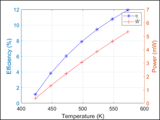
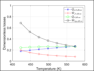
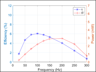
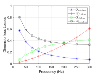
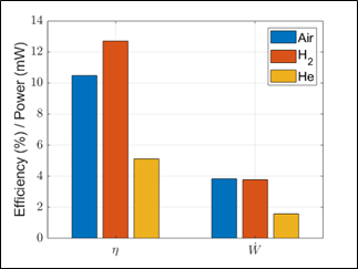
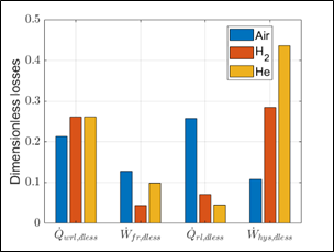
On the considered hot source temperature range 373 K-573 K, the machine delivered power raises from 0.4 to 5.4 mW (Figure 6). Therefore, the power density per cm2 of heated surface varies from 1.8 mW.cm-2 to 27.2 mW.cm-2. The increase in the efficiency is limited by the increase in regenerator conduction and inefficiency losses (Figure 7) as the difference between the cold source temperature and hot sink temperature increases (Eq. (13);(19)). Hysteresis and friction dimensionless losses decrease as the power of the machine raises with temperature. The evolution of efficiency and delivered power with frequency (Figure 8) presents a raise, then a maximum at 100 and 200 Hz respectively, and a decrease for both curves. Therefore, maximal efficiency and maximal power are not observed at the same operating point. The observation of the main losses (Figure 9) reveals that as frequency raises, the losses due to pressure drops, that are mainly due to the regenerator, sharply raise. Moreover, the losses due to inefficiency of the regenerator also raise. Therefore, the engine miniaturization does not lead to a large increase in the optimal operational frequency compared to macroscopic engines that operate at about 50 Hz, and this is mainly due to thermofluidic losses. Finally, we studied the influence of helium and hydrogen as working gases. Helium is a frequent working gas for macroscopic engines due to its high thermal conductivity. Hydrogen properties are also interesting and miniature engines need a small mass of gas, therefore hydrogen security aspects can be easier to handle. As explained in the preceding paragraph, hydrogen and helium lead to high hysteresis losses if the bounce space volume is too low. At a ratio of 20%, the hysteresis losses amount to 8.8 mW and 5.7 mW for helium and hydrogen respectively and would be dissipating more than the adiabatic power. Therefore, to compare these gases with air, we use a design where the bounce space volume variation is 5%. The efficiency and power for the three gases are plotted in Figure 10. Hydrogen appears to be the better choice, with a higher efficiency and an equivalent power compared to a dry air engine. Air engine efficiency is reduced by high regenerator efficiency losses (Figure 11). Helium is the worst choice due to high hysteresis and friction losses that have a strong impact on the power.
Figure 6. Variation of efficiency and power with temperature
Figure 7. Variation of losses with temperature
Figure 8. Variation of efficiency and power with frequency
Figure 9. Variation of main losses with frequency
Figure 10. Variation of efficiency, power, heat in and main losses with the working gas
4.3.2 Influence of geometric parameters: regenerator length and porosity, bounce space volume
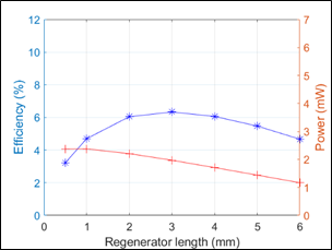
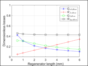
Geometric parameters that may have an influence on the main losses mainly concern the regenerator as the regenerator inefficiency and conduction losses are the first two main losses of the base design model (Table 2). The efficiency variation with the regenerator length (Figure 12) presents a raise, a maximum at 3 mm, then decreases. The observation of the losses (Figure 13) shows that a short regenerator leads to high thermal inefficiency and high conduction losses. Indeed, a short regenerator does not enable all heat exchange between the gas and the regenerator pillars to take place during the cycle. The conduction losses increase as the regenerator wall thermal conductance is inversely proportional to the regenerator length. On the other hand, the higher length values lead to an increase in the friction losses. These phenomenon account for the bell shape or the efficiency curve (Eq. (39)).
Figure 11. Variation of main losses with the working gas
Figure 12. Variation of efficiency and power with regenerator length
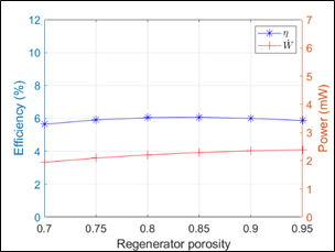
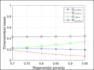
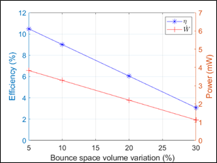
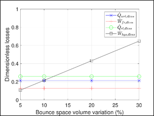
The same analysis was made with the variation of the regenerator porosity. For a 2 mm-long regenerator, the efficiency is nearly constant over a porosity range of 0.7 to 0.9 (Figure 14). On this range, the power slightly raises. The observation of the main losses (Figure 15) shows that the regenerator thermal efficiency losses raise when the porosity is higher but on the other hand friction losses decrease. This accounts for the shape of the efficiency curve. Hysteresis losses in the bounce space are also one of the major losses (Table 2). They depend on the bounce space volume relative variation (Eq. (31)). So, they greatly contribute to the overall losses if this volume variation is high. Therefore, in macroscopic engines, the bounce space is usually designed large. However, this can be difficult at micro-scale level, as the aim is to have a miniature machine. Therefore, we studied the efficiency and power of the engine with the bounce space volume variation (Figure 16). Clearly, a large bounce space volume leading to small relative variations during the cycle is beneficial. We observe that, for the base design using air as working gas, the hysteresis losses overcome the pressure drop losses for a volume variation of 6% (Figure 17). This ratio is also a key parameter when using hydrogen or helium as working gases in the engine due the high values of specific heat ratio of and conductivity for these gases.
4.3.4 Design guidelines
As a summary of the parametric study, we can derive the following thermal design guidelines appropriate for a miniaturized engine with millimetric size:
• regenerator design is, as in macroscopic engines, a key point in the performance,
• regenerator wall thickness should be minimized due to the impact of conduction losses at low swept volumes,
• bounce space volume need to be carefully optimized due to the impact of hysteresis losses,
• hydrogen is a good choice as a working gas, air is second choice and helium is not a good choice if the bounce space is not purposefully designed,
• the raise in frequency expected for micro-scale devices is limited by thermofluidic losses,
• squeeze film damping and finite speed losses can be neglected.
Figure 13. Variation of main losses with regenerator length
Figure 14. Variation of efficiency and power with regenerator porosity
Figure 15. Variation of main losses with regenerator porosity
Figure 16. Variation of efficiency and power with bounce space
Figure 17. Variation of main losses with bounce space volume variation
In this paper, we have proposed a new model and design of a MEMS miniaturized Stirling engine. This engine could be used to locally provide electric power to systems of low energy demand. A modified adiabatic model including losses such as regenerator thermal efficiency, wall conduction, pressure drop, hysteresis, membrane finite speed and squeeze film damping losses was developed. A base design machine was proposed, a parametric study was conducted and used to derive guidelines for miniature design. Compared to macro-scale design, the same trend was observed for the influence of the thermal performance regenerator. However, different trends from macroscopic engines were observed: conduction losses are of major importance due to the low power of the miniature engines, hysteresis losses in the bounce space are also of high amplitude due to the small size if this volume, the choice of the working gas leads to hydrogen or air and not helium. The raise in frequency expected for micro-scale devices is limited by thermofluidic losses. Squeeze film damping and finite speed losses can be neglected at this scale.
This work has been supported by the EIPHI GraduateSchool (contract ANR-17-EURE-0002) and the Region Bourgogne-Franche-Comté.
|
A |
free flow area, m2 |
|
Aw |
wall area, m2 |
|
Awg |
wetted area, m2 |
|
c |
average molecular speed, m.s−1 |
|
Cp |
isobaric specific heat, J.kg−1.K−1 |
|
Cv |
isochoric specific heat, J.kg−1.K−1 |
|
D |
squeeze film damping coefficient, kg.s−1 |
|
d |
diameter, m |
|
fr |
dimensionless Fanning friction factor |
|
Fsf |
squeeze film damping force, N |
|
h |
heat transfer coefficient, W.m−2.K−1 |
|
k |
thermal conductivity, W.m−1.K−1 |
|
KD |
dimensionless minor loss coefficient for sudden compression or expansion |
|
L |
length, m |
|
m |
mass of working fluid, kg |
|
NTU |
Number of Transfer Units |
|
Nu |
Nusselt number |
|
P |
pressure, Pa |
|
Pr |
Prandtl number |
|
Q |
heat, J |
|
Qrl |
regenerator heat losses, J |
|
Qwrl |
regenerator wall conduction losses, J |
|
r |
radius, m |
|
Re |
Reynolds number |
|
s |
stroke, m |
|
St |
Stanton number |
|
T |
temperature, K |
|
V |
volume, m3 |
|
v |
velocity, ms−1 |
|
Vb |
bounce space volume, m3 |
|
Vc |
compression space volume, m3 |
|
Ve |
expansion space volume, m3 |
|
Vswc |
compression space swept volume, m3 |
|
Vswe |
expansion space swept volume, m3 |
|
W |
work, J |
|
Wfr |
pressure drop losses, J |
|
Wfs |
membrane finite speed losses, J |
|
Whys |
hysteresis losses, J |
|
Wsf |
squeeze film damping losses, J |
|
z |
chamber height, m |
|
Greek symbols |
|
|
γ |
specific heat ratio |
|
η |
efficiency |
|
ψ |
dimensionless regenerator porosity |
|
σ |
squeeze number |
|
ω |
angular speed, rad.s−1 |
|
Subscripts |
|
|
ad |
adiabatic |
|
b |
bounce space |
|
c |
compression space |
|
e |
expansion space |
|
g |
gas |
|
H |
hydraulic |
|
h |
hot heat exchanger |
|
in |
inlet |
|
k |
cold heat exchanger |
|
m |
membrane |
|
r |
regenerator |
|
t |
total |
|
w |
wall |
[1] Chen, G., Hanson, S., Blaauw, D., Sylvester, D. (2010). Circuit design advances for wireless sensing applications. Proceedings of the IEEE, 98(11): 1808-1827. https://doi.org/10.1109/JPROC.2010.2053333
[2] Papapetrou, M., Kosmadakis, G., Cipollina, A., La Commare, U., Micale, G. (2018). Industrial waste heat: Estimation of the technically available resource in the EU per industrial sector, temperature level and country. Applied Thermal Engineering, 138: 207-216. https://doi.org/10.1016/j.applthermaleng.2018.04.043
[3] Walker, G. (1980). Stirling Engines. Oxford University Press, New York.
[4] Bataineh, K., Taamneh, Y. (2017). Performance analysis of stand-alone solar dish stirling system for electricity generation. International Journal of Heat and Technology, 35(3): 498-508. https://doi.org/10.18280/ijht.350306
[5] Ceruti, A. (2013). Design and heuristic optimization of low temperature differential stirling engine for water pumping. International Journal of Heat and Technology, 31(1): 9-16. https://doi.org/10.18280/ijht.310102
[6] Tlili, I. (2012). Numerical investigation of an alpha stirling engine using the ross yoke linkage. International Journal of Heat and Technology, 30(1): 23-36. https://doi.org/10.18280/ijht.300104
[7] Thombare, D.G., Verma, S.K. (2008). Technological development in the Stirling cycle engines. Renewable and Sustainable Energy Reviews, 12(1): 1-38. https://doi.org/10.1016/j.rser.2006.07.001
[8] Nakajima, N., Ogawa, K., Fujimasa, I. (1989). Study on microengines: Miniaturing Stirling engines for actuators. Sensors and Actuators, 20(1-2): 75-82. https://doi.org/10.1016/0250-6874(89)87104-5
[9] Moran, M.E. (2002). U.S. Patent No. 6,385,973. Washington, DC: U.S. Patent and Trademark Office. US6385973 B1.
[10] Moran, M., Wesolek, D., Berhane, B., Rebello, K. (2004). Microsystem cooler development. In 2nd International Energy Conversion Engineering Conference, 5611. https://doi.org/10.2514/6.2004-5611
[11] Formosa, F., Fréchette, L.G. (2015). Multi-physics modelling approach for oscillatory microengines: application for a microStirling generator design. In Journal of Physics: Conference Series, 660(1): 012071. https://doi.org/10.1088/1742-6596/660/1/012071
[12] Madou, M.J. (2002). Fundamentals of Microfabrication: The Science of Miniaturization. CRC Press. ISBN: 0-8493-0826-7
[13] Diallo, A.D. (2019). Contribution to the design and fabrication of a Stirling cycle thermal micromachine with stirling cycle. PhD of University Bourgogne Franche-Comté.
[14] Diallo, A., Chutani, R., Barthès, M., Bégot, S., Khadraoui, S., De Labachelerie, M., Lanzetta, F. (2018). Study of dynamic response of silicone elastomer microfabricated Hybrid Membranes versus temperatures and aging time. In Journal of Physics: Conference Series, 1052(1): 012036. https://doi.org/10.1088/1742-6596/1052/1/012036
[15] Dellali, E., Bégot, S., Lanzetta, F., Gavignet, E., Chutani, R.K., Rauch, J.Y. (2016). Design, fabrication and CFD modeling of a Stirling engine microregenerator. In 17th International Stirling Engine Conference and Exhibition, 24th-26th August, Northumbria Univesity, Newcastle upon Tyne, UK, pp. 190-200.
[16] Urieli, I., Berchowitz, D.M. (1984). Stirling Cycle Engine Analysis. Bristol: Adam Hilger.
[17] Thieme, L.G., Tew Jr, R.C. (1978). Baseline performance of the GPU 3 Stirling engine. In Highway Vehicle Systems Contractors Coordination Meeting.
[18] Costea, M., Petrescu, S., Harman, C. (1999). The effect of irreversibilities on solar Stirling engine cycle performance. Energy Conversion and Management, 40(15-16): 1723-1731. https://doi.org/10.1016/S0196-8904(99)00065-5
[19] Timoumi, Y., Tlili, I., Nasrallah, S.B. (2008). Design and performance optimization of GPU-3 Stirling engines. Energy, 33(7): 1100-1114. https://doi.org/10.1016/j.energy.2008.02.005
[20] Bao, M. (2005). Analysis and design principles of MEMS devices. Elsevier. https://doi.org/10.1016/B978-0-444-51616-9.X5000-0
[21] Vanapalli, S., ter Brake, H.J., Jansen, H.V., Burger, J. F., Holland, H.J., Veenstra, T.T., Elwenspoek, M.C. (2007). Pressure drops of laminar gas flows in a microchannel containing various pillar matrices. Journal of Micromechanics and Microengineering, 17(7): 1381. https://doi.org/10.1088/0960-1317/17/7/021
[22] Hosseinzade, H., Sayyaadi, H. (2015). CAFS: The Combined Adiabatic–Finite Speed thermal model for simulation and optimization of Stirling engines. Energy conversion and Management, 91: 32-53. https://doi.org/10.1016/j.enconman.2014.11.049
[23] Bao, M., Yang, H. (2007). Squeeze film air damping in MEMS. Sensors and Actuators A: Physical, 136(1): 3-27. https://doi.org/10.1016/j.sna.2007.01.008