Fei Zhao | Xiaowei Li* | Jiangli Hou
© 2021 IIETA. This article is published by IIETA and is licensed under the CC BY 4.0 license (http://creativecommons.org/licenses/by/4.0/).
OPEN ACCESS
The research on the vehicle thermal management (VTM) system is very important for ensuring the driving reliability of electric cars, however, currently there’re few research concerned about this topic, and the existing ones mostly focus on matching and optimizing parameters to improve the management of driving kinetic energy, and the heat dissipation and cooling performance of the cars; however, there isn’t a uniform standard for evaluating these performances, and the research on closed thermal energy management and control based on the evaluation results is pending. This paper studied the simulation and multi-objective optimization of the VTM system of electric cars, and proposed accurate methods and ideas for evaluating the heat dissipation efficiency of the engine cooling system, the cooling efficiency of the air conditioning system, and the thermal management performance of the VTM of electric cars. Based on the model predictive control (MPC) algorithm of vehicle motion control, this paper constructed temperature control optimization objective functions for electric cars under various thermal adaptation working conditions such as low-speed slope climbing, medium-speed gentle slope climbing, high-speed driving, and idling; and it designed several strategies for the coordinated control of the VTM system of electric cars. At last, this paper used test results to verify the effectiveness of the proposed strategies.
electric cars, vehicle thermal management (VTM), system simulation, multi-objective optimization
As electric cars are developing at an astonishing speed, the heat flux density of the engine is increasing, and faults related to the thermal management system are on the rise [1-5]. Studies on the engine cooling system, engine lubrication system, power transmission system, air conditioning system and other subsystems are of great practical significance for ensuring the driving reliability of electric cars [6-10].
The difference of the research on the thermal management of traditional cars and electric cars lies in that the former targets at engine cooling, while the latter focuses on the temperature field of power batteries [11-16]. Docimo et al. [17] took hybrid light-duty trucks as the research object, they paid special attention to the driving mode characteristics of trucks and the temperature of the entire vehicle, and designed a VTM system with preheating and heat dissipation functions. Based on the driving mode features of electric cars, Smith et al. [18] analyzed the parameters and thermal requirements of various power components and proposed a set of designs for engine cooling, engine preheating, and battery preheating; combining with the parameters of the cooling system and air-conditioning system in the VTM system, they further obtained the quantified value of the temperature control objective based on human body comfort. Garrow et al. [19] used MATLAB to simulate the power control and thermal management processes of hybrid electric cars, and compared the simulation results of the engine cooling system, power transmission system, air conditioning system, and lubrication system with their test data. Schaut and Sawodny [20] used Amesim and Cruise to analyze the parameter sensitivity of a constructed VTM simulation model, and explored the impact of several parameters on the fuel consumption and exhaust emissions of the vehicle under comprehensive driving cycle working conditions. Wiriyasart et al. [21] constructed a VTM objective function with economy and low carbon performance as the objectives and designed heat dissipation constraints, after DOE test, they obtained a parameter configuration scheme that can reasonably reduce the fuel costs. Fu et al. [22] gave the structure of the power system and thermal management system of electric cars based on APU coordinated control, calculated the real-time heat load, match the parameters of the cooling system, and perform simulation tests to verify the feasibility of APU operating point selection based on the power balance equation.
The simulation analysis of the VTM system of electric cars involves the knowledge of multiple subjects and disciplines, and it emphasizes on the coupling and mutual impact of the sub-systems contained in it; now there’s few research concerned about it, the existing studies mostly focus on matching and optimizing the parameters to improve the management of kinetic energy of the driving force and the heat dissipation and cooling performance [23-27], however, in these studies, the evaluation criteria of the performance are not uniform, and the research on closed thermal energy management and control based on the evaluation results is pending. The second chapter of this paper accurately evaluated the heat dissipation efficiency of the engine cooling system and the cooling efficiency of the air conditioning system of electric cars. The third chapter proposed a few evaluation ideas for the thermal management performance of the VTM system of electric cars. The fourth chapter constructed temperature control optimization objective functions for electric cars under various thermal adaptation working conditions based on the model predictive control (MPC) algorithm of vehicle motion control, and further designed several strategies for the coordinated control of the VTM system of electric cars. At last, this paper used test results to verify the effectiveness of the proposed strategies.
In order to get accurate evaluation results of the heat dissipation efficiency of the engine cooling system and the cooling efficiency of the air conditioning system of electric cars, this study collected the real-time data of the temperature of the coolant at the engine outlet, the collected results and the maximum working environment temperature of the engine were taken as the indicators to evaluate the heat dissipation efficiency; moreover, the data of the average temperature inside the car were also collected in real time, and the collected results and the cooling cycle were taken as the indicators to evaluate the cooling efficiency.
Suppose: ECS represents the engine cooling system; function ξAM represents the mapping between ψE (the temperature of coolant at engine outlet) and ψSU (the ambient temperature). Referring to the working status parameters of the thermal adaption of engine cooling system listed in Table 1, under the condition that the thermal adaption working status has already been determined (including low-speed climbing, medium-speed climbing, high-speed driving, and idling), the single-valued mapping between ψE and ψSU can be expressed as Formula 1:
${{\psi }_{E}}={{\xi }_{AM}}\left( {{\psi }_{SU}} \right)$ (1)
Suppose: ψSU-max and ψSU-D represent the maximum working environment temperature of the engine and the design value of the working environment temperature; ψE-BP represents the boiling point temperature of the coolant, then there is:
$\psi_{S U-\max }=\frac{1}{\xi_{A M} \quad \left(\psi_{E-B P}\quad\right)} \geq \psi_{S U-D}$ (2)
Table 1. Working status parameters of the thermal adaptation of engine cooling system
|
Working status |
Idling start |
Low speed |
Medium speed |
High speed |
|
Parameter |
The car is started but the engine doesn’t do work |
12% slope Car speed 60km/h 65% rated rotate speed |
8% slope Car speed 100km/h 75% rated rotate speed |
Flat ground Car speed 130km/h 86% rated rotate speed |
According to the design and manufacturing requirements of pure electric cars or hybrid electric cars, under the condition that the air conditioning system is running, the design value of the working environment temperature of the engine ψSU-D should be higher than 40℃. Based on the relationship between the temperature of coolant at the engine outlet ψE and the maximum working environment temperature ψSU-max shown as Formulas 1 and 2, the heat dissipation efficiency of the engine cooling system of the electric cars could be evaluated and analyzed using two methods, the checking evaluation method, and the estimation evaluation method.
In the checking evaluation, at first, it’s assumed that ψE-D represents the temperature of coolant at the engine outlet ψE under the condition that the design value of the working environment temperature of the engine ψSU-D is determined; ψE-M represents the remain coolant of the system; if ψE-M is less than 0, then it indicates that ψE is higher than the boiling point under the condition that ψSU-D is determined, and it means that there’s still a gap between the cooling performance of the engine cooling system and the design requirements. By bringing ψSU-D into Formula 1, the calculation of ψE-D could be completed:
${{\psi }_{E-D}}={{\xi }_{AM}}\left( {{\psi }_{SU-D}} \right),{{\psi }_{E-M}}={{\psi }_{E-BP}}-{{\psi }_{E-D}}$ (3)
The estimation evaluation is an indirect method for estimating the maximum working environment temperature ψSU-max based on the temperature of coolant at the engine outlet ψE-EX and the test environment temperature ψSU-EX, under the test conditions, the relationship between ψE-EX and ψSU-EX can be described by Formula 4 as:
$\psi_{S U-E X}=\frac{1}{\xi_{A M} \quad \left(\psi_{E-E X} \quad\right)}$ (4)
when the valve that controls the coolant flow path opens to the maximum extent, 1/ξAM(*) can be regarded as a linear function. Suppose δAM represents the linear proportional coefficient corresponding to the maximum opening degree of the coolant flow path control valve, by combining Formula 2 with Formula 4, there is:
${{\psi }_{SU-max}}={{\delta }_{AM}}\cdot \left( {{\psi }_{E-BP}}-{{\psi }_{E-EX}} \right)+{{\psi }_{SU-EX}}$ (5)
Suppose δEX represents the cooling constant of the engine cooling system, then, by further simplifying above formula, there is:
$\begin{align} & {{\psi }_{SU-max}}={{\psi }_{E-BP}}-\left( {{\psi }_{E-EX}}-{{\psi }_{SU-EX}} \right) \\ & ={{\psi }_{E-BP}}-{{\delta }_{EX}} \\\end{align}$ (6)
Since higher δEX value means lower ψSU-max value, essentially, the checking evaluation method corresponds to Formula 1, and the estimation evaluation method corresponds to Formula 2, to some point, the two methods are equivalent, and can be transformed into each other.
Suppose: ACS represents the air conditioning system; function ξPO represents the mapping between ψCC (temperature inside the car) and ψSU (ambient temperature); similarly, referring to the working status parameters of the thermal adaption of the air conditioning system listed in Table 2, under the condition that the thermal adaption working status has already been determined, the single-valued mapping between ψCC and ψSU can be expressed by Formula 7:
${{\psi }_{CC}}={{\xi }_{PO}}\left( {{\psi }_{SU}} \right)$ (7)
Suppose: ψCC-D represents the design value of the temperature inside the car; according to the manufacturer’s design requirements for the cooling performance of the air-conditioning system and the design and manufacturing requirements of pure electric cars or hybrid electric cars, the premise for that the average temperature inside the car is lower than the design value of human body comfort requirement is that ψSU is higher than 38°C, by bringing ψSU-EX into the above formula, there is:
${{\psi }_{CC}}\le {{\psi }_{CC-D}}={{\xi }_{AC}}\left( {{\psi }_{SU-D}} \right)$ (8)
Suppose: PC represents the power of the air conditioner compressor calculated based on PC-IP (the indicated power of the air conditioner compressor) and λC (the efficiency of the air conditioner compressor), then, for per unit power consumption of the air conditioner compressor, the cooling capacity of the evaporator could be defined as ARC, namely the cooling cycle of the air-conditioning system of electric cars, then there is:
$ARC=\frac{{{{\dot{W}}}_{E}}}{{{P}_{C}}}$ (9)
Table 2. Working status parameters of the thermal adaption of the air-conditioning system
|
Working status |
Idling start |
Low speed |
Medium speed |
High speed |
|
Parameter |
The car is started but the engine doesn’t do work |
Flat ground Car speed 50km/h, 60% rated rotate speed |
Flat ground Car speed 90km/h, 70% rated rotate speed |
Flat ground Car speed 120km/h, 80% rated rotate speed |
Suppose: λC-IS represents the isentropic compression efficiency of the air conditioner compressor; λC-ME and λC-VO represent the mechanical efficiency and volumetric efficiency of the air conditioner compressor; λC-IS represents the non-isentropic compression loss of gas that is actually compressed; λC-ME represents the mechanical friction loss of the air conditioner compressor components; λC-VO represents the coolant charge loss of the air conditioner; Formula 10 gives the formula for calculating PC-IP, the indicated power of the air conditioner compressor:
${{P}_{C-IP}}={{P}_{C}}\cdot {{\lambda }_{C}}={{P}_{C}}\cdot {{\lambda }_{C-VO}}\cdot {{\lambda }_{C-IS}}\cdot {{\lambda }_{C-ME}}$ (10)
According to above formula, the rotate speed of the air conditioner compressor has a quadratic relationship with λC-ME and PC-IP, and it has a monotonically decreasing linear relationship with mechanical efficiency. Suppose GAO and GAI represent the actual outlet specific enthalpy and actual inlet specific enthalpy of the compressor; GAI-IS represents the GAI that is calculated based on the isentropic compression process, then, the calculation of λC-IS could be completed by calculating the ratio of the isentropic compression enthalpy increment of the coolant to the actual compression enthalpy increment, as shown in Formula 11:
${{\lambda }_{C-IS}}=\frac{{{G}_{AI-IS}}\quad-{{G}_{AO}}}{{{G}_{AI}}-\quad{{G}_{AO}}}$ (11)
Based on the compression cycle theory, the air intake process work, the air outtake process work, and the air compression work of the air conditioner compressor could be superimposed, and their sum is the indicator work of the air conditioner compressor. Suppose Smax and Smin represent the maximum stroke volume and minimum stroke volume of the compressor, let their difference satisfy:
${{S}_{C}}={{S}_{max}}-{{S}_{min}}$ (12)
The indicated power of the air conditioner compressor satisfies:
$\begin{align} & \frac{{{P}_{C-IP}}}{{{M}_{C}}/60}={{E}_{AO}}\cdot {{S}_{max}}-{{E}_{AI}}\cdot {{S}_{min}} \\ & +\int_{{{S}_{max}}}^{{{S}_{min}}}{E\cdot dS}=-\int_{{{E}_{AO}}}^{{{E}_{AI}}}{S\cdot dE} \\\end{align}$ (13)
Suppose βadi represents the adiabatic index of the coolant, then PC-IP could be calculated according to the isentropic compression process:
$\begin{align} & {{P}_{C-IP}}=-\int_{{{E}_{AO}}}^{{{E}_{AI}}}{S\cdot dE}\cdot {{M}_{C}} \\ & =-{{E}_{AO}}\cdot \left( {{S}_{max}}-{{S}_{min}} \right) \\ & \cdot \frac{{{\beta }_{adi}}}{{{\beta }_{adi}}-1}\left[ {{\left( \frac{{{E}_{AI}}}{{{E}_{AO}}} \right)}^{\frac{{{\beta }_{adi}}}{{{\beta }_{adi}}-1}}}-1 \right]\cdot {{M}_{C}} \\\end{align}$ (14)
In order to accurately evaluate the thermal management and control performance of the VTM system of electric cars, this paper calculated the error between the temperature control objective value that is used to measure the temperature stability of the VTM system and the actual output temperature. Suppose ψST-i represents the actual temperature at time moment i; ψST-C represents the temperature control objective value; EMS and EMA represent the mean square error and mean absolute error between ψST-i and ψST-C; ME represents the control time domain of the VTM system; ψmin and ψmax represent the minimum and maximum temperature in ME; then EMS could be calculated by Formula 15:
${{E}_{MS}}=\sqrt{\frac{1}{{{M}_{E}}}\cdot \sum\limits_{i=0}^{{{M}_{E}}}{{{\left( {{\psi }_{ST-i}}-{{\psi }_{ST-C}} \right)}^{2}}}}$ (15)
EMA could be calculated by Formula 16:
${{E}_{MA}}=\frac{1}{{{M}_{E}}}\sum\limits_{i=0}^{{{M}_{E}}}{\left| {{\psi }_{ST-i}}-{{\psi }_{ST-C}} \right|}$ (16)
ψST-i satisfies:
${{\psi }_{min}}\le {{\psi }_{ST-i}}\le {{\psi }_{max}}$ (17)
ψmin and ψmax could be respectively calculated by Formula 18 and Formula 19:
${{\psi }_{min}}=min\left( {{\psi }_{ST-i}}\left| i=0,1,2...{{M}_{E}} \right. \right)$ (18)
${{\psi }_{max}}=max\left( {{\psi }_{ST-i}}\left| i=0,1,2...{{M}_{E}} \right. \right)$ (19)
EMS and EMA respectively measure the precision and accuracy between the output temperature of the VTM system and the temperature control objective; ψmin and ψmax determine the fluctuation range of the actual output temperature, to a certain extent, they can reflect the degree of dispersion between the output temperature and the temperature control objective.
The energy consumption of the engine cooling system is mainly the energy consumption of the water pump and the fan. Suppose PWP-IP represents the indicated power of the water pump; PWP represents the power of the water pump; SWP represents the volume of the water pump; λWP represents the efficiency of the water pump; LWP represents the lift of the water pump; then, the actual power and indicated power of the water pump PWP and λWP could be calculated as:
$\begin{align} & {{P}_{WP-IP}}={{P}_{WP}}\cdot {{\lambda }_{WP}} \\ & ={{\sigma }_{E}}\cdot g\cdot {{L}_{WP}}\cdot {{S}_{WP}}\cdot {{M}_{WP}}/60 \\\end{align}$ (20)
In calculation process of PWP-IP, it is necessary to comprehensively consider the volume, and the hydraulic and mechanical friction losses related to the pump rotate speed and the inlet and outlet pressure. In order to obtain ideal lift and flow of the water pump, the valve that controls the flow path of the coolant that can adjust the flow rate of the circulating coolant could be used to control the energy consumption of the water pump.
Suppose PF-IP represents the indicated power of the fan, PF represents the power of the fan; λF represents the efficiency of the fan; μF represents air flow passing through the fan; ΔVRF represents the inlet and outlet pressure increment of the fan; the energy consumption analysis of the fan is similar to that of the water pump, then, the actual power and indicated power of the fan PF and λF could be calculated as:
${{P}_{F-IP}}={{P}_{F}}\cdot {{\lambda }_{F}}={{\dot{\mu }}_{F}}\cdot \Delta V{{R}_{F}}/60$ (21)
Under the condition that the structural features of the power compartment and the flow resistance features of the integrated heat exchanger of the electric car are fixed, then the inlet and outlet pressure increment of the fan inside the compartment, and the flow and rotate speed of the fan, are closely related to the driving speed of the car. It can be approximately considered that the flow resistance of the integrated heat exchanger has a quadratic relationship with its flow, and the flow of the integrated heat exchanger has a simple linear relationship with the rotate speed of the fan. Suppose o1, o2, and o3 represent the fitting coefficients of the cubic polynomial, then the indicated power of the fan could be fitted and calculated by Formula 22 as:
${{P}_{F-IP}}={{o}_{1}}\cdot P_{F}^{3}+{{o}_{2}}\cdot P_{F}^{2}+{{o}_{3}}\cdot {{M}_{F}}$ (22)
With the MPC algorithm of vehicle motion control as an example, this paper focused on the control objectives of the VTM system with higher priority, and constructed temperature control optimization objective functions for the thermal adaption working status of electric cars such as low-speed climbing, medium-speed climbing, high-speed driving, and idling; further, this paper designed a few strategies for the coordinated control of the VTM system of electric cars under these working status. Table 3 gives the basis for judging the priority of the control objectives of the VTM system.
Table 3. Basis for judging the priority of the control objectives of the VTM system
|
Working status Ambient temperature |
Start and stop under idling status |
Normal driving status |
Hot shutdown |
|
|
Driving under normal power status |
Driving under low-cost status |
|||
|
High temperature |
ECS is lower than ACS |
ACS is lower than ECS |
ACS\ECS both |
ECS |
|
Normal temperature |
ECS is lower than ACS |
ACS is lower than ECS |
ACS\ECS both |
ECS |
|
Low temperature |
ECS |
ECS |
ECS |
ECS |
Under normal and high temperature conditions, for the idling start-stop working status, the first thing is to ensure the cooling performance of the air conditioning system that cooperates with the condenser to dissipate heat. The compressor exhaust volume and the fan rotate speed can be defined as the core control variables of the system under normal and high temperature conditions; and the cooling duration εadi of the air conditioning system can be defined as the control objective of this working status. Figure 1 gives the design requirements for cooling performance of the air conditioning system under normal and high temperature conditions. To ensure that the cooling duration of the air conditioning system has a unique minimum value, the system energy consumption constraint needs to be introduced, Formula 23 gives the control objective optimization function of this working status:
$\begin{align} & OF=O{{F}_{\varepsilon -adi}}+O{{F}_{P}} \\ & =\left( {{\beta }_{adi}}\cdot {{\varepsilon }_{adi}}\cdot {{q}_{adi}} \right)+\sum\limits_{i=0}^{{{\varepsilon }_{adi}}/\Delta \varepsilon }{{{P}_{T}}}\cdot \Delta \varepsilon \\\end{align}$ (23)
Figure 1. Design requirements for cooling performance of the air conditioning system under normal and high temperature conditions
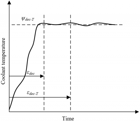
According to above formula, εadi is a function of SC and MF. When εadi is less than εadi-T, OFε-adi is equal to 0, βadi is greater than ∑(PT-max∙∆ε)/εadi-T, qadi=-βadi∙εadi-T. Since the compressor and the cooling fan are the main actuators of the VTM system under normal and high temperature conditions, PT is equal to PSU+PF. The above analysis is only applicable to normal and high temperature working conditions; for the idling start-stop under low temperature working conditions, the first thing is to ensure the warm-up capability of the engine; at this time, the air conditioning system, the cooling fan, and that valve that controls the coolant flow path are all closed, the rotate speed of the water pump could be defined as the core control variable under the low-temperature working condition, and the engine warm-up duration εdec could be defined as the control objective of this working status. Figure 2 gives the design requirements for the engine warm-up performance under low temperature working conditions, and Formula (24) gives the control objective optimization function of this working status:
$O F=O F_{\varepsilon-d e c}+O F_{P}$
$=\left(\beta_{d e c} \cdot \varepsilon_{d e c} \cdot q_{d e c}\right)+\sum_{i=0}^{\varepsilon_{d k c-T} \quad/ \Delta \varepsilon} P_{T} \cdot \Delta \varepsilon$ (24)
where, εdec is a function of MWP. When εdec is less than εdec-T, OFε-dec is equal to 0, βdec is greater than ∑(PT-max∙∆ε)/εdec-T, and qwar is equal to -βdec ∙εdec-T. Under low temperature working conditions, the only main actuator of the VTM system is the water pump, so PT is equal to PWP.
When an electric car is under normal driving status, it’s required that the output power of the engine should meet the power requirements of the car to move forward, and at the same time, it’s necessary to ensure that the boiling point temperature is lower than the coolant temperature, and it’s quite important to guarantee the efficiency of the cooling system. The water pump and the fan rotate speed could be defined as the control output of the VTM system, and the engine output power and coolant temperature could be defined as the control objectives of the system. However, in the actual design process of the thermal management of electric cars, more attention should be paid to the driving reliability of the car, the boiling point temperature won’t be directly taken as the reference water temperature, instead of the boiling point temperature, the temperature value below a certain boiling point temperature that ensures certain system remain coolant was taken to define the temperature control objective of the coolant, that is, ψE-adi is equal to ψE-BP-ψE-M (ψE-M is greater than ψE-MA).
Figure 2. Design requirements for engine warm-up performance under low temperature working condition
This study chose to control the output power of the engine by controlling the temperature of the engine block. Under the condition that thermal management and power management of the electric car are both in a balanced state and the opening degree of the accelerator pedal is fixed, the temperature of the engine coolant and the temperature of the engine block together determine the output power of the engine. If the engine coolant temperature is controlled near the value of ψE-adi, then the output power EEO is equal to hEO(ψP|ψE-ψE-adi). The temperature control objective of the VTM system could be defined as that engine block temperature under the condition that the engine output power satisfies the power requirement of the car to more forward, then, ψE-adi is equal to h-1EO(EEO-T|(ψE-ψE-adi).
To effectively reduce the thermal management cost of the car under high temperature conditions, the control requirements of the air-conditioning system and the engine cooling system need to be considered comprehensively, that is, PT is equal to PEO+PF. The rotate speed of the water pump, the rotate speed of the fan, and the exhaust volume of the air conditioner compressor were determined as the control output of the VTM system; the temperature inside the car, the temperature of the engine coolant, the energy consumption of the engine cooling system, and the energy consumption of the air conditioning system were defined as the temperature control objectives of the VTM system, Figure 25 gives the control objective optimization function of this working status:
$\begin{align} & OF=O{{F}_{{{\psi }_{E}}}}+O{{F}_{{{\psi }_{CC}}}}+O{{F}_{P}} \\ & =\sum\limits_{i=\beta }^{\beta +o}{\left( {{\beta }_{E}}\cdot {{\psi }_{E}}\left( i\left| \beta \right. \right)+{{q}_{E}} \right)} \\ & +\sum\limits_{i=\beta }^{\beta +o}{\left( {{\beta }_{CC}}\cdot {{\psi }_{CC}}\left( i\left| \beta \right. \right)+{{q}_{CC}} \right)} \\ & +\sum\limits_{i=\beta }^{\beta +o}{{{P}_{T}}\left( i\left| \beta \right. \right)}\cdot \Delta \varepsilon \\\end{align}$ (25)
when ψE is less than ψE-adi, OFψE is equal to 0; when ψCC is less than ψCC-adi, OFψCC is equal to 0. βE is greater than (∑PT-max∙Δε)/ψE-adi∙qE, namely -βE∙ψE-adi, and βCC is greater than (∑PT-max∙Δε)/βCC-adi∙qCC, namely -βCC∙ψCC-adi.
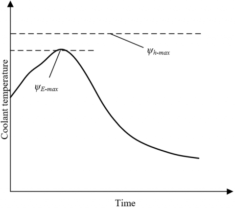
Figure 3. Design requirements for the lagging cooling performance of the engine
To avoid the occurrence of heat peaks, the hot shutdown working status needs to ensure that the engine has the lagging cooling function, the valve that controls the coolant flow path should be opened to the greatest extent, so that all coolant could enter the heat cycle of the radiator. Figure 3 shows the design requirements for the lagging cooling performance of the engine. The rotate speed of the water pump and the rotate speed of the fan were determined as the control variables of the VTM system, the engine coolant temperature was defined as the temperature control objective of the VTM system, Figure 26 gives the control objective optimization function of this working status:
$\begin{align} & OF={{J}_{{{\psi }_{h}}}}+{{J}_{P}} \\ & =\sum\limits_{i=\beta }^{\beta +o}{\left( {{\beta }_{E}}\cdot {{\psi }_{i}}\left( i\left| \beta =0 \right. \right)+{{q}_{h}} \right)} \\ & +\sum\limits_{i=\beta }^{\beta +o}{{{P}_{T}}}\cdot \Delta \varepsilon \\\end{align}$ (26)
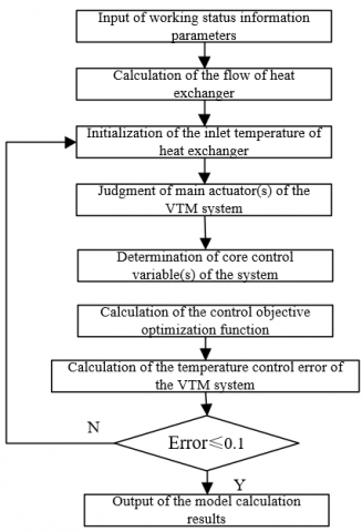
when ψE is less than ψh-max, OFψh is equal to 0, βh is less than -∑PT-max∙Δε/Tf-max, qh is equal to -βh∙ ψh-max; at this time, PT is equal to PWP+PF. Figure 4 shows the simulation process of the integrated VTM system of electric cars, which contains 8 steps: the input of working status information parameters; the calculation of the flow of heat exchanger; the initialization of the inlet temperature of heat exchanger, the judgment of main actuator(s) of the VTM system; the determination of core control variable(s) of the system; the calculation of the control objective optimization function; the calculation of the temperature control error of the VTM system; and the judgement of whether the error satisfies the preset requirement or not.
Figure 4. Simulation process of the integrated VTM system of electric cars
According to the process shown in Figure 4, the control objectives of the integrated VTM system of electric cars were simulated and calculated, and the results were compared with the road test results. Table 4 shows the simulation calculation results, and Table 5 shows the road test results.
Based on the existing confidence standards, the degree of confidence of the simulation calculation results of the engine cooling system and the air conditioning system was evaluated. Under the four thermal adaptation working conditions of idling start, low speed, medium speed and high speed, the degree of confidence of the simulation calculation results of the maximum working environment temperature and the average temperature inside the car were relatively ideal, and the errors were within the allowable range. These results were quite similar to the road test results listed in Table 4, and it’s highly scientific to apply them to the checking evaluation of parameters.
Table 4. Simulation calculation results
|
Working status |
Outlet water temperature of the engine |
Heat load of the engine |
Cooling capacity of the evaporator |
Heat dissipation of the condenser |
Maximum working environment temperature |
Error of the maximum working environment temperature |
Average temperature inside the car |
Error of the average temperature inside the car |
|
Idling start |
88.92 |
6.37 |
2.435 |
3.125 |
63.7 |
1.23 |
31.9 |
5.72 |
|
Low speed |
116.7 |
24.35 |
5.325 |
8.267 |
37.9 |
1.35 |
25.3 |
6.02 |
|
Medium speed |
103.1 |
32.64 |
5.903 |
8.672 |
48.9 |
1.74 |
22.6 |
5.72 |
|
High speed |
94.6 |
32.75 |
5.827 |
8.472 |
53.2 |
3.96 |
22.3 |
8.35 |
Table 5. Road test results
|
Working status |
Rotate speed of the engine |
Outlet water temperature of the engine |
Driving wheel power |
Slope |
Ambient temperature |
Rotate speed of the fan |
Maximum working environment temperature |
Average temperature inside the car |
|
Idling start |
854 |
89.2 |
0 |
0% |
36.8 |
3447 |
62.4 |
30.2 |
|
Low speed |
3521 |
116.7 |
17.9 |
10% |
35.2 |
3542 |
37.9 |
23.4 |
|
Medium speed |
3937 |
101.2 |
36.3 |
6.5% |
36.1 |
3579 |
51.3 |
20.5 |
|
High speed |
3729 |
91.8 |
37.1 |
0% |
35.4 |
3593 |
56.9 |
18.7 |
Table 6. Measurement and calculation results of the inlet temperature of heat exchanger
|
Type of the result |
Low speed slope climbing |
Medium speed gentle slope climbing |
High speed driving |
Idling |
|
|
Ambient temperature |
34.85 |
35.73 |
35.61 |
37.61 |
|
|
Condenser |
Simulation result |
11.36 |
2.12 |
0.97 |
16.72 |
|
Test result |
11.45 |
2.53 |
0.89 |
16.35 |
|
|
Relative error |
4.15 |
3.92 |
0.72 |
2.43 |
|
|
Radiator |
Simulation result |
18.92 |
6.87 |
5.38 |
22.45 |
|
Test result |
17.9 |
7.75 |
6.79 |
23.24 |
|
|
Relative error |
2.98 |
5.32 |
8.25 |
5.63 |
|
Table 7. Simulation calculation results of the engine cooling system under special working status
|
Calculation parameter |
Ambient temperature |
Rotate speed of the water pump |
Inlet temperature of the radiator |
Radiator coolant flow |
Out let water temperature of radiator |
Opening degree of valve |
Rotate speed of engine |
Heat load of engine |
Outlet water temperature of engine |
Remain coolant |
|
Equivalent load |
45 |
5312 |
53.25 |
135.72 |
106.31 |
99 |
3492 |
25600 |
109.95 |
5.80 |
|
Air conditioner doesn’t operate |
45 |
5291 |
53.42 |
136.71 |
103.21 |
98 |
3495 |
24105 |
106.25 |
9.72 |
|
Operate on test bench |
45 |
5312 |
42.08 |
115.36 |
87.92 |
87 |
3496 |
24105 |
94.30 |
23.05 |
Table 8. Factors affecting the temperature increment of the coolant and the proportion of temperature increment
|
Factors affecting the temperature increment of the coolant |
Upstream heating of the condenser |
Heat load of the energy consumption of the compressor |
High temperature reflux of the radiator |
|
|
Low speed |
Temperature increment of the coolant |
9.25 |
4.37 |
12.35 |
|
Proportion of temperature increment |
38.1 |
17.6 |
45.7 |
|
This paper verified the credibility of the simulation calculation results of the inlet temperature of the heat exchanger. The inlet temperature was the average value of the temperature data collected from multiple points on the inlet surface of the heat exchanger of the power compartment, and the simulation calculation results were compared with the test results, as shown in Table 6, the simulation calculation results of the condenser were all less than 4.15%, and the simulation calculation results of the radiator were all less than 8.25%, which basically met the simulation calculation accuracy requirements in common engineering design.
Table 7 shows the simulation calculation results of the engine cooling system under 3 special working status: operating under equivalent load, operating without air conditioner, and operating on the test bench, which respectively correspond to 3 states: the state that only considers the energy consumption of the compressor and the high temperature reflux of the radiator, the state of self-coupling heat transfer of the cooling system, and the state of ideal heat dissipation.
By comparing the differences in the coolant temperature under the thermal adaption working status of electric cars and the three special working status, the impact of the thermal coupling effect of different systems on the performance of the VTM system could be analyzed. The impact of the upstream heating of the condenser, the impact of the heat load of the energy consumption of the compressor, and the impact of the high temperature reflux of the radiator could be respectively described by the coolant temperature difference between the thermal adaption working status of the car and the working status of the car operating under equivalent load, the coolant temperature difference between the working status of the car operating under equivalent load and the working status of the car operating without air conditioner, and the coolant temperature difference between the working status of the car operating without air conditioner and the working status of the car operating on the test bench. Table 8 shows the factors affecting the temperature increment of the coolant and the proportion of temperature increment.
Figure 5. Dryness and temperature of the coolant in the condenser
Figures 5 and 6 respectively show the dryness and temperature of the coolant in the condenser and in the evaporator, which can directly reflect that the state distribution of the coolant in the condenser and in the evaporator can basically meet the accuracy requirements of the simulation calculation of the VTM system of electric cars.
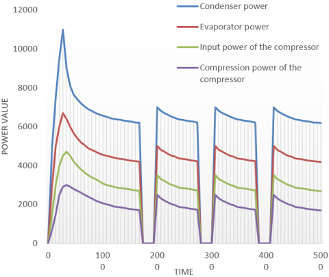
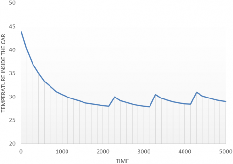
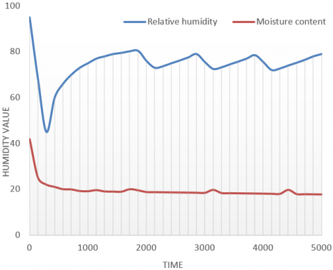
Suppose: during the electric car road test, the ambient temperature is 28℃, the relative humidity is 68%, the rated rotate speed of the air conditioner compressor is 1000r/min, the car speed is 70km/h, there’re four passengers in the car, their average heat load is 150W and average humidity load is 90g/h, the control objective of the temperature inside the car is 26°C. Figure 7 shows the power change of different components under the thermal management state, Figure 8 shows the change of temperature inside the car under the thermal management state, and Figure 9 shows the change of humidity inside the car under the thermal management state.
Figure 6. Dryness and temperature of the coolant in the evaporator
Figure 7. Power change of different components under the thermal management state
According to Figure 7, in the initial working stage of the VTM system, due to the high temperature in the car, the power requirements of the evaporator and compressor of the air conditioning system were relatively high. Then, after operating for 8 minutes, the temperature inside the car decreased, the power requirements of the evaporator and compressor of the air conditioning system stabilized, and the heat exchange rate of the heat exchanger decreased gradually. When the temperature inside the car was lower than the preset temperature control objective value, the evaporator and compressor of the air conditioning system stopped working, and the temperature inside the car increased gradually. When temperature inside the car increased to the preset temperature control objective value, the evaporator and compressor of the air conditioning system started working again, and the temperature inside the car decreased gradually. The continuous cycle of this process can ensure a stable temperature in the car. According to Figure 8, the air-conditioning system can control the temperature in the car at about 26°C after operating for 15 minutes, and the additional dehumidification function of the air-conditioning system can maintain the relative humidity in the car at about 79%.
Figure 8. Change of temperature inside the car under the thermal management state
Figure 9. Change of humidity inside the car under the thermal management state
This paper researched the simulation and multi-objective optimization of the VTM system of electric cars, elaborated on the evaluation methods for the heat dissipation efficiency of the engine cooling system and the cooling efficiency of the air-conditioning system of the electric cars, and gave evaluation ideals of the thermal management performance of the VTM system of electric cars. Then, the paper constructed temperature control optimization objective functions for electric cars under different thermal adaption working conditions such as low speed climbing, medium speed climbing, high speed driving, and idling; after that, through tests, the simulation calculation results of the control objectives of the VTM system of electric cars were compared with the road test results, and it’s verified that the evaluation results of the degree of confidence were relatively ideal. The reliability of the simulation calculation results of the inlet temperature of heat exchanger was verified, and the change curves of the dryness and temperature of coolant in the condenser and in the evaporator were plotted, which further verified that the state distribution of the coolant in the condenser and in the evaporator can basically meet the accuracy requirements of the simulation calculation of the VTM system of electric cars. At last, combining with the road test results of the electric cars, the effectiveness of the proposed strategies for the coordinated control of the VTM system of electric cars had been proved.
[1] Afzal, A., Samee, A.M., Razak, R.A., Ramis, M.K. (2021). Thermal management of modern electric vehicle battery systems (MEVBS). Journal of Thermal Analysis and Calorimetry, 144(4): 1271-1285. https://doi.org/10.1007/s10973-020-09606-x
[2] Lander, L., Kallitsis, E., Hales, A., Edge, J.S., Korre, A., Offer, G. (2021). Cost and carbon footprint reduction of electric vehicle lithium-ion batteries through efficient thermal management. Applied Energy, 289: 116737. https://doi.org/10.1016/j.apenergy.2021.116737
[3] Park, J., Kim, Y. (2019). Supervised-learning-based optimal thermal management in an electric vehicle. IEEE Access, 8: 1290-1302. https://doi.org/10.1109/ACCESS.2019.2961791
[4] Gocmen, S., Gungor, S., Cetkin, E. (2020). Thermal management of electric vehicle battery cells with homogeneous coolant and temperature distribution. Journal of Applied Physics, 127(23): 234902. https://doi.org/10.1063/5.0004453
[5] Amin, M., Ariantara, B., Putra, N., Sandi, A.F., Abdullah, N.A. (2018). Thermal management of electric vehicle batteries using heat pipe and phase change materials. In E3S Web of Conferences, 67: 03034. https://doi.org/10.1051/e3sconf/20186703034
[6] Behi, H., Karimi, D., Behi, M., Ghanbarpour, M., Jaguemont, J., Sokkeh, M.A. (2020). A new concept of thermal management system in Li-ion battery using air cooling and heat pipe for electric vehicles. Applied Thermal Engineering, 174: 115280. https://doi.org/10.1016/j.applthermaleng.2020.115280
[7] Grandjean, T., Barai, A., Hosseinzadeh, E., Guo, Y., McGordon, A., Marco, J. (2017). Large format lithium ion pouch cell full thermal characterisation for improved electric vehicle thermal management. Journal of Power Sources, 359: 215-225. https://doi.org/10.1016/j.jpowsour.2017.05.016
[8] Liu, M., Li, Y., Ding, H., Sarlioglu, B. (2017). Thermal management and cooling of windings in electrical machines for electric vehicle and traction application. In 2017 IEEE Transportation Electrification Conference and Expo (ITEC), pp. 668-673. https://doi.org/10.1109/ITEC.2017.7993349
[9] Aranzabal, I., de Alegria, I. M., Garate, J.I., Andreu, J., Delmonte, N. (2017). Two-phase liquid cooling for electric vehicle IGBT power module thermal management. In 2017 11th IEEE International Conference on Compatibility, Power Electronics and Power Engineering (CPE-POWERENG), pp. 495-500. https://doi.org/10.1109/CPE.2017.7915221
[10] Yuksel, T., Litster, S., Viswanathan, V., Michalek, J.J. (2017). Plug-in hybrid electric vehicle LiFePO4 battery life implications of thermal management, driving conditions, and regional climate. Journal of Power Sources, 338: 49-64. https://doi.org/10.1016/j.jpowsour.2016.10.104
[11] Devahdhanush, V.S., Lee, S., Mudawar, I. (2021). Consolidated theoretical/empirical predictive method for subcooled flow boiling in annuli with reference to thermal management of ultra-fast electric vehicle charging cables. International Journal of Heat and Mass Transfer, 175: 121224. https://doi.org/10.1016/j.ijheatmasstransfer.2021.121224
[12] Pattnayak, R.A., Vijay, T. (2020). Thermal analysis of cell balancing for battery management system in electric vehicle. In 2020 26th International Workshop on Thermal Investigations of ICs and Systems (THERMINIC), pp. 1-7. https://doi.org/10.1109/THERMINIC49743.2020.9420510
[13] Boyer, B., Fiani, P., Sandou, G., Godoy, E., Vlad, C. (2020). Functional model-based resource management: An application to the electric vehicle thermal control. In ICINCO, pp. 565-575.
[14] Choudhari, V.G., Dhoble, A.S., Sathe, T.M. (2020). A review on effect of heat generation and various thermal management systems for lithium ion battery used for electric vehicle. Journal of Energy Storage, 32: 101729. https://doi.org/10.1016/j.est.2020.101729
[15] Biswas, S. (2020). Thermal management system and performance characteristics of electric vehicle. SAE Technical Paper 2020-28-0022. https://doi.org/10.4271/2020-28-0022
[16] Shen, M., Gao, Q., Wang, Y., Zhang, T.S. (2019). Design and analysis of battery thermal management system for electric vehicle. Journal of Zhejiang University (Engineering Science), 53(7): 1398-1406. https://doi.org/10.3785/j.issn.1008-973X.2019.07.020
[17] Docimo, D.J., Pangborn, H.C., Alleyne, A.G. (2018). Hierarchical control for electro-thermal power management of an electric vehicle powertrain. In Dynamic Systems and Control Conference, 51906: V002T19A010. https://doi.org/10.1115/DSCC2018-9215
[18] Smith, J., Singh, R., Hinterberger, M., Mochizuki, M. (2018). Battery thermal management system for electric vehicle using heat pipes. International Journal of Thermal Sciences, 134: 517-529. https://doi.org/10.1016/j.ijthermalsci.2018.08.022
[19] Garrow, S.G., Aksland, C.T., Sharma, S., Alleyne, A.G. (2018). Integrated modeling for battery electric vehicle transcritical thermal management system. In 2018 Annual American Control Conference (ACC), pp. 5632-5638. https://doi.org/10.23919/ACC.2018.8430912
[20] Schaut, S., Sawodny, O. (2019). Thermal management for the cabin of a battery electric vehicle considering passengers’ comfort. IEEE Transactions on Control Systems Technology, 28(4): 1476-1492. https://doi.org/10.1109/TCST.2019.2914888
[21] Wiriyasart, S., Hommalee, C., Sirikasemsuk, S., Prurapark, R., Naphon, P. (2020). Thermal management system with nanofluids for electric vehicle battery cooling modules. Case Studies in Thermal Engineering, 18: 100583. https://doi.org/10.1016/j.csite.2020.100583
[22] Fu, Z., Li, L., Liang, X., Zhu, Q., Cheng, Z. (2019). Thermal management optimization for a wireless charging system of electric vehicle with phase change materials. In E3S Web of Conferences, 118: 02066. https://doi.org/10.1051/e3sconf/201911802066
[23] Arora, S., Tammi, K. (2018). A hybrid thermal management system with negative parasitic losses for electric vehicle battery packs. In ASME International Mechanical Engineering Congress and Exposition, 52071: V06AT08A025. https://doi.org/10.1115/IMECE2018-86111
[24] Liu, Y., Zhang, J. (2021). Electric vehicle battery thermal and cabin climate management based on model predictive control. Journal of Mechanical Design, 143(3): 031705. https://doi.org/10.1115/1.4048816
[25] Li, D., Zhang, C., Fan, R., Xu, L., Wang, Y., Guo, W. (2021). An innovative thermal management method for cooling loop of electric driving system for durable and high efficiency electric vehicle. Applied Thermal Engineering, 117176. https://doi.org/10.1016/j.applthermaleng.2021.117176
[26] Pan, Q.W., Shan, H., Liu, H.R., Wang, R.Z. (2021). A vapor compression-adsorption thermal management system for electric vehicle: Concept and working fluid pairs. Energy Conversion and Management, 238: 114168. https://doi.org/10.1016/j.enconman.2021.114168
[27] Hemmati, S., Doshi, N., Hanover, D., Morgan, C., Shahbakhti, M. (2021). Integrated cabin heating and powertrain thermal energy management for a connected hybrid electric vehicle. Applied Energy, 283: 116353. https://doi.org/10.1016/j.apenergy.2020.116353