Alper Ata* | I. Bedii Ozdemir
© 2021 IIETA. This article is published by IIETA and is licensed under the CC BY 4.0 license (http://creativecommons.org/licenses/by/4.0/).
OPEN ACCESS
The thermal characteristics of turbulent non-premixed methane flames were investigated by four burner heads with the same exit diameter but different heights. The fuel flow rate was kept constant with an exit velocity of 15 m/s, while the co-flow air speed was increased from 0 to 7.6 m/s. The radial profiles of the temperature and flame visualizations were obtained to investigate the stability limits. The results evidenced that the air co-flow and the cone angle have essential roles in the stabilization of the flame: An increase in the cone angle and/or the co-flow speed deteriorated the stability of the flame, which eventually tended to blow off. As the cone angle was reduced, the flame was attached to the bluff body. However, when the cone angle is very small, it has no effect on stability. The mixing and entrainment processes were described by the statistical moments of the temperature fluctuations. It appears that the rise in temperature coincides with the intensified mixing, and it becomes constant in the entrainment region.
turbulent non-premixed flame, methane flame, conical bluff body, flame stability
The combustion mode of operation in newly built residential heating systems has broadly changed from non-premixed to premixed by the enforcement of recent directives [1], which oblige lower combustion emissions and higher thermal efficiencies. Nevertheless, appliances with non-premixed flames are still in use in industrial systems due to the need for higher temperature regimes in the applications, such as steam boilers and furnaces for various production processes. Flame stabilization with bluff bodies is an efficient design method used in the non-premixed forced draught burners [2-7], where the flow downstream of the complex flame holders can be perceived as an axial gaseous fuel jet through a central bluff body and a peripheral co-flowing stream of air [8-16]. This is why single bluff body flames have been systematically investigated in various aspects of fundamental issues. The shape of the bluff body and its effects emerge as an essential attribute in this context, and some specific geometries have been a subject of increased attention in the past: Because of their simple geometry, cylindrical forms have been widely investigated [17-27]. The same is true for the disk- [14, 28-31] and tulip-shaped burners [32-34], but conical bluff bodies [4, 35-37] have been studied only for a limited number of geometrical variations and flow conditions. On the other hand, conical bluff bodies have two significant and easy-to-control parameters, such as the cone angle and the cone diameter, affecting the stability, thermal characteristics, and the emissions of turbulent flames. Therefore, properties of the cone burners need to be explored in new designs.
The research on turbulent non-premixed bluff body stabilized flames has mainly focused on the recirculation region in the wake of flame holders, where fuel and co-flow streams and the mixing layer in between were examined; vortical structures (inner and outer vortices) in the region were described in detail [11, 38, 39, 21]. Based on their work on a cylindrical bluff body, Masri and his co-workers [22, 40] report that three parameters are crucially important for the control of the flame structure: These are the fuel jet momentum, the bluff body size (relative to fuel exit diameter) and the recirculation strength (in relation to co-flow air velocity). The fuel jet momentum has shown to affect the mixture strength in the inner vortex in that, depending on the jet velocity, the reaction zone shifts towards inside or outside [39]. As a result, the reaction zone in the recirculation region becomes thinner at low jet velocities and thicker at higher velocities [21]. However, the effect of the shifting is not so apparent at the locations further downstream of the recirculation region [39]. Ma and Harn [25], working on a conical bluff body with a large cone angle, showed that the large diameters caused an increase in the spread of the wake flow and, therefore, a shorter recirculation length results. In a similar study [26, 27], it was pointed out that as the flame holder becomes wider, the residence time increases, leading to a sooty flame, and this was also shown experimentally by Ata and Ozdemir [2] in their work on the conical bluff bodies.
Depending on the geometry of cylindrical flame holders [27], the co-flow velocity has been shown to affect the structure of the attached flame, such as the recirculation zone length, which has a significant influence on the heat release [41]. The flame length is also known to be another parameter influenced by the co-flow velocity. Contrary to the widespread belief, in that increasing the co-flow decreases the flame length [36, 37, 42, 43], it was experimentally shown [2, 44, 45] that, under certain circumstances (such as the co-flows velocities up to 3 m/s or the bluff body diameters smaller than 18mm) flames can elongate by the increasing the co-flow. In addition to these three parameters, the velocity and the momentum flux ratios of the fuel and air streams were found to have indirect effects on the recirculation strength [11, 21] through the vortex formation mechanisms. Furthermore, the stoichiometric mixture fraction and the heat release rate are the other parameters that shape the flame structure [21].
Apart from the immediate proximity of the burners, portions of bluff body flames far downstream have been of less interest in the literature, although it has been revealed that the downstream end of the flames experiences strong local extinctions, especially when the conditions are close to blow-off [21]. Dally et al. [39] and Yen et al. [37] are rare examples with temperature measurements made up to 15 bluff body diameters. This paper is the outcome of an ongoing investigation on the conical bluff bodies [2, 44] and aims to map the thermal characteristics of the conical bluff body flames up to the full length, which was approximately 55D. Hence, the data set of this study serves as a piece of complementary information to our earlier research on such flames. Next, the experimental configuration and boundary conditions will be introduced. These will be followed by the presentation of the change in the flame stabilization heights together with the visual perception of the flow. Finally, temperature field data will be presented and discussed.
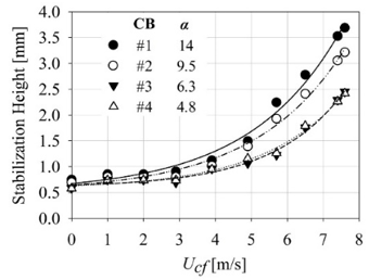
Figure 1 presents the experimental rig schematically, whose details were described in our recent publications [2, 44]. The flame was formed downstream of a non-premixed burner with a conical stabilizer. Four stabilizer bluff bodies were machined conically out of brass and were assembled at the outlet of the fuel pipe with a 12 mm diameter. The heights of conical bluff bodies were varied as 12, 18, 27, and 36 mm, forming half cone angles of 14, 9.5, 6.3, and 4.8 degrees, respectively. In the following, these conical bluff bodies will be coded as CB#1, CB#2, CB#3, and CB#4, respectively.
Standard test grade methane G20 was used as fuel, as in EN 437, with 99.5% CH4 purity. The fuel flow was supplied at a constant volumetric flow rate of 0.68 m3/h in order to provide a fuel velocity (Uf) of 15 m/s at the burner exit (Reynolds number = 3553) that maintains stable turbulent flow conditions at the desired power rate (6.43 kW). The fuel tank was sustained at a stable pressure so that the variation of the volumetric fuel flow was kept at an interval of ±1.5%. The ambient air was delivered by a speed-controlled blower system, where the flow was conditioned with strainers and a honeycomb to minimize the fluctuations prior to the outlet of the burner. The flow rate of the air at the burner exit was changed from 0 to 7.6 m/s. The combustion products were collected by a hood and exhausted with a mechanical ventilation system to prevent contamination in the experimental environment.
The setup included the temperature measurement system, the photography equipment, and a motorized traverse mechanism, all placed in a black-walled cubicle. Digital images of the flames were taken by using a Nikon D80 digital SLR camera equipped with a Nikkor AF-S 18-200 lens. The camera was set to an ISO of 1000, a shutter speed of 1/25 s, and an aperture of F5.6, in order to capture a clear image without graining. Remote triggering allowed a vibration-free tripod.
Figure 1. Set-up and burner head details
The temperature field was measured only for the flame of CB#2 at a co-flow velocity of Ucf = 2 m/s. An unsheathed type-B thermocouple, a 273 K reference probe, and a data acquisition card (DAQAmi 2408) were employed for this purpose. The temperature data were sampled at a rate of 50 Hz for a period of 10 s with an accuracy of ±1.8 K at 523 K and ±3.9 K at 2073 K. The radiation losses were corrected, resulting in an increase of the measured temperatures by 0.6 K for temperatures up to 300 K and an increase of 105 to 122 K for temperatures up to1600 K. The temperature probe scanned the flame radially and vertically on a 2D traverse mechanism. The probe position was aligned with a laser sheet and a caliper/built-in ruler. The vertical movement of the traverse mechanism was manual, and the horizontal movement was power-driven by a step motor and control electronics, which was coded to locate the probe at steps of 1 mm.
3.1 Stabilization height and visual observations of the flame
It is known that the flame anchors to the burner head at a location called stabilization height, where local flow velocity matches the local flame speed [46]. However, this balance is disturbed when the stretching increases with the fuel velocity [47], or the flame is cooled and becomes lean by the excess entrainment of air, or the ignition is prohibited by the hot products entraining and mixing with the fuel jet. As a result, the flame lifts off the burner head, and eventually, a blowout occurs [48, 49].
Figure 2 shows that the stabilization height rises with Ucf and, hence, the flame moves away from the bluff body surface. It is evidenced that the cone angle also affects the stability of the flame, and so the stabilization height: The flame moves downstream as the cone angle is increased from 4.8 degrees in the CB#4 to 14 degrees in the CB#1. It appears that the change of the stabilization height with the cone angle does not have a linear relation. When the cone angle changes from 4.8 degrees (CB#4) to 6.3 degrees (CB#3), the change in stabilization height is either minor or nonexistent. On the other hand, when the cone angle is changed from 9.5 degrees (CB#2) to 14 degrees (CB#1), a much larger change in the stabilization height occurs. The reason for that is because the burner CB#1 has the largest cone angle, and it diverts the co-flow radially outwards stronger than the others, all of which enhances the interactions between the fuel jet and the co-flow. As a result, more air entrains into the fuel flow, deteriorating the local stability of the flame, which results in a shift of equilibrium height slightly farther downstream as described before. However, all flames remain in the jet-dominated regime and are still stable according to the norms set by Tang et al. [35]. In the range of co-flow velocity, 3.9 £ Ucf£ 7.6 m/s, the increased stretching by the higher co-flow velocities suppresses the sooting in the yellow-colored region and turns it into a blue-colored flame zone. In addition, a thickening/brightening of the flame around z = 8D – 9.5D is attributed to the stronger recirculation region (by increased Ucf), which is enhancing the mixing in that specific part of the flame, as pointed out by Masri and his co-workers [21, 39].
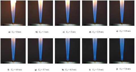
As it can be seen clearly in Figure 3a similar features were observed in all flames and, thus, in order to avoid repetitions, full length temperature measurements were made only for the burner with CB#2. Flames were presented in the upstream region of the flow (Figure 3b) with an emphasis on the effect of varying co-flow velocities. In the absence of the co-flow (Ucf = 0, Figure 3b.a), the flame initiates just over the upper face of the bluff body and attaches to the burner head only in a small region in the vicinity of the fuel exit (at around r = 0.55 rbb). The effect of the cone on the flame is rather limited, and no recirculation region is formed in the wake of the bluff body. As a result, a blue-colored flame develops without a waist downstream of the burner. This is a clear indication of weak interaction between the fuel and the ambient air. As the fuel/air mixing improves farther downstream, the flame is colored yellow. However, since there is no recirculation region, the residence time is too short to form soot particles near the burner head [24]. When the co-flow is introduced (Fig. 3b.b, Ucf = 1 m/s), the flame structure starts to change with the appearance of stronger interactions between the fuel jet and the co-flow air in the wake region. The flame attachment now moves towards the outer edge of the burner head (r = 0.64 rbb). Since, at this Ucf, the stretching in the near field is still high enough, and the recirculation has not been well established yet, an initiation of a waist formation can only occur at most. However, an additional increase in the co-flow velocity (Ucf = 2 m/s, Figure 3b.c) leads to a clear waist formation in the bluff body wake, which is also an indication of the presence of a recirculation region. The flame attachment area enlarges to r = 0.75 rbb. When the co-flow velocity reaches 2.9 m/s (Figure 3b.d), the flame fully attaches to the upper surface of the cone, r = rbb, exhibiting a well-defined waist. Further increasing the co-flow velocity, 3.9 £ Ucf£ 7.6 m/s (Figure 3b.e–j), gradually changes the flame, in that the stabilization height of the flame increases (see also Figure 2), the yellow-colored region shrinks, and the flame thickens and brightens just above the waist region approximately at a vertical location of z = 8D – 9.5D.
Figure 2. Flame stabilization
3.2 Temperature field
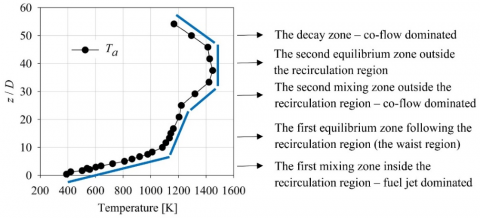
The mean temperature variation along the centerline, Ta, is presented in Figure 4 for the burner CB#2 with Ucf = 2 m/s, which reveals that the flame is strongly affected by the mixing process. In the first mixing zone in the recirculation region, the flame is driven by the dynamics of the fuel jet, where the temperature increases from the exit value (400 K) to 1100 K level. Outside the recirculation region, where the fuel jet and the co-flow air confronts, the enthalpy of combustion is consumed by the process of heating of the co-flow and, therefore, the temperature remains constant. This region corresponds to the waist zone. Farther downstream, the mixing process intensifies once again in the region dominated by the co-flow, where the temperature increases further to a level of 1430 K. Following this zone, increases in air entrainment and combustion products dilute the mixture towards the lean side of the stoichiometry, leading first to a leveling in temperature variation and then a decaying trend follows.
(a) Visual observations of the CB#1 - #2 - #3 - #4 flames
(b) Visual observations of the CB#2 flame (D = 12, H = 18mm).
Figure 3. Visual observations of flames
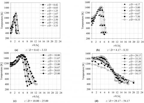
The time averaged temperature profiles of the burner CB#2 are presented in Figure 5 at elevations between z / D = 0.42 – 54.17. Radial data were collected on a linear path from the centerline towards the outskirts of the flame with a resolution of 1 mm. The tests were performed while co-flowing air velocity was fixed at 2 m/s (see Figure 3b.c).
Close to the burner, z / D = 0.42 – 3.33 (Figure 5a), the temperature profiles seem to overlap on the shear layer on the fuel side, whereas they spread on the air side, and this increases with the distance from the burner. At locations between z/ D = 0.42 – 1.25, the temperature reaches a peak (Tmax) of 960 K at r/0.5df = 1.5. The peak value gradually increases up to 1205 K at z / D = 3.33 and moves radially outwards to r/0.5df = 2.5. Considering the temperature profiles between z / D = 4.17 – 8.33 (Figure 5b), we observe that the steepness of the gradient on the fuel side of the peak temperature become milder as the distance to the burner increases. However, the gradient on the co-flow side remains very sharp while shifted radially outwards with the peak temperature. This means that the mixing near the co-flow is not as effective as the fuel side so that the composition remains very lean, as also reported by Becker and Yamazaki [50] and Mahmud et al. [51]. The temperature profiles at locations between z / D = 10 – 25 (Figure 5c) show that the temperature remains constant in the core region of the fuel jet and increases sharply in the shear layer till the peak value is reached. On the co-flow side, the temperature drops sharply but with gradients changing with the distance to the burner. The profiles are distinctly different in the region z / D ≥ 29.17 (Figure 5d), which covers the upper half of the flame where the fuel and air streams are well mixed. The temperature reaches a peak at the center and decreases radially outwards. The maximum temperature in these profiles decreases with the distance from the burner, partly due to the spread of the flame to a wider zone [37], which is difficult to sustain at high temperatures.
Figure 4. Temperature variation along the centerline
Figure 5. Radial profiles of temperature
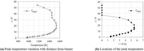
We know from the chemical kinetics that the peak temperatures (Tmax) mostly follow the flame front, where the value of the mixture fraction occurs very close to the stoichiometric value. Figure 6a presents the variation of the peak temperatures with a distance from the burner. The peak temperature increases in the recirculation region from 960 K (at z / D = 0.42) to 1535 K (at z / D = 20.8) and, then, drops to 1447 K at the beginning of the second equilibrium zone (at z / D = 29.2). Beyond this zone, the peak temperature occurs at the centerline, as seen in Figure 6b and, thus, both Ta and Tmax coincide and decrease in the decay zone.
Figure 7 presents the first (mean), second (variance), third (skewness), and fourth-order moments (flatness/kurtosis) of the temperature data. The moments at each measurement point were calculated by using the data that consists of 500 measurements per point, as described in section 2. Figure 7a is a contour map of the temperature data, where the mean temperatures vary between 335 K – 1535 K. The low temperatures are found on the outskirts of the flame in a layer which is very thin in upstream regions, indicating a steep temperature gradient, and becomes thicker at the downstream locations, indicating a milder temperature gradient. The lowest temperature in the flame happens in the fuel jet close to the outlet, which penetrates almost up to the half of the flame length (z / D ≈ 29). The high temperatures at the lower half of the flame (z / D = 10 – 30) occur in a region where a stoichiometric mixture is achieved. Farther downstream, z / D > 30, the hot spots then move into the center, as observed in Fig. 6b. Figure 7b provides the contours of the second moment (variance) of the temperature, which indicates the magnitude of fluctuation around the mean temperature. It is evident that the variance gradually increases with distance from the burner and reaches its maximum just after the waist region, z / D > 25, with a radial span in between r / 0.5df = 8 – 11. It is known that this is the region where the flame is disturbed by co-flowing air. Figure 7c shows the contours of the skewness (as a measure of asymmetry), which varies between -1.4 and 1.54 in the current case. The probability density function (pdf) of temperature seems to be negatively skewed (with a tail extending to minus infinity), s < ̶ 0.2, between the fuel jet and the air co-flow. This indicates that the large fluctuation velocities in the negative direction (radially inwards) are not occurring frequently in this region; that is to say, the entrainment of the co-flow is very weak. On the outer region of the flame upstream, where s > 0.2, temperature pdf has a tail extending to plus infinity, which means that small and possibly negative fluctuation values predominantly occur. This implies that in the zone immediately next to the wake region strong air entrainment into the flame occurs. Fig. 7d presents the flatness (kurtosis) of the temperature pdf. We know that the flatness, f, describes if the fluctuations cumulate around the mean (low kurtosis) or have intermittent peaks (high kurtosis), and, when f is equal to 3, it means that the pdf has a Gaussian distribution. It seems that the isolated zones of higher flatness (f > 3) are generally located in the high temperature region due to inward convection. The flatness is also high in the outskirts of the flame because of the air entrainment.
Figure 6. Peak temperatures
Figure 7. a. Distribution of mean temperature - first moment; b. Distribution of variance – second moment; c. Distribution of skewness – third moment; d. Distribution of flatness – fourth moment
A series of experiments were conducted in order to build a better understanding of the behavior of turbulent, nonpremixed flames stabilized by conical bluff bodies. The experiments were performed using bluff bodies of the same diameter in 4 different lengths. The fuel exit velocity was kept constant at 15 m/s in all cases, and the peripheral air co-flow was varied between 0 – 7.6 m/s. The visual observations of the near field of the flame were presented together with the radial profiles of the temperature.
The experiments revealed that the attachment of the flame was noticeably modified by the peripheral air co-flow, which formed a recirculation zone behind the bluff body. Increasing the co-flow enhanced the toroidal vortices inside the circulation zone and hence the mixing immediately next to the burner. This led to the formation of a waist next to the recirculation zone. Further increase in the co-flow velocity thickened the neck region and decreased the soot formation. Visual observations revealed that the yellow-colored regions transformed into blue when the co-flow Ucf ≥ 3.9 m/s.
The results also showed that the cone angle influences the stability of the flame. As the cone angle was increased, the flame anchored away from the burner. This deteriorated the stability of the flame, which became more prone to the blow-off. On the other hand, when the cone angle became narrower, the flame had a tendency to stabilize close to the bluff body. However, the results showed that the stabilization heights for half cone angles of 6.3 and 4.8 degrees were almost identical, indicating that there is a limit for that: the cone angle has no effect on the stability if it is very narrow (less than 6.3 degrees).
The statistical analyses of the temperature fluctuations revealed that the flame was strongly affected by the mixing and entrainment processes. The regions where these processes were active were distinctly marked by the skewness of the fluctuations. The radial temperature gradients evidenced that the mixing was more effective on the fuel jet side in the lower half of the flame. The variation of the mean temperature along the centerline showed that the temperature rose only in the intensified mixing zones yet leveled in the equilibrium region and finally decreased in the decay zone.
|
d |
fuel pipe external diameter, mm |
|
dair |
diameter of the air pipe, mm |
|
df |
fuel pipe internal diameter, mm |
|
D |
bluff body diameter, mm |
|
f |
value of flatness |
|
H |
bluff body height, mm |
|
r |
location on the radial axis, mm |
|
rbb |
bluff body radius, mm |
|
s |
value of skewness |
|
T |
temperature, K |
|
Ta |
local temperature on the central axis, K |
|
Tmax |
local maximum temperature at a specific z height, K |
|
Uf |
fuel velocity at the fuel exit plane, m.s-1 |
|
Ucf |
coflow air velocity, m.s-1 |
|
z |
location on the longitudinal axis, mm |
|
Greek symbols |
|
|
a |
half cone angle, degrees |
|
Subscripts |
|
|
a |
axis |
|
air |
air |
|
bb |
bluff body |
|
cf |
coflow |
|
f |
fuel |
|
max |
maximum |
|
Abbreviations |
|
|
CB |
conical bluff body |
[1] European Commission. (2013). Ecodesign requirements for space heaters and combination heaters. Commission Regulation (EU) No 813/2013.
[2] Ata, A., Ozdemir, I.B. (2019). Effects of the cone angle on the stability of turbulent nonpremixed flames downstream of a conical bluff body. Heat Mass Transfer, 56(5): 1627-1639. https://doi.org/10.1007/s00231-019-02789-6
[3] Turns, S.R. (2000). An Introduction to Combustion: Concepts and Applications Second Edition, McGraw-Hill, Singapore, 18-24.
[4] Peters, N. (2002). Turbulent Combustion. Cambridge University Press, Cambridge, 170-172.
[5] Günther, R., Wittmer, V. (1981). The turbulent reaction field in a concentric diffusion flame. Eighteenth Symposium (International) on Combustion, 18(1): 961-967. https://doi.org/10.1016/s0082-0784(81)80100-2
[6] Basu, P., Kefa, C., Jestin, L. (2000). Boilers and Burners Design and Theory, Springer-Verlag, New York, 108-118.
[7] Baukal, C.E.J. (2000). Heat Transfer in Industrial Combustion. CRC Press LLC, Florida, 8-21.
[8] Dally, B.B., Masri, A.R. (1996). Turbulent nonpremixed flames stabilised on a bluff-body burner. Proceedings of the International Workshop on Measurement and Computation of Turbulent Nonpremixed Flames, 1: 47-52.
[9] Masri, A.R. (1998). Computation of bluff-body stabilised jets and flames. Proceedings of the Third International Workshop on Measurement and Computation of Turbulent Nonpremixed Flames, Section 4: 1-21.
[10] Kalt, P.A.M., Masri, A.R. (2002). Bluff-body stabilised jets and flames. Sixth International Workshop on Measurement and Computation of Turbulent Nonpremixed Flames, 137-171.
[11] Dally, B.B., Fletcher, D.F., Masri, A.R. (1998). Flow and mixing fields of turbulent bluff-body jets and flames. Combust Theor Model, 2(2): 193-219. https://doi.org/10.1088/1364-7830/2/2/006
[12] Kundu, K.M., Banerjee, D., Bhaduri, D. (1980). On flame stabilization by bluff-bodies. J Eng Power-T Asme, 102(1): 209-214. https://doi.org/10.1115/1.3230225
[13] Guo, P., Zang, S., Ge, B. (2010, May). Technical brief: Predictions of flow field for circular-disk bluff-body stabilized flame ınvestigated by large eddy simulation and experiments. J Eng Gas Turb Power, 132(5): 054503. https://doi.org/10.1115/1.3205029
[14] Chen, Y.C., Chang, C.C., Pan, K.L., Yang, J.T. (1998). Flame lift-off and stabilization mechanisms of nonpremixed jet flames on a bluff-body burner. Combust Flame, 115(1-2): 51-65. https://doi.org/10.1016/s0010-2180(97)00336-2
[15] Mishra, D.P., Kiran, D.Y. (2009). Experimental studies of bluff-body stabilized LPG diffusion flames. Fuel, 88(3): 573-578. https://doi.org/10.1016/j.fuel.2008.09.027
[16] Correa, S.M., Gulati, A. (1992). Measurements and modeling of a bluff body stabilized flame. Combust Flame, 89(2): 195-213. https://doi.org/10.1016/0010-2180(92)90028-n
[17] Namazian, M., Kelly, J., Schefer, R.W. (1992). Concentration imaging measurements in turbulent concentric-jet flows. AIAA J, 30(2): 384-394. https://doi.org/10.2514/6.1989-58
[18] Schefer, R.W., Namazian, M., Kelly, J. (1994). Velocity measurements in turbulent bluff-body stabilized flows. AIAA J, 32(9): 1844-1851. https://doi.org/10.2514/3.12182
[19] Schefer, R.W., Namazian, M., Kelly, J. (1987). Velocity measurements in a turbulent nonpremixed bluff-body stabilized flame. Combust Sci Technol, 56(4-6): 101-138. https://doi.org/10.1080/00102208708947084
[20] Roquemore, W.M., Tankin, R.S., Chiu, H.H., Lottes, S.A. (1986). A study of a bluff-body combustor using laser sheet lighting. Combust Sci Technol, 4(4): 205-213. https://doi.org/10.1007/bf00717816
[21] Masri, A.R., Kelman, J.B., Dally, B.B. (1998). The instantaneous spatial structure of the recirculation zone in bluff-body stabilized flames. Twenty-Seventh Symposium (International) on Combustion, 27(1): 1031-1038. https://doi.org/10.1016/s0082-0784(98)80503-1
[22] Masri, A.R., Dibble, R.W., Barlow, R.S. (1996). The structure of turbulent nonpremixed flames revealed by Raman-Rayleigh-LIF measurements. Prog Energy Combust, 22(4): 307-362. https://doi.org/10.1016/s0360-1285(96)00009-3
[23] Masri, A.R., Dally, B.B., Barlow, R.S., Carter, C.D. (1994). The structure of the recirculation zone of a bluff-body combustor. Twenty-Fifth Symposium (International) on Combustion/The Combustion Institute, 25(1): 1301-1308. https://doi.org/10.1016/s0082-0784(06)80771-x
[24] Ozdemir, I.B. (2018). A modification to temperature-composition pdf method and its application to the simulation of a transitional bluff-body flame. Comput Math Appl, 75(7): 2574-2592. https://doi.org/10.1016/j.camwa.2017.12.031
[25] Ma, H.K., Harn, J.S. (1994). The jet mixing effect on reaction flow in a bluff-body burner. Int J Heat Mass Tran, 37(18): 2957-2967. https://doi.org/10.1016/0017-9310(94)90350-6
[26] Rowhani, A., Chinnici, A., Evans, M.J., Medwell, P.R., Nathan, G.J., Dally, B.B. (2018). Variation of residence time in non-premixed turbulent bluff-body ethylene flames as a function of burner diameter. 21st Australian Fluid Mechanics Conference, Adelaide, Australia.
[27] Rowhani, A., Sun, Z.W., Medwell, P.R., Alwahabi Z.T., Nathan, G.J., Dally, B.B. (2019). Effects of the bluff-body diameter on the flow-field characteristics of non-premixed turbulent highly-sooting flames. Combust Sci Technol. https://doi.org/10.1080/00102202.2019.1680508
[28] Yang, J.T., Chang, C.C., Pan, K.L. (2002). Flow structures and mixing mechanisms behind a disc stabilizer with a central fuel jet. Combust Sci Technol, 174(3): 93-124. https://doi.org/10.1080/713712993
[29] Huang, R.F., Lin, C.L. (1994). Characteristic modes and thermal structure of nonpremixed circular-disc stabilized flames. Combust Sci Technol, 100(1-6): 123-139. https://doi.org/10.1080/00102209408935449
[30] Huang, R.F., Lin, C.L. (2000). Velocity fields of nonpremixed bluff-body stabilized flames. J Energ Resour-ASME, 122(2): 88-93. https://doi.org/10.1115/1.483166
[31] Yang, J.T., Chang, C.C., Pan, K.L., Kang, Y.P., Lee, Y.P. (2002). Thermal analysis and PLIF imaging of reacting flow behind a disc stabilizer with a central fuel jet. Combust Sci Technol, 174(3): 71-92. https://doi.org/10.1080/713712996
[32] Esquiva-Dano, I., Nguyen, H.T., Escudié, D. (2001). Influence of a bluff-body's shape on the stabilization regime of non-premixed flames. Combust Flame, 127(4): 2167-2180. https://doi.org/10.1016/s0010-2180(01)00318-2
[33] Esquiva-Dano, I., Escudié, D. (2005). A way of considering the influence of the bluff-body geometry on the nonpremixed flame stabilization process. Combust Flame, 142(3): 299-302. https://doi.org/10.1016/j.combustflame.2004.10.001
[34] Pinguet, G., Escudié, D. (2007). Experimental study of the stabilization process of a non-premixed flame via the destabilization analysis of the blue ring flame. Exp Therm Fluid Sci, 31(5): 453-460. https://doi.org/10.1016/j.expthermflusci.2006.04.014
[35] Tang, H., Yang, D., Zhang, T., Zhu, M. (2013). Characteristics of flame modes for a conical bluff body burner with a central fuel jet. J Eng Gas Turb Power, 135(9): 091507. https://doi.org/10.1115/1.4024951
[36] San, K.C., Huang, Y.Z., Yen, S.C. (2013). Flame Patterns and Combustion Intensity Behind Rifled Bluff-Body Frustums. J Eng Gas Turb Power, 135(12): 121502. https://doi.org/10.1115/1.4025262
[37] Yen, S.C., Huang, Y.Z., San, K.C. (2015). Thermal characteristics and exhaust-gas analysis behind bluff-body frustums. Fuel, 159: 519-529. http://dx.doi.org/10.1016/j.fuel.2015.07.021
[38] Lee, C.E., Onuma, Y. (1994). Experimental Study of turbulent diffusion flames stabilized on a bluff body: Flame structure. JSME International Journal Series B, 37(1): 165-171. https://doi.org/10.1299/jsmeb.37.165
[39] Dally, B.B., Masri, A.R., Barlow, R.S., Fiechtner, G.J. (1998). Instantaneous and mean compositional structure of bluff-body stabilized nonpremixed flames. Combustion and Flame, 114(1-2): 119-148. https://doi.org/10.1016/s0010-2180(97)00280-0
[40] Masri, A.R., Dibble, R.W., Barlow, R.S. (1992). Raman-Rayleigh measurements in bluff-body stabilised flames of hydrocarbon fuels. Symposium (International) on Combustion, 24(1): 317-324. https://doi.org/10.1016/s0082-0784(06)80042-1
[41] Li, K., Tankin, R.S. (1987). A study of cold and combusting flow around bluff-body combustors. Combustion Science and Technology, 52(4-6): 173-206. https://doi.org/10.1080/00102208708952576
[42] Yen, S.C., Shih, C.L., San, K.C. (2017). Non-premixed flame characteristics and exhaust gas concentrations behind rifled bluff-body cones. J Energy Inst, 91(4): 489-501. https://doi.org/10.1016/j.joei.2017.04.008
[43] Elbaz, A.M., Zayed, M.F., Samy, M., Roberts, W.L., Mansour, M.S. (2015). The flowfield structure of highly stabilized partially premixed flames in a concentric flow conical nozzle burner with coflow. Exp Therm Fluid Sci, 73: 2-9. http://dx.doi.org/10.1016/j.expthermflusci.2015.08.016
[44] Ata, A., Ozdemir, I.B. (2020) Study on the effects of cone height on the turbulent non premixed flames downstream of a conical bluff body. J Therm Sci Eng Appl, 13(3): 031022. https://doi.org/10.1115/1.4048678
[45] Ata, A., Ozdemir, I.B. (2020). New concepts in gas burner design for reduced emissions, IV. International Conference on Fossil & Renewable Energy, Houston, TX.
[46] Gollahalli, S.R., Savaş, Ö., Huang, R.F., Rodriquez Azara, J.L. (1988). Structure of attached and lifted gas jet flames in hysteresis region. Symposium (International) on Combustion, 21(1): 1463-1471. https://doi.org/10.1016/s0082-0784(88)80379-5
[47] Navarro-Martinez, S., Kronenburg, A. (2011). Flame stabilization mechanisms in lifted flames. Flow, Turbulenceand Combustion, 87(2-3): 377-406. https://doi.org/10.1007/s10494-010-9320-1
[48] Broadwell, J.E., Dahm, W.J.A., Mungal, M.G. (1985). Blowout of turbulent diffusion flames. Symposium (International) on Combustion, 20(1): 303-310. https://doi.org/10.1016/s0082-0784(85)80515-4
[49] Ata, A. (2003). Effects of D.C. electric fields and acoustic excitation on the lean limit stability of bluff-body stabilized conical, turbulent premixed flames [master’s thesis], University of Connecticut, CT, USA.
[50] Becker, H.A., Yamazaki, S. (1978). Entrainment, momentum flux and temperature in vertical free turbulent diffusion flames. Combustion and Flame, 33: 123-149. https://doi.org/10.1016/0010-2180(78)90055-x
[51] Mahmud, T., Sangha, S.K., Costa, M., Santos, A. (2007). Experimental and computational study of a lifted, non-premixed turbulent free jet flame. Fuel, 86(5-6): 793-806. https://doi.org/10.1016/j.fuel.2006.08.030