Chirag Sharma | Siddhant Kumar | Aanya Singh | Kartik R. Bhat Hire | Vedant Karnatak | Varun Pandey | Jeet Gupta | Rishabh Shrimali | Sanjay Singh | Shoaib Sultan Noorsha | Edison Gundabattini*
© 2021 IIETA. This article is published by IIETA and is licensed under the CC BY 4.0 license (http://creativecommons.org/licenses/by/4.0/).
OPEN ACCESS
Developments in the gas turbine technology have caused widespread usage of the Turbomachines for power generation. With increase in the power demand and a drop in the availability of fuel, usage of turbines with higher efficiencies has become imperative. This is only possible with an increase in the turbine inlet temperature (TIT) of the gas. However, the higher limit of TIT is governed by the metallurgical boundary conditions set by the material used to manufacture the turbine blades. Hence, turbine blade cooling helps in drastically controlling the blade temperature of the turbine and allows a higher turbine inlet temperature. The blade could be cooled from the leading edge, from the entire surface of the blade or from the trailing edge. The various methods of blade cooling from leading edge and its comparative study were reviewed and summarized along with their advantages and disadvantages.
aerofoils, blade cooling, blade material, jet impingement, leading edge, turbulator, truncated ribs, continuous ribs, trailing edge
Economic sustenance of any nation requires industries and infrastructure. The primary, secondary and tertiary sectors of the economy are perennially evolving and so is the distribution and demography of the consumers of these goods and services. However, it is the undeniable role of the energy sector to bolster this complex and delicate system. Growing population has augmented the stress on economic growth drastically and this has led to an increase in the energy demand. Previously, the entire energy requirement was fulfilled using coal via thermal power plants or crude oil-based gas turbine power plants. But due to the rising concern of climate change renewables have been introduced. This has reduced the share of coal-based plants or gas turbine-based plants to 63% [1].
Although considered congruent to sustainability, renewable energy is seasonal and varies dramatically with geography and climate. This makes it tough to integrate renewable energy systems like solar or wind with the grid, let alone completely replacing it. Moreover, renewable energy and its storage techniques have not fully matured yet. Hence, most of the integration techniques need a backup supply from the grid in case of low production from renewable sources for base load. Therefore, turbine based powerplants have a significant moment in the energy sector till the sustainability and technical feasibility gap exists.
Higher the firing temperature, higher is the efficiency of the gas turbine. However, high temperature application in turbine blades is kept limited as they may result in a possible rupture, bending, or even complete failure of the blades. Thus, the development and the underlying research of an efficient and effectual internal cooling system for gas-turbine blades is vital. Simultaneously, the necessity to ensure minimum impedance and losses in the thermodynamic performances of the turbine is vital as well. Researchers have been working for many years to find and fine tune designs for the cooling channels that provide high transfer, while minimize the pressure drop [2]. This is possible only by enhancing the gas’s turbine inlet temperature (TIT), which ensures that the work done by the turbine in the expansion process is high. The work done by the turbine is what is converted to electrical energy. However, the temperature of the turbine inlet governed by blade material properties of the turbine. The temperature shouldn’t be high enough to weaken the blade material and cause damage to the turbine. Therefore, turbine blade cooling is employed to this temperature blades could be brought down and the turbine inlet temperature could be raised. The blade could be cooled internally from the leading edge and trailing edge or using its entire surface by film cooling. Thin tubes are laid inside the blade where the secondary fluid flows as it cools the blade. Small holes could be made on the leading or trailing edge from where this secondary fluid is injected outside as it forms a layer over the blade and protects it from the hot working fluid. Air is used as a coolant in most of the gas turbines but water and steam could also be used since as they have a higher specific heat. Blade cooling helps to increase the TIT beyond the temperature limit of the material and helps in augmenting the efficiency and power output.
With the growing investment and study on renewable energy-based systems, biofuels and solar thermal power plants are being used to run gas turbines or to produce steam for electricity [3]. Although the fuel used for these plants is different, their working principle requires the use of efficient turbines. Hence, understanding these cooling methods is imperative for better utilization of pre-existing power plants and also, for the transition from conventional to renewable energy sources.
Turbine blades square measure cool [4-6] and air taken from a turbine engine used device. As these emissions reduce the effectiveness of energy and engine power output, the cooling initiative and improvement of certain pure turbine figures have to be understood thoroughly under automotive operating conditions. The connected turbine blades [7, 8] each inside and far, Figure 1 shows the common cooling structure that exists and the three internal cooling zones that are essential to the turbine blade with the most important film [4, 9, 10] within the front edge, weight and shaving areas, and in the edge region. The large edge is cooled using the turbulence [4, 11] and film coating [7, 12], the middle section is covered with infinite sections blocked by ribs with traditional film coating, and the edge is cooled with the help of pine pins using the twisting edge. Internal cooling basically, transfers the coolant through many small pores inside the stains and removes heat from the surface of the stains. There, jet impingement cooling [7, 11], turbulators [5, 10], holes and pin-blade cooling scale are used as internal cooling device. External cooling i.e., film cooling, here ventilation with a separate opening to introduce the agent film to ensure the protection of the surface outside the blades from high temperature gases. The engine cooling frame safe guard the highest gradients and surface temperatures throughout the square work area correspond to the blade pressure limit allowed for the entire planning time.
Figure 1. Blade cooling chart of gas turbine: (i) film cooling (ii) internal cooling [13]
2.1 Types of internal cooling, Figure 2
Figure 2. Factors impacting the rate of heat transfer in internal turbine blade cooling
2.1.1 Impingement cooling
Impingement cooling [4, 9, 10] is usually used near the front of the aerofoils, wherever the heating elements are right. With cooling jets to impinge (impinging) [11, 13] the chin wall, the input cooling is done by the forearm in cooling air [5, 7] due to the heavy blade closed in this space. Even near the 50% chord line same thing could be done. Many factors should be considered in developing economic cooling styles [14]. The effect of the size and size distribution of the jet-hole, cross-section of the cooling channel, and the surface where it is guided all have significant consequences for the continuous heat distribution [5]. Jet impingement [10, 11] near the rotor of the blade is in the form of a jet hitting a flat plate; however, the sharp forward curve of the four should be considered at the same time as the use of the curve at this time.
2.1.2 Pin fin cooling
Due to the limitations within the very small edges of the distance, cooling with pin-fins [4, 10] is often used where it is common to intensify heat transfer from a closed plate in these areas. Anchors usually have a relationship of height to a width ranging from ½ to 4. The heat is transferred to the same pin-Fin arrangements from the other colour and wall to finish the graceful channel and various pins. In pin-fin cooling investigation several factors have to be considered such as pin-fin array type [4, 7] where the space between the pins influences the distribution of heat transfer within the channel. In this cooling method pin size and the form too have a positive effect on heat transfer [4]. The pin fins located at the corners or the periphery of the tip force the vortices generated towards the tip wall thereby enhancing the turbulent mixing of the hot fluid with the incoming cold fluid [15].
2.1.3 Dimple cooling
Dimpled cooling [4, 13] could be a very interesting method because of consequences of relative losses (compared to pins) and heat transfer with a low degree of reduction. Concave tones create a separation of the flow and the regeneration of two vortices [5]. Areas where heat transfer is a testament to the high ground flow of the ground in real time downstream. The heat transfer within the marker channel is usually twice as large as [10, 13] than the heat transfer during the alternating channel for double to four times the loss of the smooth channel [13].
2.1.4 Rib turbulated cooling
Rib turbulators [4, 9, 10] are the main method used to enhance heat transfer within cool small internal corridors. The promoters of rib turbulence are often sewn together on the walls of a cool way, opposite to one another. The permissible heat from the pressure points on the wall of the turbine is transmitted to the agent passing inside. Ribbed channel heat transfer efficiency depends on factors such as channel ratio, rib suspension, therefore, it depends on the Reynolds number of coolant flow [10, 13].
2.2 Types of external cooling, Figure 3
2.2.1 Film cooling
It [4, 9, 13] is a prevalent technology that allow modern gas circulation engines to achieve greater temperatures with shooting, high efficiency, and longevity. In the rotating engine of a cold film [7, 12], it is like the cool air from inner side of the case to the outer surface, eventually safeguarding like a protective layer cool between the newly formed gases and the outer part. These film patterns [4, 12] (e.g., film location, distribution, angle, and position) contribute to the cooling performance of the film [12].
2.2.2 Swirl cooling
In a broader sense, the surface of the concavity flows in one large area called the vortex technology [5, 13], which includes multiple pathways which means the establishment of vertical flow or rotating turbines [5]. Another rising vortex technology [12] is that the use of different wall jets is embedded in the bursiform cooling pads, or in parts of the inner wall to make the most complete movements. This cooling method is commonly referred to as swirl cooling [12, 13], and in addition the cooling of the hurricane provides equilibrium with equal heat transfer in which a direct impact is applied [12].
2.2.3 Lattice cooling
With this cooling system [5, 7, 10], cooling takes place through cross-cutting channels that form sub-structures. The 2 sections of the channels below the channels are thought to be contradictory, or cut in the style. When the cooling flow enters a large network, such as in the root zone of the blades, it basically requires couplings within the upper channels and very little or no coupling between the high and low channels below is needed in lower channels. In this cooling method cooling is from the sides of the tent network wherever underground channels meet at the common "dead ends" or "bind" walls [5, 12], this could be the inner rib [16, 17] or the outer wall design aerofoil [10, 13].
Figure 3. Parameters effecting the cooling performance in external cooling
Fluid streams inside rotating channels [13, 18] are unique in relation to those in stationary channels since rotation incites Coriolis [13] and high-power that generates cross stream auxiliary stream inside the coolant chamber which is rotating subsequently [14, 18]. Heat transfer on the local surface and augmentation levels are mostly changed as of the presence of the rotations in comparison to non-rotating factor. By over viewing the paper one thing is significant that by increasing heat transfer only on single side of chamber intended for cooling down, results in increasing rotations directly and decrease heat transfer on other face of rotary cooling station, which also depends on the inflow and outflow of the fluid radially in the cooling chamber [14]. Neglecting the rotational impact of the fluid [14, 18], the coolant entering from outside will be overcooled while that from the opposite side would be very hot. Ongoing investigations concentrate on the consolidated impacts due to rotation, shape of the channel, and aspect ratio average phase transfer rate of coolant rotor with different turbulators [13]. Results from the paper tells and shows the shape of the channel/tube, direction of channel, rib shape [16] and many more factors like aspect ratio etc. These mentioned factors completely change the distribution of local heat transfer in rotating cooling circuits with turbulators, Figure 4. Also, the conclusions and results from this paper tells that much negative impacts on the rotor has been created with impinging jets and impingement cooling effect has been reduced by the rotation of the rotor, Figure 5 [13, 14].
Figure 4. Parameters influencing heat transfer rate in rotating cooling circuits with turbulator
Figure 5. Secondary flow due to rotation and ribs [13]
For turbine blades, it is necessary to adopt the correct cooling technology at any thermal power plant. Cooling could be used for important blades up to 800℃ depending on temperature and various liquids. Three liquids were evaluated based on cooling capacity, which are as open-air cooling, open circuit steam cooling (OCSC) [6, 19] and closed loop vapor cooling (CLSC) [19]. Turbine performance is estimated in terms of the principal variables with these three methods, including turbine inlet temperature, the compressor pressure ratio and cooling mass ratio. The variables other than turbine performance are known secondary variables and include the geometry, aerothermodynamics and heat transfer parameters of the gas turbine blades. Film cooling [12] refers to the repetitiveness of the secondary fluid in one or more different positions along the surface of the blade which has been endowed with high temperature weathering. The secondary fluid restricts the blade from having direct contact with the hot fluid in various locations such as injected areas and also in the upstream areas, Figure 6.
Most turbines use air as a cooling medium, but steam could absorb more heat than air and therefore provide some performance benefits. Steam cooling results in increased turbine inlet temperature to the temperature where air cooling is not needed. Therefore, this cycle increases efficiency and improves power generation [6].
Figure 6. Influencing parameters in turbine performance
The cooling technology here is the depiction of the internal cooling of the gas turbine blade by air or steam using the cooling path of the same area of cross sectional. In the CLSC [19, 20] steam could cool the turbine blades and further increase the output and efficiency by driving the turbine's lower wheel using heat taken from the turbine's high cycle. In this situation the pressure and heat losses are obvious, and no pumping and mixing is required. Effect of cold vapor on the aerofoil flow field is not significant, therefore, the mixing losses are negligible.
The system, combined with air cooling, gives the required product when operating for design specifications. In OCSC, steam is drawn from the bottom wheel to cool the turbine. The coolant used gets in contact with the flow of air after removing the heat from the blade. The point to note is that the losses due to mixing and diffusion are proportional to the coolant flow [19]. After conducting the necessary analysis on the turbine blades with the specified geometry and data, it was found that the CLSC offers the best value for specific power and overall efficiency, followed by OCSC and air cooling. Various models and governing equations for turbine blade cooling have been developed with respect to cooling gas blade turbine models based on the air / gas property, compressor, combustion chamber and air film blade cooling scheme.
Facchini et al. evaluated the scope of reinforcement of the performance of conventional air-cooling techniques of the blade. Two alternatives of air cooling are studied: a water surface exchanger (WSE) and a cold-water injection (CWI). The second option looks to be the higher one to extend the cooling performance; what is more, its less complicated parameters and small amount of water needed will be very fascinating, albeit an awfully careful attention should be dedicated to get an awfully high purity of water within the second half the steam fluid introduction without radical blade re-design is evaluated. above all, a conventional open cooling loop (OCL) has been thought about and air and steam cooling are compared. Steam permits a similar cooling performances parameter with an interesting mass flow saving (about 50%) [21].
A study by Xu et al. [4] examines the structure and benefits of steam cooling system operation in a typical air-cooled system of turbine blades for turbine blades integrated gas circulation system. With a direct guess, the benefits of psychological education could be seen immediately. The main advantage is the high heat transfer signals and similar smoke flow signals compared to air. Therefore, the efficiency of the smoke will be better as it could emit more heat with the same flow rate as the same weight. Another advantage seen in the use of air cooling of the internal blade of the turbine is the reduced use of more cooling air which leads to a reduction in losses caused by the mixing of hot air and cool air.
Xu et al. [4] also developed a cooling structure with five smooth cooling channels to cool a gas turbine blade in a real time. The shape of the channels is rectangular and very similar in shape to standard air-cooled turbines. Comparisons between spray cooling performance and air cooling were performed. The test set developed uses an advanced supply system, cooling system, test phase, exhaust system, remote control system and data acquisition system. The compressors of a 4-compressor model are equally connected to move the forward air with a maximum of 3 kg/s rate of flow and a maximum of 0.8 MPa pressure. Pressurized air is pumped into the air heater by a fuel tank to mimic the high-temperature gas. The air in the atmosphere could be heated unconditionally and controlled directly from the air heater from the average atmospheric temperature up to 500℃, with an accuracy of ± 2oC. The screw compressor supplied cool air at a pressure below 8 bar and at a maximum of 0.2 kg/s rate of flow.
The steam generator provides cooled steam with a pressure of 1 MPa (max.), superheat temperature of 70oC and a rate of flow 0.16 kg/s (max.). The remote-control system is available on all devices. The data acquisition system acquired data from 70 pressure measurement points and 230 thermocouples collectively. The exhaust system lowers the temperature below 150oC and reduces the noise to below 60 dB. Hot air was passed over the turbine blades and data were collected in both cool air and trailer channels. It was found that the leading edge and section between the blades cooled well while the rotating border showed good cooling. Therefore, the design of the 5-channel channel blade has the added width of the upgrade to include high temperature tracking. Cooling performance is higher than the relative pressure with the shaft area at the same axial distance. The shape of the transmission curve and the transmission curve are respectively, of the oblique W and oblique M shape which are equal in the leading edges. Also, due to the high smoke-transfer properties, the average flow rate of the same temperature is 40.82% lower than that of air. This reduces the required pumping capacity. The blade temperature is also found to be directly affected by the cooling temperature and the cooling flow rate of the blade. The culmination of this work lies in the height of the modified blade designs that led to the high cooling performance of the steam.
Tasks performed by Fan et al. using ANSYS CFX12.1 to launch the Rans equation combined with the k-w drag model. In one of the two operations [4], the turbine blade leading edge was provided with film holes. This film hole takes part of the water flowing over the case and directs the inside of the case where the formation of the channel causes vortices and increases the proximity of the film holes causing a reduction in the rate of flow. The total pressure has a uniform distribution and shifts the bottom of the film holes. The heat transfer rate is improved by 5.2% due to the presence of film holes although 18% of mass travel is smeared with the best heat transfer signals in the ups and downs of the film holes due to overcrowding. It is observed that the pressure drop decreases and fluctuates with the flow in all directions. The suction effect is full when the incoming holes and films are on the same side but weak when both sides are facing each other. With increasing rotation angle, the coefficient of pressure increases. The ideal angle of the cycle based on the assumption of a perfect balance of heat transfer and distribution of Nu. In general, the decrease in M blood rate, Nusselt global number, Nua number and average Cp decreased. With the growth of the M, there is a sharp decrease in speed, an increase in the decrease in the line of decay in the vortex chambers and the change of the adjacent film holes of Nu from smaller and longer to shorter.
A second study by Fan et al. [5] analyses the use of the same RANS equations tools and k-omega turbulence models in ANSYS CFX12.1 in models of different cooling methods such as impingement cooling, vortex cooling and double vortex cooling. Cooling chambers help to bring the model of the sloping cooling system closer to the real model and increase the flow rate of the initial flow of the river from the top to the river in all configurations. Nozzle anti-cross flow power is enhanced by low crossing power and small smooth surface. Vortex cooling has a very high rate of heat transfer and thermal performance but also has a high loss rate which is reduced by the cooling of the input cooler to a double-cooled vortex coil that loses a lot of pressure. Cooling tangential-Double vortex is not good for cooling of the blower coil as there is a less rate of flow and a less rate of heat transfer.
Jet impingement [11] against surface to give a powerful method of heat transfer. In this, numerical examination was conducted on different modes of heat flow of jet impact on a semi-circular surface. Lower surface temperature and higher Nusselt’s number accomplishes viable heat transfer as convection becomes a predominant factor. The analytical model was created for consideration of the use of a uniform heat flow on a bended surface exposed to jet stream that re-enacted an interior under cooling channel. Investigation is done on uncovered stream which is encroached on the isothermal sunken hemispherical surface and examination is done among side as well as focal fly arrangement based on normal Nu number at various Re numbers.
A similar report among focal and side fly arrangement is made based on normal Nusselt’s Number and normal temperature of the surface. Figure 7 depicts the correlation of local Nusselt’s Number of configurations of central and side stream [9, 13] relating to a channel jet speed of 5 m/s. Neighborhood’s Nusselt number is most noteworthy at the location of impingement because of the nearby diminishing of the limit layer which further develops along the bended surface causing reduction in neighborhood’s Nusselt number. The Nusselt’s number reduces across the bending length in both the fly arrangements. The nearby Nusselt’s number in the event of Central fly arrangement is higher when contrasted with side stream design. Like focal stream arrangement, after surface impingement, two limit layers develops on both the sides, so heat flow is better until limit layer is completely evolved. Figure shows the registered neighborhood’s Nusselt number (Nu) and the temperature at the surfaces of the two arrangements, individually. Correlation of Side and Central Jet [9, 11] setup is performed for various bay fly speeds based on normal Nusselt’s number and normal temperature as shown in Figure 8 (b). It is seen from Figure 8 (b) that the normal Nu number for side stream is higher than the focal fly. On account of focal fly, be that as it may, the nearby Nusselt’s number (Nu) is greater at the surface of impingement and lowers down progressively as appeared in Figure 8 (a). Henceforth, focal fly is progressively compelling when contrasted with Side stream design on the grounds that, the Local Nu Number lowers down easily rather than the side fly arrangement.
Figure 7. Jet impingement distance configuration and discretized mesh [11]
Figure 8. (a) Local Temperature and Nu along the Central Jet and along the curved surface side (b) Average Nu and Temperature at various inlet velocities [11]
The examination is made based on limited and normal qualities for Nusselt’s number and surface temperature for various arrangements. The outcomes showed that the normal surface temperature for focal stream is lower than that of side jet while the circulation of Nusselt’s number along the surface if there should arise an occurrence of focal jet is smoother. The most noteworthy, confined Nu is seen close to the impingement point and will in general lead to the continuous reduction from stagnation point. Hence, because of the fly in the above partition shows an increase in Jet scattering on the impinging surface will reduce the Nusselt's number. The use of turbine’s sharp edge stream cooling [9, 11] may prompt huge improvement in effectiveness and about over 20% decrease in the temperature of the normal edge surface.
The numerical study of flow field and heat transfer performance due to rotational effects on turbine blade cooling is studied using k-ω SST model (3-D) under constant heat flux supplied to leading edge and internal cooling takes place using 7 jets. The results are in accordance with the experimental results [22].
6.1 Numerical analysis of turbine blade cooling passage with truncated V-shape and continuous ribs
(a)
(b)
Figure 9. Contours of Surface Nusselt number ratio in V-shape 35°, (a) continuous ribs duct (b) truncated ribs duct [17]
(a)
(b)
Figure 10. (a)Velocity contour in V-shape 35° continuous ribs duct (b) Turbulence Kinetic Energy contour in V-shape 35° truncated ribs duct [17]
In this work, the conventional cooling of internal duct on the turbine blade surface and the effect of coolant and heat transfer around it has been analyzed with the help of simulation done on ANSYS Fluent (FVM Analysis) and performance has been observed [11], Figure 9, 10.
6.2 Heat transfer assessment along with the ribs
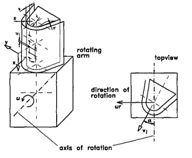
The purpose of the work by Prof. Mattern and D.K. Hennecke of TU Darmstadt was investigating the rotational effects [14, 18] on the temperature change due to a single row of rotating jets placing the curved area, corresponding to the cooling of the turbine blade [23]. Naphthalene sublimation process used for mass and heat transfer simulations was used in determining local heat transfer coefficients. The span wise average coefficients of heat transfer are measured with the help of local values and are adjusted in relation to heat transfer in a fixed system. The results were achieved with a wide variety of staggering angles, space between the jet hole plate, number of jet holes and the impingement region [14, 23]. The heat transfer in case of rotating system is reduced up to 40% of that in case of non-rotating system. Hence, the effect of rotation must be taken care for the exact estimation of the cooling pattern formed from impinging jets.
Figure 11. Graphic representation of test model configuration [8]
Geometric parameters and Jet Reynolds numbers accurately reflect the measurement features and multiplicity of the rotation number and the staggering angle in weight distribution. The following conclusions could be drawn from the experiments: (set up is given in Figure 11).
• At a = 0° (stagger angle), rotation affects the contour lines while on the other hand, for a = 90°, stagnation points are found to have been displaced radially [8, 14].
• At a = 0°, span wise jet hole spacing affects the variation of mass transfer. A change from r• = 4 to 2 has resulted in the reduction of transfer coefficients from s• = 6.1 to 30%. At a = 90°, t• is not much significant.
• While for aspect ratio 1:4, the difference in weight transfer due to rotation is in the same order of a = 0o and 90°, the maximum difference is determined. Average Sherwood numbers are span wise lessened by approximately 10% and 40% below coefficients in the non-rotating system. It depends on stagger angle as well and hence; it is negligible at a = 45° [13].
• The lower the jet-to-plate space, the more flexible the changes become. For s* = 6.1, mass transfers are reduced by 60% (by Ro = 0.02) and s* = 1 small order expansion 0% to 10% is withheld.
• The relative variability does not depend on the number of jet Reynolds. Here the different configurations are = 0° and e = 2. Here, the rotation results are fully enhanced and independent with a large Reynolds number (Re = 25,000).
• Due to the applied measurement techniques, only Coriolis force could cause the rotational effects [18] as determined in the current work. Therefore, the results obtained do not consider the rotation direction and the radial distance between the jets and the rotating axis.
Mainstream flow [24] of hot gas reaches the leading edge of the first rotor stage after exiting the combustor and directing through the leading holes of the nozzle guide. The temperature of these gases might exceed a whopping 1500oC, which is considerably higher than the allowable limits of metal temperatures. Thus, such heat loads need prudent cooling schemes which could be used at the rotor blade leading-edge portion [24]. The most common method of cooling is to apply a jet impact to the inner part of the cooling passage at its leading edge. The air that is present inside the gas turbine compressor is transmitted to the turbine blade channels that allow its cooling to take place internally. These channels present internally at the leading edges of the rotor blade make use of the cooling air for surface impingement of the inner part of the leading edge. Specially fitted nozzles on the leading-edge inner wall separates the leading channel from the other side curvy passages [24, 25]. Impingement occurs in the inner part of the leading-edge blade due to the flow from the neighbouring area forced by the use of jet holes. The important factors of design application [23, 25] of this type of cooling scheme considered are the shape and hole layout of the jet nozzle, the geometry of confinement chambers [25], the target surface and the jet-to target spacing and crossflow effects. As we know that the leading edge of such gas turbine blades fashion a design comprising a showerhead film cooling structure, studies have shown including holes on the target plates could enhance the film cooling significantly. In the presence of an initial cross flow, heat transfer is found out to be higher in case of jet impingement applied on effusion plate target than that applied on a solid plate [23]. The film cooling holes could reduce the crossflow effects.
8.1 CASE STUDY: 3D CAD modelling, designing and thermal-analysis of cooling of Gas radial-hole based turbine blade cooling
8.1.1 Problem statement
The operation of engines equipped with advanced gas turbine happens at high temperatures (1200–1500°C) so that its thermal efficiency and obtained power output could be substantially increased [23]. As the inside gas temperatures soar, the heat in turn transmitted to the blades will considerably increment subsequently. This might result in their thermal failure. Using the materials existing today, it’s technically not at all possible to seek higher ranges of temperature. Considering all the metallurgical limitations [24, 25], it is pivotal to have a provision for some cooling arrangement for these blades to gain control over and limit their metal temperature within allowable constraints. Thus, advancements and studies in technologies involving its cooling play a pivotal role in optimizing its thermal-efficiency and make sure that output power obtained from the engines equipped with advanced gas turbine is maximized.
8.1.2 Creating the cad model
Blade models (total four, one with no holes and three with changing numbers of holes i.e., five, nine and thirteen holes) are constructed in the CATIA (V5) design software [25]. The model having four holes were constructed in CATIA (V5) using coordinate systems for aerofoil, Figures 12, 13. Its values are as shown in table below and next table comprises of the mechanical-properties of N-155 & Chromium Steel, Table 1, 2.
Table 1. Aerofoil coordinates for gas turbine blades [26]
|
X |
Y |
Z |
|
48.5 |
0.5 |
0 |
|
45 |
3.95 |
0 |
|
38.2 |
8.77 |
0 |
|
26 |
13.6 |
0 |
|
21.1 |
14.9 |
0 |
|
16.18 |
15.5 |
0 |
|
3.2 |
13.5 |
0 |
|
2.6 |
17.3 |
0 |
|
5.82 |
21.5 |
0 |
|
10 |
25 |
0 |
|
14.8 |
26.6 |
0 |
|
22.9 |
25.3 |
0 |
|
24.5 |
24.7 |
0 |
|
28 |
23 |
0 |
|
33.4 |
19.5 |
0 |
|
38 |
15.3 |
0 |
|
42 |
10.9 |
0 |
|
45.4 |
6 |
0 |
|
48.5 |
0.5 |
0 |
Table 2. The mechanical-properties of N-155 & Chromium Steel [26]
|
Materials |
Chromium Steel |
N155 |
|
Density (kg/m3) |
7750 |
8249 |
|
Specific Heat (J/kgK) |
435 |
435 |
|
Thermal Conductivity (W/mK) |
24 |
20 |
Figure 12. Generic blade profile with holes [26]
Figure 13. Static temperature contour of blades with nine holes [26]
8.2 Results obtained
If the drilling of the holes is in a radial fashion [25] to make sure that the cooling air passes through cooling holes, the variation in the contours of the distribution of temperature is minimal inside the blade. It is obvious from the five holed blades that the temperature near the holes meant for cooling is lesser, but it could be improved towards the areas of the blade like its leading and trailing edge.
Figure 14. Static temperature contour of blade with thirteen staggered holes [26]
Figure 15. Static pressure contour of blade with nine holes [26]
Figure 16. Static pressure contour of blade with thirteen holes [26]
Observations say that in the blade containing nine holes, the distribution of temperature near leading-edge is low compared to the one containing only five holes. The distribution of temperature [25] is varied and the number of holes is subsequently increased. The temperature which is observed in these four modelled designs have indicated that the local temperature near the leading edge is lower than the blade containing thirteen holes. This decrease in the temperature contributes to low efficiency. Thus, the number of holes should be limited to thirteen, Figures 14, 15, 16 [25].
8.3 Inferences drawn
In this case study, the modelling and designing of a turbine blade is done using the CATIA (V5) software [23, 25]. These blades were designed by adding cooling holes in them. They were designed with five, nine and thirteen holes. The material being used presently for these blades is Chromium Steel. We in this study have replaced it with N155. Detailed thermal & structural simulations and analysis using CFD has been done using ANSYS. The leading-edge temperature is minimum and consequently, the rate of total heat transfer is highest for the blade containing thirteen holes for N-155 [25]. Temperature around the blade surface of the one with thirteen holes for N155 is observed to be minimum. Our observation indicates the temperatures of the gases that leave the trailing-edge being low which consequently results in decreased overall thermal efficiency of the gas turbine. Our results infer that the coefficient of heat-transfer and the Avg. Nusselt number (Nu) near these hole surfaces are almost uniform for every blade-material even with varying nos. of holes, with the coefficient of heat-transfer being high at the region of entrance.
Turbine Inlet Temperature could be extended to enhance thermal efficiency and gas discharge capacity. But it could lead to high temperatures and an efficient cooling system will ensure turbine components in safe condition. The leading edge of the blades is one of the most stressed parts thermally [18]. A system of multiple jets produced by the radial feeding channel that inserts into the inner surface of the leading edge is a widely used cooling method. Important geometric parameters of this cooling system are sharpness of the leading edge, distance between the jet nozzles, and surface of the leading edge and distribution of removal holes (location, number and angle). Flow field formed inside the leading edge is being described by the Jet Reynolds number. It is given by- [18]
$R e_{j}=\frac{U_{j} D_{h} \rho}{\mu}$ (1)
The flow field induced inside rotating blades is characterized by rotation number given by [18]:
$R o_{j}=\frac{D_{h}}{U_{j}}$ (2)
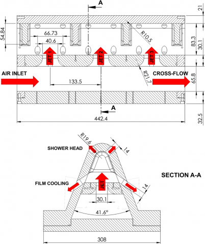
Both geometrical and boundary conditions are important for interaction of jet and LE geometry which affects the properties of flow and heat transfer. A 30 times scaled-up model of L.E. of turbine blade geometry is used which is based on a new cold bridge impingement cooling system. A sectional view depicts the flow of air inside the cooling system, Figure 17 [18].
Figure 17. Sectional view of LE model with dimensions in mm [18]
The parameters convective heat transfer and coolant flow are considered in the operation of a cold bridge system and as a result, the results are expressed according to the jet Nusselt number (Nuj = hDh/k). The steps of variation taken for Rej were 10,000 and 0.01 for rotation for conducting 64-point test matrix. Moreover, for each Rej–Roj couple, flow conditions across TIP, MID and HUB were verified. Because of the need of high rotational speed of the shaft and high mass flow rate of the gas, a maximum Rej = 30,000 was chosen as limit for cases at Roj = 0.05 and 70% crossflow. Overall area-averaged Nusselt’s number measured in static condition was obtained in a graph with relative uncertainty in measurement which agreed with various models available [18].
A comparison was done between two different working conditions- at Reynold number 10000 and 30000. Higher Nusselt values are present at the center of the leading edge and on both the regions of the lateral surfaces. The effect of cross flow on Nuj distribution, and consequently on the flow pattern of the jet is the change in shape of high Nuj areas across HUB and TIP, and various patterns of flow are observed internally. Since, the rate of flow of mass of the jet doesn’t vary significantly in different tests and only the crossflow which provides coolant to the jet varies, the variations in Nuj distribution could be considered due to variations in the jets formed only [18].
The jet bulk velocity could be calculated based on Reynold’s number formula. Then the effect of rotation was added to analyse heat transfer and flow field. Even when flowing across the HUB and the TIP, the jets apparently bend towards the suction side which from the above results show that there is no significant effect of rotation on Nusselt Distribution. The rotational effects become significant with decrease in crossflow mass flow rate. At Rej = 10000 and 30000, the circumferential distributions of Nuj,av shows that rotational effects are almost insignificant in HUB conditions (CR = 70%) whereas, in TIP configuration (CR = 10%) where high Nuj zones move towards the suction sides [18].
The Coriolis forces does not affect the plane directly due to the rotation and primary velocity component but the speed of the feed station is directly related to the rotating axis which could result in generation of gradient total pressure in the PS that could cause jet inclination on the other side. Other observations made from this experiment are bending and flattening of jet resulting in wider Nuj lateral peaks. Rotational implications on flow characteristics and Nuj distribution become significant with decreased rate of mass flow of the feeding duct at a given Roj value, possibly with increased rotation number Roc, of feeding duct, referring to increased effects of rotation on the jet impingement and jet generation zone itself [18].
9.1 Turbine blade cooling by PSP technique
Another paper [27] focusses on use of Pressure Sensitive Paints (PSP) method for turbine blade film cooling. Mass Transfer analogy is used to avoid conduction related issues in literature. There are several instances of it which could be seen in the literature published in the past. This method has been useful to study detailed effectiveness of turbine heat transfer and actual engine density ratios. The governing equations of heat transfer are considered here. Turbulent Lewis Number (LeT) plays a significant role in analyzing effectiveness of film cooling using mass transfer analogy. In cases, where it is practically taken as 1, highly turbulent gaseous flow field is needed which is well applicable to gas turbine vanes, blades and end walls due to high Reynolds’ number and other mechanisms which contribute in inducing turbulent field like periodic wakes, leakage vortices, film cooling jets, horse shoe vortices etc. [27]. But it is seen that even with film cooling, the flow around region of leading edge is laminar or sometimes intermittent. It poses a challenge for researchers to further investigate the cause [27].
Pressure Sensitive Paints could also be used for measurement of the external pressure on the painted surface. The paint emits red light when excited by blue light of the region. Oxygen quenching is a radiation-free path to the degenerate path. Intensity varies with partial pressure of oxygen around the paint. It is also dependent on temperature of the paint, so a calibration is needed for temperature and pressure of O2. The PSP is applied to the region of interest and even to the full body. Coolant to mainstream density effect ratio is simulated by several gases which are injected in between paint and surface via cooling holes and also helps in reducing oxygen concentration near the walls of the body. There are four tests conducted to determine cooling effectiveness. First, excitation LED light is switched off and intensity of background noise is estimated with a captured image in a dark room. In second test, the excitation light is turned on and camera is focused on the region of interest and certain images are captured. 3rd test involves setting the rate of coolant flow and mainstream at certain blowing ratio using air and capturing images. The final test consists a desired nitrogen coolant blowing ratio with a recording of averaged intensity. The uncertainties were accounted for optical issues, calibration, and displacement of model, sensitivity of PSP to temperature and certain limitations of Mass Transfer Analogy [27].
The Finite Element Analysis of steam cooling and air cooling of the foremost thermally stressed rotary engine (turbine) part power turbine blades of initial stage, and the cooling capacity was done [28]. The volumetric average blade temperature and the coefficient of heat transfer across the cooling channel and the cooling medium were considered because of the criterion of effectiveness of cooling [29, 30]. There's a nonstop want to extend the thermal efficiency of gas turbines that is accomplished chiefly by raising the gas temperature at inlet of the rotary engine. Future gas rotary engines operate at a temperature of over 1600oC at the turbine inlet. To enhance the operation of high-temperature components at such high parameters, limit coatings (thermal barrier) must be used [28] and advanced cooling systems. The value of the heat transfer coefficients obtained with a low pressure comply with the experimental and calculated values. The bestowed study calculates the cooling capacity of the primary stage rotary engine blade for various parameters of a cooling medium. Air and water vapour were used as cooling media for comparison. The criteria of cooling capacity chosen were the typical blade temperature and the coefficient of wall heat transfer. As shown within the study, steam is an economical agent compared to air when analyzed using identical pressure and temperature. When steam is used, the temperature of a blade gets reduced by 20-300℃, and therefore the coefficient of heat transfer between the steam and cooling channel is 10-30% greater than that for air [28, 29].
The concept of a rotary engine blade cooling system [28, 29] may be a multi-purpose optimization drawback consisting of constraints and complicated the design variables’ interaction. Evolutionary Computing techniques like Generalized Regression Genetic Algorithmic program (GRGA) [28] and also a mathematical model of the cooling system of practical rotary engine blades have been studied in this paper to formulate a strategy of design optimization. Even though the variable interaction is present, the process identifies variety of excellent possible styles chosen according to the designer’s preference. The analysis conjointly demonstrates the optimization capability of GRGA in case of the practical conditions. Real-life engineering style optimization issues [29] like design modification for weight optimization of aerospace structures or aesthetics improvement of vehicle body surface are encountered in industrial problems in contrast with the theoretical issues (test cases). In conjunction with qualitative problems, constraints, multiple objectives, and absence of earlier information, most of the real-life style optimization issues conjointly involve decision variable interactions. Despite its feasibility for practical problems, the lack of systematic analysis has infested the sector of variable interaction for a protracted time. During last 20 years, several analyses has been allotted through this space particularly within the domain of applied mathematics [28]. This has been additional increased currently with the expansion of Machine learning methods such as Fuzzy logic (FL), Neural Networks (NNs) and have expanded recently and added to the above field of study [30]. This paper focuses on coming up with a rotary engine blade cooling system employing a progressive evolutionary-based optimization algorithmic program, Generalized Regression Genetic algorithmic program (GRGA) [28, 29].
The paper is incontestable regarding optimization of a rotary engine blade cooling system style may be a difficult drawback thanks to the presence of advanced indivisible operation interactions among the decision variables. GRGA capability in advanced indivisible operate interaction was successfully established to spot a variety of best possible styles from that one might be chosen to support the preferences of a designer. The finite part analysis of a rotor and rotary engine blade is administered on brick and isoperimetric components [29, 30]. The thermal analysis of static modal is administered and also the results were just like the temperature encompasses an important impact on the general stresses within the rotary engine blade and the most elongation and temperatures are ascertained at the blade tip section and lowest elongations [29] and temperature variations are ascertained in the blade base as well as the temperature distribution of the blade profile in the most curved region. Most stresses and strains [30] are found on the blade length only in the blade region inside the rotor and the elongations in the Y-direction vary gradually from the different rotor axis parts.
The concave surface is seen to have enhanced heat transfer properties. This is because of the centrifugal effects which leads to reduction in boundary layer thickness causing unstable flow and generation of Taylor-Gortler Vortices which enhances the heat transfer rate due to enhanced mixing close to curved wall. A numerical study conducted on jet impingement cooling onto a concave leading edge of a turbine blade using k-ω SST model was found to be accurate and was in accordance with experimental results. The impingement cooling is strongly dependent on separation distance which also increases crossflow velocity which is not desirable though an increase in heat transfer rate is observed [31].
The results of experiment by Noot and Mattheij state that cooling of rotary engine blades in turbines is increased by providing the cooling ducts with ribs, especially turbulators. It's investigated however these ribs influence the heat transfer of the cooling air on the blades. A model is given to review this downside such it lends itself to a numerical approach. an in-depth discussion is given of the matter concerned. it's shown however the concepts area unit enforced in an exceedingly numerical code. The results of the simulations are assessed showing a way to check the standard of those cooling ducts [32].
Nowak et al. [33] presents the application of conjugate heat transfer prediction for optimization of a cooling system configuration. The search procedure used the evolutionary algorithmic rule. The analysis of a selected answer was done on the idea of CHT analyses among a cooled control surface. For the aim of this analysis a convectively cooled control surface was assumed and therefore the optimization consisted within the relocation and diameter changes of the cooling passages. The search procedure was run as a multi objective evolutionary algorithmic rule with use of the Pareto approach.
The designers are putting their efforts to enhance the power production and engine efficiency of today’s power plant turbines, the engineers are taking all the necessary steps to rise the TIT [34]. In some of the modern-day high-power producing units the temperature has took a rise from 1500 to 1750K. However, materials such as ceramics could raise this limit even further. Higher gas temperature could lead to increased blade temperature. This will have detrimental effects on service life. However, the people associated with the designing and maintenance process (industrial researchers) of turbo machines are continuously improving the computational techniques [35].
At the top where the hub and tip are situated of a turbine rotor / stator way, the passage is contrived by inter-linkage between side-wall boundary wall and stream-wise boundary wall. The region affected seems narrow but its influence on the performance and total aerodynamic system is not ignorable. In designing of a modern-day high-power producing turbine, it is very critical to know about the detailed three-dimensional passage area close to the turbine’s hub and tip. With the passage of time, considerable improvements are taking place in the field of computer science, now it has become considerably easier to compute three-dimensional flow and it became more and more useful. Some of the modern-day high-performance cooling techniques which are being used in the developed regions of the world have been discussed [34].
11.1 Internal cooling:
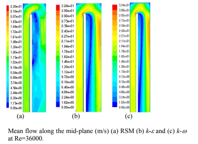
The Figure 18 shows stream-wise average velocity variation at mid-plane for Reynolds number, Re=36,000, where the flow disintegrates at 45º in the curved area of the contour [34, 35]. The process of the differentiation or separation of flow passage starts at around 45º, the point or area where these are supposed to be integrated takes a turn or displaces, for RSM this point is considered to be about 24 times of the curvature diameter.
For k-ε, the area or location of re-joining is about 14 times larger than the curvature diameter. Around 22 times the curvature diameter the secondary flow is slowly disappeared [35]. These mostly depends upon the Reynolds number, due to which the intensity of the flow alters causing different differentiation regions. The passage beyond the curve is immobile. All the three types which are discussed above portray a common variation in Nusselt number. Therefore, within the flow, disintegration of flow, impingement of flow and intense cross duct flow, this causes the thinning of the viscous sub-layer, and reduced its sensitivity to Reynolds numbers [34].
Figure 18. Mid-plane mean flow (m/s) for various models (a) RSM (b) k-ε (c) k- ω [35]
11.2 External surface film cooling
The film cooling [12] method and line markings of cylinder holes with integrated jet investigated by numerical considerations [16]. The demand for present gas turbines with a greater thrust-to - weight ratio results in a continuous improvement of the inlet and outlet, resulting in a higher thermal pressure on the turbine rotor. Thus, an enhanced proactive cooling arrangement is vital to separate the components of turbine from getting damaged due to overheating. Film cooling is a more systematic, structured and efficient technique which helps in the protection of the turbine from the hot gas passing by removing the internal cooling air through a hole or by inserting it into the outer parts of the blade. Since the removal of the cooling film [35] from the engine computer, the cooling film suspension must be well designed and properly designed to reduce the loss of thermal efficiency, Figure 19 [36].
Figure 19. Temperature distribution on different sections [36]
In the upcoming years the newer and easier techniques of cooling may become more accessible as the resources, technology and science develops [35]. The numerical study of flow field and heat transfer performance due to rotational effects on turbine blade cooling is studied using k-ω SST model (3-D) under constant heat flux supplied to leading edge and internal cooling takes place using 7 jets. The results are in accordance with the experimental results [36]. It has also been found that the presence of perforations damping cavities could significantly increase the effectiveness of film cooling blade and reduce adiabatic wall temperature at a constant flow rate of the coolant [37, 38].
With advancement in combustion technology and increasing power demand, the demand for turbines with higher efficiency is seen all over the world. For improving the thermodynamic efficiency of the turbine, it is preferred to operate the turbine with a higher inlet gas temperature. This brings the issue of turbine blade cooling into the mainstream discussion as only passing cooling air through the aerofoil is no longer sufficient. Hence, techniques such as vortex generators, impingement cooling, and film cooling among various other techniques have come to existence. These techniques enhance the coefficient of heat transfer and provide better cooling to serve the purpose.
However, limited number of works were done to understand the rotational effects on impingement cooling and pin-fin cooling. Also, the situation where the internal structure of aerofoil is sub-divided into “broken parts” to cause turbulence and enhance heat transfer is also yet to be fully understood. The regime of steam cooling and trailing edge cooling are also to be explored as the advanced cooling methods tend to heavily effect the leading and mid-section of the aerofoil. The results of the experiment on concave leading edge could be basis for further experiments including application of turbulators on inner curved surfaces [31].
The turbulator turning into a lot of pronounced because of further corrosion caused within the drilling method. this may be taken into consideration once standardization the drilling parameters. By an awfully delicate standardization of those parameters increased turbulator form will be obtained. the specified impact of the planning of this specific form is achieved; specifically, a 2 hundredth increase of cooling potency is found relative to turbulator form. To validate the numerical results, we'd like to check the results with some experimental knowledge. during this paper, experimental knowledge on heat transfer is bestowed for an even larger sort of turbulator shapes [32].
The possibility of untreated steam in an exceedingly closed cooling loop (CCL) will be analyzed, wherever heat removed throughout cooling may be regenerated in different plant zones. The results show the problem to permit an appropriate uniform distribution of blade temperature, whereas the employment of the opposite semi-closed cooling loop (SCL) choice with steam and air permits a lot of uniform blade cooling and therefore the risk to use steam and air within the same cooling blade theme. Globally, the air fluid cooling and therefore the steam fluid introduction represent 2 ordered steps within the progressive upgrading method of turbine blade cooling towards the 2 main goals; the reduction of fluid mass flowrate and more TIT will increase [21].
One of the foremost disadvantages of the evolutionary algorithmic rule in conjunction with the CHT analysis is their high computational value, therefore a parallel computing is needed. Ensuing step within the development of a cooling system optimization ought to be the appliance of the total CHT prediction, which might build the full method a lot of reliable. Also, within the future work the flow ought to be analyzed a lot precisely: together with a lot of layers within the spanwise direction and hub and tip physical phenomenon, mistreatment finer grids within the holes, analyzing the various turbulent models, calibrating a transition model. these days it's a task for the only case CHT analysis and so extension of the optimization procedure may be done stepwise, counting on the computer power.
|
TIT |
Turbine Inlet Temperature |
|
PSP |
Pressure Sensitive Paints |
|
EC |
Evolutionary Computing |
|
NN |
Neural Networks |
|
FL |
Fuzzy Logic |
|
GRGA |
Generalised Regression Genetic Algorithm Program |
|
OCSC |
Open Circuit Steam Cooling |
|
CLSC |
Closed Loop Steam Cooling |
|
LE |
Leading Edge |
|
Nu |
Nusselt’s Number |
|
CFD |
Computational Fluid Dynamics |
|
LeT |
Turbulent Lewis Number |
[1] https://ourworldindata.org/grapher/share-electricity-fossil-fuels?tab=chart&stackMode=absolute&time=earliest..latest®ion=World, accessed on 17 March 2021.
[2] Nourin, F.N., Amano, R.S. (2021). Review of gas turbine internal cooling improvement technology. International Journal of Energy Resources Technology, 143(8): 080801. https://doi.org/10.1115/1.4048865
[3] IEA. (2020). World Energy Outlook 2020, IEA, Paris. https://www.iea.org/reports/world-energy-outlook-2020.
[4] Xu, L., Wang, W., Gao, T., Shi, X., Gao, J., Liang, W. (2014). Experimental study on cooling performance of a steam-cooled turbine blade with five internal cooling smooth channels. Experimental Thermal and Fluid Science, 58: 180-187. https://doi.org/10.1016/j.expthermflusci.2014.07.004
[5] Fan, X., Li, L., Zou, J., Zhou, Y. (2019). Cooling methods for gas turbine blade leading edge: Comparative study on impingement cooling, vortex cooling and double vortex cooling. International Communications in Heat and Mass Transfer, 100: 133-145. https://doi.org/10.1016/j.icheatmasstransfer.2018.12.017
[6] Najjar, Y.S., Alghamdi, A.S., Al-Beirutty, M.H. (2004). Comparative performance of combined gas turbine systems under three different blade cooling schemes. Applied Thermal Engineering, 24(13): 1919-1934. https://doi.org/10.1016/j.applthermaleng.2003.12.002
[7] Fan, X., Du, C., Li, L., Li, S. (2017). Numerical simulation on effects of film hole geometry and mass flow on vortex cooling behavior for gas turbine blade leading edge. Applied Thermal Engineering, 112: 472-483. https://doi.org/10.1016/j.applthermaleng.2016.10.059
[8] Adawale, A., Biyani, S., Pawar, A., Naidu, M. (2017). Fatigue life comparison of gas turbine blade with and without cooling effect. International Conference on Ideas. Impact and Innovation in Mechanical Engineering (ICIIIME 2017), pp. 1205-1212.
[9] Inozemtsev, A.A., Tikhonov, A.S., Sendyurev, C.I., Samokhvalov, N.Y. (2013). Achieving better cooling of turbine blades using numerical simulation methods. Thermal Engineering, 60(2): 92-97. https://doi.org/10.1134/S0040601513020031
[10] Pudake, P., Elgandelwar, A.M., Lele, M.M. (2017). Gas turbine blade cooling technology–a case study. International Journal of Current Engineering and Technology, 7: 195-201.
[11] Al Ali, A.R., Janajreh, I. (2015). Numerical simulation of turbine blade cooling via jet impingement. Energy Procedia, 75: 3220-3229.
[12] Xue, S., Ng, W.F. (2018). Turbine blade tip external cooling technologies. Aerospace, 5(3): 90. https://doi.org/10.3390/aerospace5030090
[13] Patil, P.S., Borse, S.L. (2018). Recent studies in internal cooling of gas turbine blade: A review. International Journal of Applied Engineering Research, 13(9): 7131-7141.
[14] Han, J.C. (2004). Recent studies in turbine blade cooling. International Journal of Rotating Machinery, 10(6): 443-457. https://doi.org/10.1155/S1023621X04000442
[15] Gaikwad, S.S., Sonawane, C.R. (2014). Numerical simulation of gas turbine blade cooling for enhancement of heat transfer of the blade tip. IJRET: International Journal of Research in Engineering and Technology, 3(9): 35-41.
[16] Dewangan, D., Verma, A.K. (2016). Numerical investigation of turbine blade cooling passage with v-shape truncated and continuous ribs. IJESRT, 5(7): 36-48.
[17] Kumar, S. (2012). Investigation of heat transfer and flow using ribs within gas turbine blade cooling passage: experimental and hybrid LES/RANS modeling. Theses and Dissertations.
[18] Massini, D., Burberi, E., Carcasci, C., Cocchi, L., Facchini, B., Armellini, A., Casarsa, L., Furlani, L. (2017). Effect of rotation on a gas turbine blade internal cooling system: experimental investigation. Journal of Engineering for Gas Turbines and Power, 139(10): 101902. https://doi.org/10.1115/1.4036576
[19] Mishra, S. (2018). Energy and exergy analysis of air-film cooled gas turbine cycle: effect of radiative heat transfer on blade coolant requirement. Applied Thermal Engineering, 129: 1403-1413. https://doi.org/10.1016/j.applthermaleng.2017.10.128
[20] Mishra, S., Sharma, A., Kumari, A. (2020). Response surface methodology based optimization of air-film blade cooled gas turbine cycle for thermal performance prediction. Applied Thermal Engineering, 164: 114425. https://doi.org/10.1016/j.applthermaleng.2019.114425
[21] Facchini, B., Ferrara, G., Innocenti, L. (2000). Blade cooling improvement for heavy duty gas turbine: the air coolant temperature reduction and the introduction of steam and mixed steam/air cooling. International Journal of Thermal Sciences, 39(1): 74-84. https://doi.org/10.1016/S1290-0729(00)00194-X
[22] Safi, A., Hamdan, M.O., Elnajjar, E. (2020). Numerical investigation on the effect of rotation on impingement cooling of the gas turbine leading edge. Alexandria Engineering Journal, 59(5): 3781-3797. https://doi.org/10.1016/j.aej.2020.06.035
[23] Han, J.C. (2006). Turbine blade cooling studies at Texas A&M University: 1980-2004. Journal of Thermophysics and Heat Transfer, 20(2): 161-187. https://doi.org/10.2514/1.15403
[24] Begum, F., Reddy, V.R., Ramanjaneyulu, S. (2017). Design and thermal analysis of cooling of Gas turbine blade through radial holes. Materials Today: Proceedings, 4(8): 7714-7722. https://doi.org/10.1016/j.matpr.2017.07.106
[25] Teja, T.R., Chaitanya, S.K. (2013). Case study on turbine blade internal cooling. International Journal of Engineering Research & Technology (IJERT), 2(3): 1-5.
[26] Singh, P., Shukla, O.P. (2016). Heat transfer analysis of gas turbine rotor blade through staggered holes using CFD. International Journal of Engineering Research and General Science, 4(2).
[27] Han, J.C., Rallabandi, A. (2010). Turbine blade film cooling using PSP technique. Frontiers in Heat and Mass Transfer (FHMT), 1(1). http://dx.doi.org/10.5098/hmt.v1.1.3001
[28] Roy, R., Tiwari, A., Corbett, J. (2003). Designing a turbine blade cooling system using a generalised regression genetic algorithm. CIRP Annals, 52(1): 415-418. https://doi.org/10.1016/S0007-8506(07)60614-3
[29] Moskalenko, A.B., Kozhevnikov, A.I. (2016). Estimation of gas turbine blades cooling efficiency. Procedia Engineering, 150: 61-67. https://doi.org/10.1016/j.proeng.2016.06.716
[30] Kumar, V.V., Narayana, R.L., Srinivas, C.H. (2014). Design and analysis of gas turbine blade by potential flow approach. Int. Journal of Engineering Research and Applications, 4(1): 187-192.
[31] Forster, M., Weigand, B. (2021). Experimental and numerical investigation of jet impingement cooling onto a concave leading edge of a generic gas turbine blade. International Journal of Thermal Sciences, 164: 106862. https://doi.org/10.1016/j.ijthermalsci.2021.106862
[32] Noot, M.J., Mattheij, R.M.M. (2000). Numerical analysis of turbine blade cooling ducts. Mathematical and Computer Modelling, 31(1): 77-98. https://doi.org/10.1016/S0895-7177(99)00217-4
[33] Nowak, G., Wróblewski, W., Nowak, I. (2012). Convective cooling optimization of a blade for a supercritical steam turbine. International Journal of Heat and Mass Transfer, 55(17-18): 4511-4520. https://doi.org/10.1016/j.ijheatmasstransfer.2012.03.072
[34] Cerri, G., Giovannelli, A., Battisti, L., Fedrizzi, R. (2007). Advances in effusive cooling techniques of gas turbines. Applied Thermal Engineering, 27(4): 692-698. https://doi.org/10.1016/j.applthermaleng.2006.10.012
[35] Acharya, S., Kanani, Y. (2017). Advances in film cooling heat transfer. In Advances in Heat Transfer, 49: 91-156. https://doi.org/10.1016/bs.aiht.2017.10.001
[36] Mohammadi-Ahmar, A., Mohammadi, A., Raisee, M. (2020). Efficient uncertainty quantification of turbine blade leading edge film cooling using bi-fidelity combination of compressed sensing and Kriging. International Journal of Heat and Mass Transfer, 162: 120360. https://doi.org/10.1016/j.ijheatmasstransfer.2020.120360
[37] Kovalnogov, V.N., Fedorov, R.V., Generalov, D.A. (2015). Modeling and development of cooling technology of turbine engine blades. Int. Rev. Mech. Eng., 9(4): 331-335.
[38] Amano, R.S. (2008). Advances in gas turbine blade cooling technology. Advanced Computational Methods and Experiments in Heat Transfer X, B. Sunden and CA Brebbia, eds., WIT Press, Southampton, UK.