Fei Gao | Shuai Lv | Changyuan Zhang | Peng Zhang | Zhenggang Guo | Qinyi Ma | Xu Zhang*
© 2020 IIETA. This article is published by IIETA and is licensed under the CC BY 4.0 license (http://creativecommons.org/licenses/by/4.0/).
OPEN ACCESS
During pipe jacking in unstable coal rock formation, it is difficult to ensure the stability of the workface and the structural safety of the equipment. To solve the problem, this paper establishes a numerical model for the rock-breaking and slag discharge of pipe jacking machine (PJM) with different tunneling parameters, and numerically analyzes the variations in the flow rate and speed of slags, and the stress and deformation of cutterhead, at different cutterhead speeds (1.0-4.0r/min) and jacking speeds (0.5-4.0mm/s). Based on the simulation results, the authors discussed how different tunneling parameters affect the tunneling safety. The simulation results highlight the importance of the matching between cutterhead speed and jacking speed to tunneling safety. As the jacking speed increased, the load of the cutterhead increased significantly, which may cause the cutter to wear. At the jacking speed of 4.0mm/s, the equivalent stress and deformation of cutterhead peaked at 397.43MPa, and 10.73mm, respectively. Excessive jacking speed may result in accidents, such as deformation and structural fracture of cutterhead, posing a serious threat to the structural safety of cutterhead. As the cutterhead speed increased from 1.0r/min to 4.0r/min, the mean axial speed of slags dropped by 68%, and the slag flow rate declined by 76%, due to the rapid discharge of slags from the cabin. In this case, the slag volume in the cabin cannot provide sufficient support to the workface rock, and the risk of collapse soars during the tunneling in unstable formation. In addition, an excessive cutterhead speed increased tunneling energy consumption and aggravated the wear of the cutterhead. The research results promote the setting of control parameters for the safe pipe jacking in unstable coal rock formation.
pipe jacking machine (PJM), tunneling safety, coal rock formation, discrete-element method (DEM)
Out of the various disasters in coalmines, roadway destruction and blockage are the primary reasons why underground personnel fail to escape or receive supply and treatment in time, and even die from suffocation. The key to reducing casualties in coalmine disasters is to excavate rescue channels quickly. During the rapid excavation, however, any improper operation will lead to secondary disasters, owing to the poor formation stability in the disaster-stricken coalmine.
Conventional tunneling methods, which rely on shield tunneling machine [1], large-diameter drilling machine [2, 3], or shaft [4-6], face common problems like slow rock-breaking speed, large equipment size, and high operating cost, failing to set up rescue channels rapidly. Pipe jacking machine (PJM), an engineering equipment to lay small-diameter pipes in complex stratum, boasts the ability to tunnel quickly into coal rock stratum [7, 8]. During pipe jacking, the workface is supported and protected by a shield. Therefore, PJM achieves better tunneling safety than other tunneling machines [9]. Currently, PJM development has become a hotspot in the field of underground coalmine rescue [10].
During PJM tunneling in collapsed coal seams, the main safety concerns are the stability of tunneling and the structural strength of the cutterhead. On the one hand, the workface stability depends on the slag discharge performance of the cutterhead. If the control parameters are improper, the unstable coal rock formation might collapse again. On the other hand, the cutterhead will face large resistance in the tunneling and rotation directions, under improper control parameters. In this case, the cutterhead will suffer from large deformation and structural damage. To build rescue channels in coalmine, it is important to study the key factors affecting the safety of PJM tunneling, and establish a control strategy that fully consider both safety and speed.
For many years, the rock-breaking capacity and tunneling performance of tunneling machines have been investigated from multiple angles. On the rock-breaking mechanism of cutters, Jeong et al. [11] evaluated the machinability of different rocks, constructed a cutting force prediction model for tunnel boring machine (TBM), and presented a method to predict the cutting performance and optimize the structure of TBM cutter. On the design and layout of cutterhead, Sun et al. [12] proposed an adaptive design method for cutter layout based on genetic algorithm (GA), in view of cutter life and wear principle. Through cutting tests, Sun et al. [13] established a cutter optimization management method, in the light of cutter life and tunneling efficiency.
On the tunneling performance of cutterhead, Xia et al. [14] built up a numerical calculation model for the slag removal process of TBM cutterhead, which considers the generation, falling, and cutterhead collision of slags while tunneling, and summarized the how the aspect ratio and opening angle of the slag groove affect the slag discharge of the cutterhead. Huo et al. [15] established a PFC3D discrete-element model for the slag discharge of the cutterhead, examined the effects of the number and size of slag grooves on slag flowability, and optimized the layout of slag grooves for TBM cutterhead. Yang et al. [16] simulated the slag discharge process by discrete-element method (DEM), constructed a numerical model for the falling, shoveling, and discharge of slags with different shapes and gradations on the cutterhead, explored how the cutterhead’s slag discharge performance is affected by multiple factors (e.g., hob group, shovel structure, shovel height, and shovel width), and verified the reliability of the numerical model through reduced-scale tests on slag discharge. Taking viscous particles as the material model, Park et al. [17] performed discrete-element simulation of the transport capacity of screw conveyors with different inclination angles. Geng et al. [18] numerically studied the slag transport process of TBM cutterhead, and evaluated the impacts of the following factors on slag transport capacity and stability by the DEM: number and size of slag grooves, shape of slags, as well as the diameter and number of revolutions of cutterhead.
To sum up, many numerical simulations have been conducted on various factors that affect the tunneling performance, slag discharge, and structural strength of tunneling machines, laying a solid theoretical basis for our research. But there are several deficiencies with the existing research: little attention was paid to the tunneling performance of the machines in fractured coal rock formation. Unlike normal rock formations, the coal rock formation in disaster-stricken coalmines is very unstable. To ensure the rapid and safe tunneling of the PJM, it is necessary to explore deep into the breaking of coal rock and the flow of slag, and analyze their impacts on tunneling safety.
This paper couples DEM with finite-element method (FEM) to simulate the tunneling process of PJM cutterhead in coal rock formation. Based on the simulation data, the authors examined the flow features of slags and force features of cutterhead, and analyzed the influence of cutterhead speed and jacking speed on workface stability and equipment structural safety. The research findings provide a reference for optimizing PJM working parameters in complex environment.
2.1 Particle models
The discrete-element software EDEM was chosen to simulate the cutting, transport, and discharge of coal rock under the tunneling of PJM cutterhead. Before breaking, workface rock is a continuous cohesive material. Once broken, the slags can be viewed as a loose material with discrete properties [19, 20]. Therefore, the continuity of the coal rock before breaking was simulated by the bonding model, while the contact force, displacement, and relative motion between rock particles after breaking were simulated by the linear contact model and sliding model.
2.1.1 Linear contact model
In the linear contact model, the relationships of particle displacement with normal contact force, and tangential contact force can be expressed as:
$\left\{ \begin{matrix} F_{\text{i}}^{n}={{\text{K}}^{\text{n}}}{{U}^{n}}{{n}_{i}} \\ \Delta F_{i}^{s}=-{{K}^{s}}\Delta U_{i}^{s} \\\end{matrix} \right.$ (1)
where, $F_{i}^{n}$ and $F_{i}^{s}$ are the normal and tangential contact forces of particle i, respectively; $U^{n}$ is the normal displacement increment; $U_{i}^{s}$ is the tangential displacement increment of particle i; $K^{n}$ and $K^{s}$ are normal and tangential contact stiffness, respectively; $n_{i}$ is the unit normal vector.
The normal contact stiffness can be expressed as:
${{K}^{n}}=\frac{K_{n}^{\left[ A \right]}K_{n}^{\left[ B \right]}}{K_{n}^{\left[ A \right]}+K_{n}^{\left[ B \right]}}$ (2)
where, $K_{n}^{[A]} \text { and } K_{n}^{[B]}$ are the normal stiffness of two particles in contact with each other.
The tangential contact stiffness can be expressed as:
${{K}^{s}}=\frac{K_{s}^{\left[ A \right]}K_{s}^{\left[ B \right]}}{K_{s}^{\left[ A \right]}+K_{s}^{\left[ B \right]}}$ (3)
where, $K_{s}^{[A]}$ and $K_{s}^{[B]}$ are the tangential stiffness of two particles in contact with each other.
2.1.2 Sliding model
The slip between particles mainly hinges on the tangential force between particles and the maximum static friction. Sliding occurs when the tangential force exceeds the maximum static friction. Let μ be the smallest coefficient of friction between particles. Then, the maximum static friction can be expressed as:
$F_{\max }^{s}=\mu \left| F_{i}^{n} \right|$ (4)
Two particles slide relative to each other, when the tangential contact force satisfies $\left|F_{i}^{S}\right|>F_{\max }^{S}$.
2.1.3 Bonding model
The bonding model mainly defines the bonding between particles. This paper primarily studies the particle transport performance in the cylinder. Therefore, the normal and tangential bonding strengths between particles only need to maintain the workface as a static structure throughout the tunneling. The criterion of bonding failure between particles can be expressed as:
$\left\{ \begin{matrix} F_{c}^{n}={{R}_{n}} \\ F_{c}^{s}={{R}_{s}} \\\end{matrix} \right.$ (5)
where, $R_{n}$ and $R_{s}$ are the normal and tangential bonding strengths of particles, respectively.
2.2 Model parameters
To describe the cohesion and dispersion of the coal rock before and after breaking, it is necessary to measure the basic physical parameters of the coal rock, and calibrate the parameters of the coal rock particle models. The main physical parameters of the coal rock are presented in Table 1.
Table 1. Main physical parameters of the coal rock
|
Parameter |
Normal stress (MPa) |
Tangential stress (MPa) |
Static friction coefficient |
Dynamic friction coefficient |
||
|
Coal-coal |
Coal-steel |
Coal-coal |
Coal-steel |
|||
|
Value |
17.71 |
8.162 |
0.9 |
0.7 |
0.9 |
0.7 |
The following assumptions were made before modeling the workface rock: (1) The PJM tunnels horizontally, that is, the workface model is perpendicular to the PJM model, without considering the impact of coal seam inclination; (2) The workface model encompasses spherical particles of equal size with a diameter of 30mm; as the workface breaks, the forces between coal particles are of the same magnitude; (3) The workface is 150mm tall, 800mm wide, and 3,000mm long.
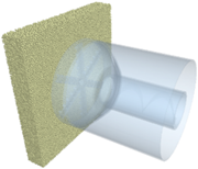
The PJM mainly consists of a shell, a cutterhead, a cabin, and a screw conveyor. The spoke-type cutterhead has multiple spokes. The cutters are evenly distributed on both sides of each spoke. On the three-dimensional (3D) modeling software SolidWorks, the PJM was modelled after suitable simplifications, and imported to EDEM. Table 2 lists the main structural parameters of the PJM. The material of the machine was defined as steel with density of 7.85×10³kg/m3, elastic modulus of 4.25GPa, and Poisson’s ratio of 0.23. The simulation model for PJM tunneling is made up of workface model and PJM model (Figure 1).
Table 2. Main structural parameters of the PJM
|
Parameter |
Value |
|
Cutterhead diameter |
1,630mm |
|
Opening rate |
60% |
|
Cutterhead thickness |
40mm |
|
Inner diameter of screw conveyor |
500mm |
|
Length of screw conveyor |
3,665mm |
|
Pitch of screw conveyor |
400mm |
Figure 1. Simulation model of tunneling process
2.3 Simulation schemes
The tunneling principle of the PJM can be summarized as follows: The cutterhead is pushed forward by the hydraulic cylinders, which are uniformly distributed in the circumferential direction, while rotated with the screw conveyor under the action of multiple motors. Then, the workface rock is cut by the cutters on the cutterhead. The broken slags fall into the cabin behind through the opening of the cutterhead, and transported to the rear by the screw conveyor. The PJM tunneling state is mainly affected by cutterhead speed and jacking speed.
According to the data collected from PJM tunneling sites, the control parameters of the machine for coalmine tunneling were defined in the following ranges: cutterhead speed (1.0-4.0r/min), jacking speed (0.5-4.0mm/s). Then, eight simulation schemes were established as shown in Table 3.
Table 3. Simulation schemes
|
No. |
Fixed condition |
Test condition |
|
|
1 |
Cutterhead speed 1.0r/min |
Jacking speed (mm/s) |
0.5 |
|
2 |
1.0 |
||
|
3 |
2.0 |
||
|
4 |
4.0 |
||
|
5 |
Jacking speed 0.5mm/s |
Cutterhead speed (r/min) |
1.0 |
|
6 |
2.0 |
||
|
7 |
3.0 |
||
|
8 |
4.0 |
||
Next, the influence of control parameters on tunneling stability and structural safety were analyzed through both DEM and SEM. After the PJM reached a stable cutting state, the flow rate and mean axial speed of slags at the opening in the front of the cutterhead were extracted from the DEM analysis results; the maximum stress and maximum deformation of cutterhead were extracted from the SEM analysis results. Among them, the flow rate of slags represents the tunneling efficiency of the cutterhead, the axial speed of slags represents the efficiency of slag discharge, and the maximum stress and maximum deformation of cutterhead represent structural strength.
3.1 Simulation results
Simulations were carried out under the parameter settings in Table 3. The simulation results of the eight schemes are recorded in Table 4.
Table 4. Simulation results
|
No. |
Mean axial speed of slags (mm/s) |
Flow rate of slags (kg/s) |
Maximum equivalent stress of cutterhead (MPa) |
Maximum deformation of cutterhead (mm) |
|
1 |
0.34 |
0.56 |
81.9 |
1.69 |
|
2 |
0.86 |
1.01 |
100.90 |
2.35 |
|
3 |
1.70 |
2.79 |
233.92 |
5.14 |
|
4 |
3.24 |
3.72 |
397.43 |
10.73 |
|
5 |
0.34 |
0.56 |
81.90 |
1.69 |
|
6 |
0.28 |
0.31 |
109.52 |
2.13 |
|
7 |
0.13 |
0.20 |
116.37 |
2.31 |
|
8 |
0.11 |
0.13 |
139.66 |
2.43 |
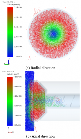
Figure 2 is the cloud maps of the slag flow speed under scheme 1 (cutterhead speed 1.0 r/min, jacking speed 1.0 mm/s). As shown in Figure 2(a), the fallen slags moved circularly on the cutterhead, under the action of gravity and the cutterhead. The particles moved faster on the peripheral, while those moved slower near the center. Thus, the particles in the center of the cutterhead have poor flowability, and might block the rotation of the cutterhead during tunneling.
Figure 2. Cloud maps of the slag flow speed under scheme 1
As shown in Figure 2(b), when the cutterhead approached the workface, the workface rock fell off under the cutting action of the hobs, and continuous entered the cabin through the opening of the cutterhead, before being discharged by the screw conveyor. The particles had the fastest speed upon the entry to the cabin through the cutterhead opening. After entering the cabin, the particles flowed toward the inlet of the screw conveyor. During this process, the axial speed of the particles continued to decrease. Upon entering the screw conveyor, the axial speed of the particles basically stabilized, while the particles were transported to the rear of the machine at a uniform speed. From the mean particle speeds in three directions, it is obvious that the particles moved in a spiral trajectory within the cabin during slag discharge, where the axial speed was faster than radial speed.
Figure 3 provides the cloud maps of cutterhead stress and deformation under scheme 1. As shown in Figure 3(a), the stress gradually increased from the center to the edge of the cutterhead, suggesting that the linear speed, impact, and cutting resistance of the cutterhead increases with the proximity to the edge.
Figure 3. Cloud maps of cutterhead stress and deformation under scheme 1
As shown in Figure 3(b), the cutterhead deformation gradually increased from the edge to the center. This is because the cutting effect is poorer at the center than on the edge, for the relatively low linear speed at the center. The protrusion at the middle of workface rock causes extrusion deformation to the center of the cutterhead surface.
3.2 Influence of jacking speed on tunneling performance
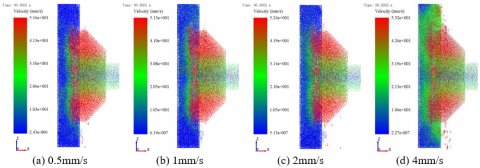
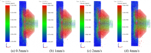
Figure 4 displays the cloud maps for the axial speeds of coal rock particles at different jacking speeds, while cutterhead speed is fixed at 1.0 r/min. As the jacking speed rose from 0.05mm/s to 4.0mm/s, the particle flow rate increased from 0.56kg/s to 3.72 kg/s, while the mean axial speed of particles climbed up from 0.34mm/s to 3.24mm/s. Thus, both tunneling and slag discharge of the PJM improve with the growing jacking speed. However, the slag discharge efficiency is restricted by the low cutterhead speed. As the jacking speed increases, the tunneling efficiency will be affected, for too many slags are accumulated in the cabin. If the jacking speed is too fast, the slags that cannot enter the cabin through the opening at the front of the cutterhead will rotate with the cutterhead, increasing the load of the cutterhead and weakening the rock-breaking effect of cutters.
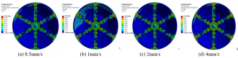
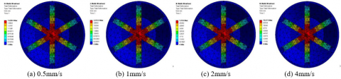
Figures 5 and 6 show the stress and deformation distributions of the front face of the cutterhead under different jacking speeds, respectively. It can be seen that the stress and deformation of the cutterhead both increased with the jacking speed. As the jacking speed rose from 0.05mm/s to 4.0mm/s, the maximum equivalent stress of the cutterhead increased from 81.9MPa to 397.43MPa, while the maximum deformation of the cutterhead increased from 1.69mm to 10.73mm. Under a large force, the cutterhead may easily suffer from various damages. For example, the prolonged exposure to excessive thrust will induce excessive wear on the surface and cutters, cracking of components, and even blade breakage of the cutterhead; instantaneous large thrust will bring serious accidents, such as large deformation of cutterhead structure, and spoke breakage. Therefore, the structural safety of the cutterhead is greatly threatened by an excessive jacking speed, when the cutterhead speed is slow.
Figure 4. Cloud maps of slag speeds at different jacking speeds
Figure 5. Cloud maps of cutterhead stresses at different jacking speeds
Figure 6. Cloud maps of cutterhead deformations at different jacking speeds
3.3 Influence of cutterhead speed on tunneling performance
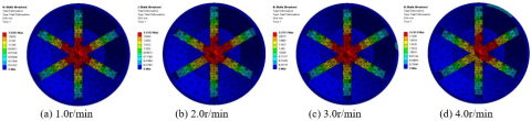
Figure 7 displays the cloud maps for the axial speeds of coal rock particles at different cutterhead speeds, while jacking speed is fixed at 0.05mm/s. As the cutterhead speed rose from 1.0 r/min to 4.0 r/min, the particle flow rate decreased from 0.56 kg/s to 0.13 kg/s, and the mean axial speed of the particles dropped from 0.34 mm/s to 0.11 mm/s. At the slow jacking speed, a few slags are cut by the cutterhead. In this case, any increase of cutterhead speed will discharge the slags from the cabin at a faster speed. When there are too few slags in the cabin, the cabin pressure will not be sufficient to support the workface rock. In the unstable underground environment of the disaster-stricken coalmine, the PJM tunneling safety will be undermined, if the workface rock collapses. As the cutterhead speed rose from 1.0 r/min to 4.0 r/min, the maximum speed of the particles surged from 5.16mm/s to 20.6mm/s. This means the radial speed of slags increases with cutterhead speed. However, if the cutterhead speed is too fast, the slags at the front and in the cabin of the cutterhead will rotate with the cutterhead, which pushes up the energy consumption of tunneling, as well as the wear of the cutterhead.
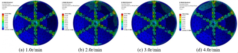
Figures 8 and 9 show the stress and deformation distributions of the front face of the cutterhead under different cutterhead speeds, respectively. As cutterhead speed rose from 1.0 r/min to 4.0 r/min, the maximum equivalent stress and maximum deformation of the cutterhead increased from 81.9MPa to 139.66MPa, and from 1.69mm to 2.43mm, respectively. Overall, the cutterhead stress increases with cutterhead speed. Compared with jacking speed, cutterhead speed exerts a small impact on the structural strength of cutterhead.
Figure 7. Cloud maps of slag speeds at different cutterhead speeds
Figure 8. Cloud maps of cutterhead stresses at different cutterhead speeds
Figure 9. Cloud maps of cutterhead deformations at different cutterhead speeds
This paper combines FEM with DEM to simulate the PJM tunneling in coal rock formation, and analyzes the influences of cutterhead speed and jacking speed on PJM performance. In addition, the PJM control parameters were optimized from the perspective of tunneling safety. The simulation results show that: the slags stripped off the workface rotated circularly on the rotating cutterhead; the slowest slag flow rate was observed at the center of the cutterhead, a sign of poor flowability; the slow-moving slags could easily block the rotation of the cutterhead, and cause excessive deformation at the center of the cutterhead. To improve the slag flowability at this position, the opening at the center of cutterhead should be widened or more cutters should be arranged at this place. It was also observed that both flow rate and mean axial speed of slags increased with jacking speed, which benefits the efficiency of tunneling and slag discharge. However, an excessive jacking speed will apply too much load on the cutterhead, which in turn weakens the cutting effect, and induces accidents that severely threaten structural safety of cutterhead (e.g., cutterhead damage, cutterhead deformation, and structural breakage). Furthermore, the increase of cutterhead speed promotes the efficiency of slag discharge, but increases the mean radial speed of the slags. The rising slag speed will push up the energy consumption of tunneling, as well as the wear of the cutterhead. If the cutterhead speed is too fast, the slags in the cabin could not sufficiently support workface rock, undermining the tunneling safety in unstable coal rock formation. The research findings provide theoretical support to PJM tunneling into unstable coal rock formation.
This work is grateful to the financial supports from National Key R&D Program of China (Grant No.: 2018YFC0808205) and Liaoning Natural Science Foundation (Grant No.: 2019ZD0123).
[1] Geng, Q., Wei, Z., Meng, H., Macias, F.J., Bruland, A. (2016). Free-face-assisted rock breaking method based on the multi-stage tunnel boring machine (TBM) cutterhead. Rock Mechanics and Rock Engineering, 49(11): 4459-4472. https://doi.org/10.1007/s00603-016-1053-6
[2] D’Auteuil, A., McTavish, S., Raeesi, A. (2020). A new large-scale dynamic rig to evaluate rain-wind induced vibrations on stay cables: Design and commissioning. Journal of Wind Engineering and Industrial Aerodynamics, 206: 104334. https://doi.org/10.1016/j.jweia.2020.104334
[3] Yang, J., Wang, X. (2017). Study and development of a linear drilling-type pre-cutting machine for tunnels in soft rock. Modern Tunnelling Technology, 54(4): 213-218. https://doi.org/10.13807/j.cnki.mtt.2017.04.029
[4] Huang, J., Wang, H., Ji, G., Zhao, Fei., Ming, R. Hao, Y. (2018). The rock breaking mechanism of ultrasonic high frequency rotary-percussive drilling technology. Petroleum Drilling Techniques, 46(4): 23-29. https://doi.org/10.11911/syztjs.2018097
[5] Walls, E.J., Joughin, W.C., Paetzold, H.D. (2019). Geotechnical data analysis to select a feasible method for development of a long axis, large diameter vertical ventilation shaft. Journal of the Southern African Institute of Mining and Metallurgy, 119(4): 377-384. https://doi.org/10.17159/2411-9717/17/390/2019
[6] Kim, D., Jeong, S., Park, J. (2020). Analysis on shaft resistance of the steel pipe prebored and precast piles based on field load-transfer curves and finite element method. Soils and Foundations, 60(2): 478-495. https://doi.org/10.1016/j.sandf.2020.03.011
[7] Shimada, H., Sasaoka, T., Hamanaka, A., Sato, T., Matsumoto, F. (2017). Application of pipe jacking technology into ASEAN countries. NASTT's No-Dig Show and ISTT's 35th International No-Dig - National Harbor, United States.
[8] Maehara, K., Shimada, H., Sasaoka, T., Hamanaka, A., Matsumoto, F., Morita, T. (2019). Fundamental study on application of underpinning method using pipe jacking by means of numerical simulation. 5th ISRM Young Scholars' Symposium on Rock Mechanics and International Symposium on Rock Engineering for Innovative Future, Okinawa, Japan.
[9] Wen, K., Shimada, H., Zeng, W., Sasaoka, T., Qian, D. (2020). Frictional analysis of pipe-slurry-soil interaction and jacking force prediction of rectangular pipe jacking. European Journal of Environmental and Civil Engineering, 24(6): 814-832. https://doi.org/10.1080/19648189.2018.1425156
[10] Guo, Z., Lv, S., Wang, J., Zhang, X. (2020). Rock-breaking performance of cutters of tunnel boring machine in broken coal rock formation. International Journal of Safety and Security Engineering, 10(1): 17-25. https://doi.org/10.18280/ijsse.100103
[11] Jeong, H., Cho, J., Jeon, S., Rostami, J. (2016). Performance assessment of hard rock TBM and rock boreability using punch penetration test. Rock Mechanics and Rock Engineering, 49(4): 1517-1532. https://doi.org/10.1007/s00603-015-0834-7
[12] Sun, H., Guo, W., Liu, J., Song, L., Liu, X. (2018). Layout design for disc cutters based on analysis of TBM cutter-head structure. Journal of Central South University, 25(4): 812-830. https://doi.org/10.1007/s11771-018-3786-8
[13] Sun, Z., Zhao, H. Hong, K., Chen, K., Zhou, J., Li, F., Zhang, B., Song, F., Yang, Y. He, R. (2019). A practical TBM cutter wear prediction model for disc cutter life and rock wear ability. Tunneling & Underground Space Technology, 85: 92-99. https://doi.org/10.1016/j.tust.2018.12.010
[14] Xia, Y., Yang, M., Wu, D., Lin, L., Ji, Z. (2018). Influence of the TBM mucking slots structure on the discharge characteristics of ballasts TBM. Journal of Harbin Engineering University, 39(9): 1561-1567. https://doi.org/10.11990/jheu.201611091
[15] Huo J., Chen W., Ouyang X., Zhang, X. (2015). Optimum design of TBM mucking slot based on the rock ballasts fluidity. Journal of Northeastern University, 36(5): 715-718. https://doi.org/j.issn.1005-3026.2015.05.023
[16] Yang, M., Xia, Y.M., Lin, L.K., Qiao, S., Ji, Z.Y. (2020). Optimal design for buckets layout based on muck removal analysis of TBM cutterhead. Journal of Central South University, 27(6): 1729-1741. https://doi.org/10.1007/s11771-020-4403-1
[17] Park, B., Choi, S.W., Lee, C., Kang, T.H., Chang, S.H. (2019). Evaluation of screw conveyor model performance depending on the inclined angle by discrete element method. Tunnel and Underground Space, 29(6): 379-393. https://doi.org/10.7474/TUS.2019.29.6.379
[18] Geng, Q., Zhang, H., Liu, X., Wang, X. (2019). Numerical study on the rock muck transfer process of TBM cutterhead with clump strategy based on discrete element method. Tunnelling and Underground Space Technology, 91: 103000. https://doi.org/10.1016/j.tust.2019.103000
[19] Gao, K., Zhang, X., Sun, L., Zeng, Q., Jiang, K. (2020). Complex effects of drum hub forms and structural parameters on coal loading performance. Complexity, 7036087. https://doi.org/10.1155/2020/7036087
[20] Labra, C., Rojek, J., Onate, E. (2017). Discrete/finite element modelling of rock cutting with a TBM disc cutter. Rock Mechanics and Rock Engineering, 50(3): 621-638. https://doi.org/10.1007/s00603-016-1133-7