Hamid Abdi* | Soheil Asaadi | Hamid Azimi Kivi | Seyed Mehdi Pesteei
© 2019 IIETA. This article is published by IIETA and is licensed under the CC BY 4.0 license (http://creativecommons.org/licenses/by/4.0/).
OPEN ACCESS
A numerical comparative analysis is carried out on heat transfer performance of laminar fluid flow of water/Al2O3 nanofluid in straight, spiral and helical tubes with various cross sections. Circular, triangular, rectangular and square cross-section in an identical length are considered as geometrical variables. Nanoparticles of Al2O3 added into the water (as base fluid) with volume fractions of 0.1-0.7 and it was flowed through different types of tubes, for different Reynolds number. Governing equations on fluid flow were solved based on finite element method. Results show, adding nanoparticles improves heat transfer as well as pressure drop. Among all types of tubes, helical-shaped tube has higher amount of heat transfer and pressure drop compared to spiral and straight. In a specific geometry at constant volume fraction and Re, highest heat transfer and pressure drop is related to the tube with rectangular cross-section. In all volume fractions and sections, average heat transfer coefficient in helical tube is higher than spiral and straight. Although helical tube has better heat transfer performance compared to spiral and straight, pressure drop between outlet and inlet in helical is higher than spiral and straight tubes. As a result, amount of FOM, the ratio of heat transfer to pressure drop, for helical geometry is lower than spiral and straight.
nanofluid, helical tube, heat transfer performance, laminar flow
Increment of heat transfer rate in tubes is one of the issues intensively considered by researchers recently. Various techniques are applied to increase heat transfer rate that can be classified in two frameworks; active and passive methods. Existence of external force is the outstanding feature of active method. Changing of geometry and fluid thermo-physical properties by adding additives to the base fluid are examples of passive methods [1]. Tube material, type of fluid flow, geometry type, type (shape) of section, fluid velocity and characteristics of working fluid are some of dominant parameters on enhancement of heat transfer. Spiral tubes are one of geometrical methods used in 19th century for the first time because of high thermal efficiency, compact structure and easy fabrication in various industries, especially chemical reactors, power plants and rocket engine, heat exchangers and metal piping in oil and gas industries. And also helically coiled tubes are extensively used in steam generators and heat transfer equipment in chemical plants, refrigeration systems, marine propulsion and integral layout nuclear reactors [2]. Study of fluid flow in the spiral pipe is such primary researches in this field [3, 4] that predicts formation of secondary flow while Dean number exceeds critical limit. Recently, study of heat transfer performance and entropy generation with simulation of laminar flow in spiral tube with different cross sections was done by Jondicka [5]. Exergetic and energetic analyses were done for square, ellipse and circle sections. The result of exergy analysis shows, entropy generation in straight tubes is more than spiral tubes. So, from viewpoint of exergy analyses, efficiency of spiral pipe is more than straight pipes. Ardekani et al. [6, 7] experimental study on heat transfer enhancement of nanofluid flow through helical tubes. The results show that using nanoparticles in coiled tubes can be more effective in improving the heat transfer rate than the straight tube. Ciofalou [8] numerically investigated the effect of gravitational and centrifugal buoyancy in laminar flow and also heat transfer in helical and annular tubes. Results indicate, when the amounts of gravitational and centrifugal buoyancy are positive, the value of friction factor and Nu in helical tubes is lowest. Also, when both of gravitational and centrifugal buoyancy have negative values, friction factor and Nu will have maximum amount. In the annular tubes, both the friction factor and Nu are reduced with increasing intensity of centrifugal buoyancy while gravitational buoyancy has not significant effect. The effect of secondary flow on heat transfer in curved (bent) tubes was numerically studied by Nobari and Amani [9]. According to the results, in the input area of tube, maximum velocity moves from center of curved tube towards outer wall, due to the effects of centrifugal force. Pan et al. [10] numerically studied the heat transfer and pressure drop for oscillating flow in helical rectangular channel heat exchanger. The results indicate that helical rectangular channel heat exchanger has a better performance operating at high frequency and high velocity. Hardick [11] researched on local heat transfer coefficient in a coiled tube with water flow. He proposed average Nu correlation for the entire pipe and also peripheral average local Nu. Kim et al [12] investigated on developing flow in helical tube and presented a new correlation for different angels of fully developed flow. Naphon [13] studied the effect of curvature rate of horizontal spiral tubes on the heat transfer rate and also flow development. Results show, although curvature plays great role on heat transfer rate, it increases pressure drop in tubes. Thus, amount of heat transfer and pressure drop in spiral tubes are greater than straight tubes. Sasmito [14] carried out numerical study to find out heat transfer performance of flat spiral tube with different cross sections (circular, square, rectangular, triangular, circular, trapezoidal and semi-circular). In this study, cross section and input Re were considered at constant value. Constant heat flux and the constant wall temperature were assumed as boundary conditions. Among the results obtained, rectangular and triangular sections have better heat transfer performance compare to others. But in general, flat spiral tubes have the lower ratio of heat transfer to pressure drop. Because it needs more pumping power to compensate pressure drop. Jondicka [15] investigated on the heat transfer performance of non-Newtonian laminar fluid flow through spiral tubes considering the different modes. The aqueous solution of carboxy-metal-cellulose (CMC) is used as non-Newtonian fluid for study. The effect of geometry and the concentration of CMC were examined and obtained results were compared with results of straight pipes. Results revealed that, the aqueous solution has much better (nearly 2 times) heat transfer performance than water fluid at Re =1000. Among all types of tubes, helical tube has the best heat transfer performance. Also, numerical investigations were performed for non-circular cross-sections of the spiral tubes by Sasmito et al. [16-18] And, the thermodynamic properties and the effect of adding nanoparticles to the base fluid was examined. Fluids with lower thermal conductivity, like water, oil and ethylene-glycol, are applied in heat transfer purposes. Adding solid particles with high thermal conductivity into these fluids is one of ways to increase thermal conductivity [19]. Despite of high thermal conductivity, poor stability of the particles, channel congestion and high-pressure drop are the disadvantages of using nanoparticles [20]. Among particles with different dimensions, the use of nano-sized particles is more appropriate, because of their high thermal conductivity, low pressure drop and better stability. Fluids containing suspended nanoparticles are known as nanofluid [21]. Numerical studies on nanofluid are done through two methods: single-phase fluid method and two-phase fluid method. In the first approach (single-phase), continuity assumption for fluids containing suspended particles still remains valid. While, in the second approach, two-phase method is used for description of solid phase and fluid phase. In recent years, many numerical and experimental researches have been carried out in the field of nanofluid flow in tubes. Rahman et al. [22] studied the forced convective heat transfer on Al2O3-Cu/water hybrid nanofluid by numerical simulation. It was also found that the heat transfer coefficient increases as the volume concentration of the hybrid nanoparticle increases in base fluids and the Reynolds number. Xuan and Li [23] investigated the effect of adding nanoparticles on heat transfer enhancement. It was discovered that nanofluid has high potential to increase heat transfer rate. Rahman et al. [24] investigated numerically the thermal fluid dynamics of Al2O3-Cu/water hybrid nanofluid in inclined lid driven cavity. It was found that the inclination angle affected the flow and heat transfer of the Al2O3-Cu/water hybrid nanofluid in cavity. Maiga et al. [25] investigated forced convective heat transfer of water- Al2O3 and ethylene glycol-Al2O3 flow in uniformly heated tube. The results proved, heat transfer is increased with increased volume fraction and increment of heat transfer in ethylene glycol-Al2O3 is more than water-Al2O3. Magnetic force and radiation influences on nanofluid transportation through a permeable media considering Al2O3 nanoparticles was simulated numerically by Sheikholeslami et al. [26]. The results show that convection decreases with augment of magnetic forces. Huminic, G. and Huminic A. [27] studied on the nanofluid heat transfer in double pipe helical heat exchangers. They found that, increasing of fluid flow rate and dean number, increases water and nanofluid heat transfer coefficient. Effects of Ag-water nanofluid on hydrodynamics and thermal behaviors of three-dimensional separated step flow was investigated numerically by Atashafrooz et al. [28]. Results show that the volume fraction of nanoparticles has a greater influence on the temperature distributions than velocity distributions. Heat transfer of nanofluid flow in helical tubes with constant heat flux was studied by Mirfendereski et al. [29] Results demonstrated that, in helical pipes with increment of curvature, augmentation of heat transfer and pressure drop when nanofluid is applied is more than a typical fluid (without any additive). Akbaridoust et al. [30] experimentally and numerically focused on pressure drop and convective heat transfer of nanofluid flow in helical tubes with assumption of constant wall temperature. Also, Naphon [31] examined the characteristics of nanofluid heat transfer in the horizontal spiral pipe. Curvature effect, nanofluid density and hot fluid temperature are parameters which were considered in study of nanofluid heat transfer performance and pressure drop. Results revealed that, Nu and friction factor for different densities of nanofluid are greater than water. Nassan et al. [32] compared heat transfer characteristics of water- Al2O3 and water-CuO with each other considering laminar flow and tube with square cross section. Results confirmed that, utilization of nanofluid enhances heat transfer and amount of enhancement (In the square tubes) in water-CuO is greater than water. Hassani et al. [33] investigated the nanofluid Al2O3/Water in elliptical tube equipped with twisted tape. The obtained results show that simultaneous use of twisted tape with nanofluid had a better influence on heat transfer enhancement and thermal efficiency compared to the single usage of nanofluid or twisted tape, separately. Heris et al. [34] carried out experimental tests to find out convective heat transfer of laminar flow of water- Al2O3 in the square tubes. The results show that, in the volume fraction of 2.5% the amount of heat transfer is increased about 27.6% compared with base fluid.
According to previous studies, no study has been done in which the effect of tube geometry, type of tube cross-section and adding additives simultaneously has been checked and compared. In this paper, numerical calculations are performed to find out heat transfer performance and pressure drop in helical, spiral and straight tubes with circular, triangular, square and rectangular cross-sections. All tubes have identical length and constant wall temperature. In this study, different Reynolds numbers are considered for water- Al2O3 with various volume fractions.
Due to velocity gradient caused by the centrifugal force, velocity in outer wall is greater than inner wall in helical and spiral tubes. Accordingly, pressure in outer wall is lower than inner wall and creates a secondary flow. A flow passes across of mainstream from inside of curvature towards outside. Interference of these two streams with each other induces disturbance in fluid structure and subsequently increases heat transfer.
In present research, water fluid flow containing Al2O3 particles with different volume fractions passed through helical, spiral and straight tubes. Circular, triangular, square and rectangular are various types of cross-sections which have been selected for study. For all of cases and geometries constant wall temperature condition (323.15 k) and identical tube length (1.2 m) has been considered. Figure 1 shows different cross-sections of helical, spiral and straight geometries that have been investigated. Figure 2 illustrates tube geometries for a specified section and geometrical characteristics of tube are provided in the Table 1.
$\frac{\partial u}{\partial x}+\frac{\partial v}{\partial y}+\frac{\partial w}{\partial z}=0$ (1)
$u \frac{\partial u}{\partial x}+v \frac{\partial u}{\partial y}+w \frac{\partial u}{\partial z}=-\frac{1}{\rho_{n f}} \frac{\partial p}{\partial x}+v_{n f}\left(\frac{\partial^{2} u}{\partial x^{2}}+\frac{\partial^{2} u}{\partial y^{2}}+\frac{\partial^{2} u}{\partial z^{2}}\right)$ (2)
$u \frac{\partial v}{\partial x}+v \frac{\partial v}{\partial y}+w \frac{\partial v}{\partial z}=-\frac{1}{\rho_{n f}} \frac{\partial p}{\partial y}+v_{n f}\left(\frac{\partial^{2} v}{\partial x^{2}}+\frac{\partial^{2} v}{\partial y^{2}}+\frac{\partial^{2} v}{\partial z^{2}}\right)$ (3)
$u \frac{\partial w}{\partial x}+v \frac{\partial w}{\partial y}+w \frac{\partial w}{\partial z}=-\frac{1}{\rho_{n f}} \frac{\partial p}{\partial z}+v_{n f}\left(\frac{\partial^{2} w}{\partial x^{2}}+\frac{\partial^{2} w}{\partial y^{2}}+\frac{\partial^{2} w}{\partial z^{2}}\right)$ (4)
$u \frac{\partial T}{\partial x}+v \frac{\partial T}{\partial y}+w \frac{\partial T}{\partial z}=\alpha_{n f}\left(\frac{\partial^{2} T}{\partial x^{2}}+\frac{\partial^{2} T}{\partial y^{2}}+\frac{\partial^{2} T}{\partial z^{2}}\right)$ (5)
$v_{n f}=\frac{\mu_{n f}}{\rho_{n f}}$ (6)
Figure 1. Various investigated sections for helical, spiral and straight geometries
Figure 2. Schematic illustration of helical and spiral geometries for different sections
Table 1. Parameters of different geometries
|
parameter |
value |
unit |
|
$d_1$ |
$1.13 \times 10^{-2}$ |
m |
|
$h_1$ |
$1.25 \times 10^{-2}$ |
m |
|
$h_2$ |
$6.25 \times 10^{-3}$ |
m |
|
$W_1$ |
$1 \times 10^{-2}$ |
m |
|
$W_2$ |
$1.6 \times 10^{-2}$ |
m |
|
$W_3$ |
$1.6 \times 10^{-2}$ |
m |
The basic equations of mass conservation, momentum and energy with regardless of viscous and buoyancy dissipations are represented as follows:
Theses equations are described based on Cartesian coordinates system and considering the 3D Newtonian laminar flow with constant thermal and transitive properties.
where in:
$\alpha_{n f}=\frac{k_{n f}}{\left(\rho C_{p}\right)_{n f}}$ (7)
where, $\rho_{n f}$ indicates nanofluid density, u, v and w denotes fluid velocity at x, y and z direction, respectively. The pressure and nanofluid kinematic viscosity is shown with p and $v_{n f}$ respectively. $c_p$ Shows fluid specific heat capacity and $k_{n f}$ is nanofluid thermal conductivity. T represents temperature and $\alpha_{n f}$ is nanofluid thermal diffusivity. As mentioned in the preceding section, two methods can be applied in the study of fluids containing nanoparticles. In this study, single-phase method is used. Characteristics of nanofluid can be obtained from following equations [23]:
$\rho_{n f}=(1-\emptyset) \rho_{f}+\emptyset \rho_{p}$ (8)
$\left(\rho C_{p}\right)_{n f}=(1-\emptyset)\left(\rho C_{p}\right)_{f}+\emptyset\left(\rho C_{p}\right)_{p}$ (9)
where, in ∅ indicates nanofluid volume fraction and indices of nf, f and p show nanofluid, base fluid and nanoparticle respectively.
Dynamic viscosity is estimated from Brink-man relation [35]:
$(\mu)_{n f}=\frac{\mu_{f}}{(1-\emptyset)^{2.5}}$ (10)
Effective coefficient of fluid heat transfer conductivity is calculated from Maxwell-Garnett model [36]:
$\frac{k_{n f}}{k_{f}}=\frac{k_{p}+2 k_{f}-2 \emptyset\left(k_{f}-k_{p}\right)}{k_{p}+2 k_{f}+\emptyset\left(k_{f}-k_{p}\right)}$ (11)
Properties of pure water and Al2O3 are represented in Table 2.
Table 2. Properties of pure water and Al2O3
|
|
$\rho\left(k g / m^{3}\right)$ |
$C_{p}(J / k g k)$ |
$\mathrm{K}(W / m k)$ |
|
Pure water |
998.3 |
4182 |
0.60475 |
|
Alumina $\left(\mathrm{Al}_{2} \mathrm{O}_{3}\right)$ |
3970 |
765 |
40 |
$\dot{\mathrm{Q}}_{\text {total }}$ is total heat rate and FOM is ratio of heat transfer to pressure drop, are calculated from the following relations:
$Q_{\dot{total}}=\dot{m} C_{p}\left(T_{\text {mean.}, L}-T_{\text {mean,i}}\right)$ (12)
where, $\mathrm{T}_{\text {mean }, \mathrm{i}}$ shows inlet average temperature of the mixture and $\mathrm{T}_{\mathrm{mean}, 1}$ is the average temperature of the mixture along the L. Also, F_merit is defined as bellow:
$F_{\text {merit}}=\frac{Q_{\dot {total}}}{\Delta P}$ (13)
2.1 Boundary conditions
At the inlet section of pipe, the flow is hydrodynamically developed. Also, at each cross-section according to Re values (Re=100, 200,300,400) volumetric flow rate is constant. And inlet temperature has been kept constant for all cases.
Inlet: $\dot{m}=m^._{l n}, T=T_{i n}$ (14)
Gauge pressure and temperature gradient has been considered zero at the outlet:
Outlet: $P=P_{\text {out }}, n .(K \nabla T)=0$ (15)
where, n is the normal vector.
No-slip condition and constant wall temperature was assumed for all walls.
Wall: $u=0, T=T_{w a l l}$ (16)
Its related values are provided in Table 3.
Table 3. The values of the boundary conditions
|
unit |
value |
parameter |
|
k |
298.15 |
$\mathrm{T}_{\mathrm{in}}$ |
|
k |
323.15 |
$\mathrm{T}_{\mathrm{wall}}$ |
|
Pa |
0 |
$\mathrm{P}_{\mathrm{out}}$ |
In this paper, for solving the conservation equation with appropriate boundary conditions and to calculate values of u, v, w, p and T, commercial software with finite element method has been used. Grid independency for all geometries was checked as shown in Figure 3 both tetrahedron and hexahedron meshes are used and depending on the geometry type, appropriate mesh number in the range of 300000 to 380000 is selected. The equations have been solved by a computer with quad-core processor and 12-GB of ram. Convergence and solution time for each section with an independent grid system is about 12, 13 and 11 hours for spiral, straight and helical, respectively.
Figure 3. Schematics of computational domain
3.1 Model validation
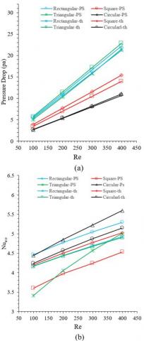
To ensure the accuracy of the results, pure water (∅=0%) pressure drop and heat transfer has been compared with theoretical relations. Straight tube with circular, triangular, square and rectangular sections was considered in this validation. In Figure 5a, theoretical pressure drop (according Eq. 16) is compared with numerical pressure drop. As seen, there is a good agreement between the numerical and theoretical results, and the amount of deviation is between 1% and 12%.
$\Delta p_{t h}=\frac{32 \mu L V}{D_{H}^{2}}$ (17)
In a laminar flow for constant wall temperature, average theoretical Nu obeys the following equation [37]:
$\overline{N U_{D_{H}}}=3.66+\frac{0.0668\left(^{D_{H} / L}\right) \operatorname{Re}_{D_{H} P r}}{1+0.04\left[\left(^{D_{H} / L}\right) \operatorname{Re}_{D_{H} P r}\right]^{\frac{2}{3}}}$ (18)
where, $\mathrm{D}_{\mathrm{H}}$ is hydraulic diameter and can be calculated as below:
$D_{H}=\frac{4 A}{P}$ (19)
Numerical average Nu is expressed as bellow:
$\overline{N u}=\frac{\bar{h} D_{H}}{k}$ (20)
And
$\bar{h}=\frac{-\dot{m} c_{p} L n\left[\frac{T_{o}-T_{W}}{T_{i n}-T_{W}}\right]}{P L}$ (21)
where, $\dot{\mathrm{m}}$ indicates mass flow rate and P represents periphery of tube section. $\mathrm{T}_{\mathrm{in}}, \mathrm{T}_{\mathrm{o}}$ and $\mathrm{T}_{\mathrm{W}}$ are inlet temperature, outlet temperature and wall temperature, respectively. In this study, temperatures are calculated based on $\mathrm{T}_{\mathrm{mean}}$ which is mean temperature of mixture.
$T_{m e a n}=\frac{1}{V A_{c}} \int_{A_{C}} T u d A_{c}$ (22)
where, $A_c$ gives the area of tube cross-section, V is mean velocity and both are defined as bellow:
$V=\frac{1}{A_{C}} \int_{A_{C}} u d A_{C}$ (23)
Figure 4. Numerical and theoretical comparison of pure water (∅=0%) (a) pressure drop (b) average Nu number
In Figure 4b, changes of theoretical and numerical average Nu are presented based on Nu and compared with each other. According to the results, satisfying conformity is observed between numerical and theoretical data so that minimum and maximum deviation is about 2% and 14%, respectively.
Heat transfer performance and pressure drop for helical, spiral and straight tubes has been investigated in this paper. Generally, incompressible laminar flow numerically simulated for nanofluid of water- Al2O3 with 0%, 1%, 3%, 5% and 7% volume fractions. Also, aforementioned states were considered at different Re as well as circular, triangular, square and rectangular sections. Noting that several states are considered, performance of helical, spiral and straight tubes can be compared with each other at a specific cross-section. Or, heat transfer performance of different cross-sections of a determined geometry (like helical) can be compared with each other. In general, this study enables us to determine the most optimal mode among all geometries with different sections. Indeed, at the optimum condition heat transfer performance is high and pressure drop is low.
Assessments show the importance of centrifugal force which increases pressure gradient at the cross-sectional part of curved tubes. Due to velocity gradient between inner and outer wall, the phenomenon of secondary flow is created to balance momentum transfer near the wall and to compensate centrifugal force caused by the curvature.
Temperature distribution for different section types of helical tube is shown in Figure 5, at section with a distance of 12 cm from the entrance (where ∅=0%). As previously noted, secondary flow (at different types of sections) effects on temperature distribution asymmetry that is clearly illustrated in Figure 5.
Velocity profile has been shown for helical tubes with pure water in Figure 6. Flow in curved tubes is under effect of centrifugal force, pressure and viscosity. Pressure gradient caused by tube curvature, creates secondary flow perpendicular to the main flow. Direction of centrifugal force is toward outer wall of curvature, while the direction of pressure force is toward inner wall of curvature. Hence these two forces balance each other. Centrifugal force is proportionate to the square of velocity, therefore according to no slip boundary condition at walls, intensity of centrifugal force is decreased near the walls. Due to the curvature of tube and creation of secondary flow, velocity distribution is not symmetric at cross-sections and its intensity at outer wall is greater than inner wall. With increasing radios of curvature, magnitude of centrifugal force is decreased and accordingly pressure force is increased. Thereupon, at near of walls pressure gradient dominates on the flow and boundary layer formation is from outer side of curvature towards inner side. Whereas, at the central section of tube this phenomenon is vice versa and centrifugal force is dominant factor and its direction is from inner side of curvature towards outer side. Two pairs of vortices are formed due to the interaction of two currents in opposite directions. The lager pair is formed near outer wall and smaller pair near the inner wall. Moreover, centrifugal force pushes maximum axial velocity towards outer wall. Further information about the effect of various parameters of helical tubes on fluid flow can be obtained at [38].
Figure 5. Temperature distribution of different sections (a) straight geometry (b) spiral geometry (c) helical geometry
Figure 6. Velocity distribution at different cross-sections (a) straight geometry (b) spiral geometry (c) helical geometry
4.1 Temperature distribution analyses at different geometries, sections and volume fractions and results comparisons
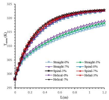
Figure 7 shows temperature distribution at helical, spiral and straight tube with circular cross-section for different volume fractions (Re=200).
Figure 7. The average temperature distribution based on length for helical, spiral and straight geometries with different volume fractions
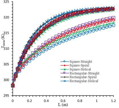
Figure 8. Nanofluid temperature distribution considering spiral, helical and straight tubes with different types of section (Re=200, VF=3%)
As can be seen, the effects of nanofluids high coefficient of heat conduction are obvious. So that, reaching length of fluid temperature to the wall temperature is decreased, with adding nanoparticles into the water. Indeed, volume fraction of 7% has minimum length that temperature of fluid approaches wall temperature in all of spiral, helical and straight tubes. According to Figure 7, at the end of the tube closest fluid temperature to the wall temperature is in the helical geometry. Therefore, helical geometry has better heat transfer performance compared to spiral geometry. Also, spiral geometry has better heat transfer compared to straight geometry. The reason of this phenomenon is the existence of secondary flow in the spiral-shaped geometries. Nanofluid temperature distribution is seen in Figure 8 based on following considerations: Volume fraction of 3%, Re=200 and also straight, helical and spiral geometries whit different cross-sections are considered parameters.
As the results shows, for all three geometries, tube with rectangular and square cross-section has the best and the worst performance, respectively. Accordingly, rectangular cross section has higher temperature than other types of sections at the end of pipe.
4.2 Study of pressure drop, heat transfer rate and FOM at different Reynolds numbers
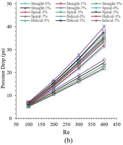
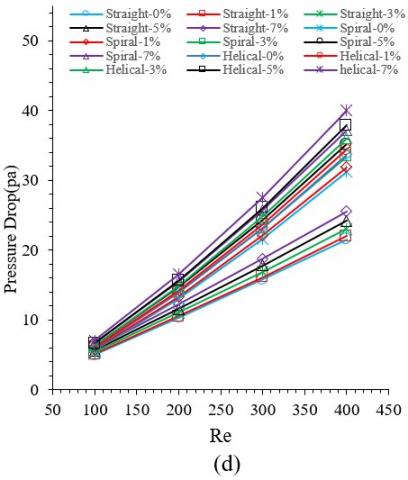
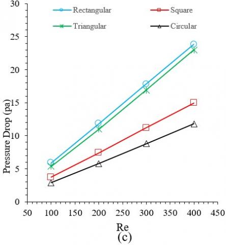
Changes in pressure drop of each section are shown in Figure 9, for different Re. Based on the results, adding nanoparticles into the base fluid increase fluid viscosity and subsequently increases pressure drop in all cases [39]. As regards, with increasing nanofluid volume fraction its viscosity is increased. So obtained results confirm that, nanofluid with 7% volume fraction has maximum amount of pressure drop. So that, in the straight tube with circular cross-section, pressure drop of nanofluid with 7% volume fraction is about 15% more than pure water. Also, it can be observed that, spiral-shaped tubes make greater pressure drop than straight tubes, at constant volume fraction [14]. In spiral-shaped tubes centrifugal force needs excessive energy to conquest wall friction and to create secondary flow. So, more pumping power is required. The maximum and the minimum pressure drop along the tube are related to the helical and straight geometry respectively. As it is clear, pressure drop is increased with increment of Re. Changes of pressure drop by taking specified geometry with various sections for different Re have been illustrated in Figure 10. In all of spiral, helical and straight tubes, tube with rectangular and circular section has the highest and the lowest pressure drop along the tube, respectively. Straight tube with rectangular section makes pressure drop about 51% more than circular section (at Re=200). Also, increment of Re increases pressure drop, so that at Re=400 pressure drop is 75% more than Re=100 in a straight tube with circular section.
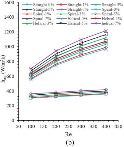
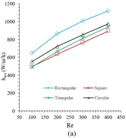
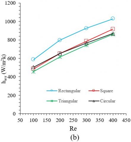
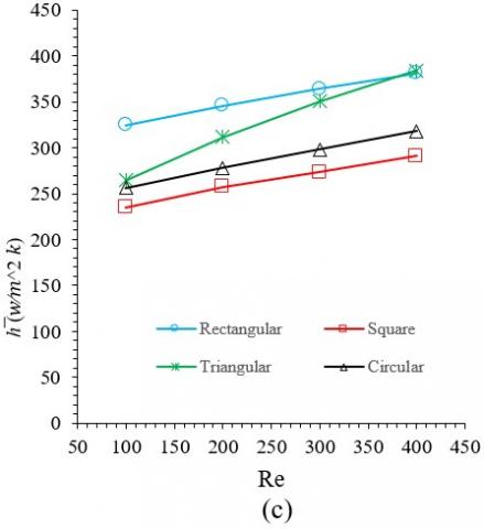
Changes of average heat transfer coefficient in tube with different sections and different Re have been shown in Figure 11. Relative motions of nanoparticles near the wall, increases the rate of heat transfer from the wall to the fluid [40]. This means, as the results demonstrate increment of volume fraction enhances heat transfer coefficient and subsequently heat transfer rate is increased. For instance, in straight tube with circular section, average heat transfer coefficient of pure water (VF=0) at Re=200 is 14% less than fluid with volume fraction of 7%. Because of high thermal conductivity of nanoparticles which augments fluid thermal conductivity [19]. Also, it is worth mentioning, helical tube in all sections has higher average heat transfer coefficient than spiral and straight tubes. The average heat transfer coefficient in circular helical tube is 60% higher than circular straight tube when Re= 200 and VF=3%. This means, curvature in tubes play significant role in heat transfer rate of tubes. The average heat transfer coefficients of helical and spiral tubes with square section are close. For example, the average heat transfer coefficient of spiral tube at Re=400 is 1% higher than helical tube.
Figure 9. Pressure drop changes in tube with Re number for different cross section (a) circular (b) rectangular (c) square (d) triangular
Figure 10. Pressure drop changes in tube with Re number for different geometry (a) helical (b) spiral (c) straight
Figure 11. Changes of average heat transfer coefficient in tube with Re for different cross section (a) circular (b) rectangular (c) square (d) triangular
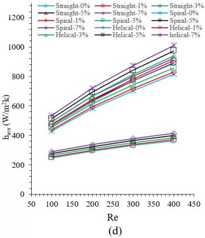
Figure 12. Changes of average heat transfer coefficient in tube with Re for geometry (a) helical (b) spiral (c) straight
Changes of average heat transfer coefficient based on different Re have been shown in Figure 12 for helical, straight and spiral tubes. According to the obtained results, among all geometries and sections tube with rectangular section has higher average heat transfer coefficient and, of course higher heat transfer rate. For instance, average heat transfer coefficient of rectangular straight tube is 25% greater than straight tube with square section if Re=200 and VF=3%. Also, among different geometries and for different Re, tube with square section has lower average heat transfer coefficient. Thermal boundary layer thickness and thermal resistance is diminished with increasing of Re [41]. Thus, the amount of average heat transfer coefficient is increased. For better understanding, average heat transfer coefficient of circular straight tube in Re=400 is 19% more than when Re=100.
In order to evaluate the effect of heat transfer rate and pressure drop simultaneously, FOM parameter has been investigated for each sections of all geometries according to the study of Sasmito [14]. Where, related values have been provided in Table 4. According to the results, the value of FOM in straight tube is greater than spiral and helical tubes. Which means, straight tubes create lower pressure drop than the spiral-shaped tubes (curved tubes). In simple terms, here is a competition between the amount of augmented heat transfer and the amount of pressure drop. Although spiral and helical tubes have higher heat transfer rate than straight tubes, they have higher pressure drop too. So, in curved tubes, more pumping power is required. Among all types of sections, although triangular and rectangular tubes have higher heat transfer rate, but they lead to lower values of FOM due to high pressure drop. Circular and square are such sections which have maximum FOM.
Table 4. The evaluation of FOM in helical, spiral and straight tubes with different sections (VF=3%)
|
Re=200 |
Section |
Pressure Drop (Pa) |
Total Heat Transfer (J/s) |
Figure Of Merit |
|
Straight |
Circular |
5.78 |
146.33 |
25.31 |
|
Rectangular |
11.84 |
198.10 |
16.73 |
|
|
Square |
7.43 |
159.81 |
21.52 |
|
|
Triangular |
11.01 |
199.89 |
18.16 |
|
|
Spiral |
Circular |
7.95 |
178.54 |
22.45 |
|
Rectangular |
14.65 |
226.53 |
15.47 |
|
|
Square |
10.15 |
200.69 |
19.77 |
|
|
Triangular |
13.94 |
229.27 |
16.45 |
|
|
Helical |
Circular |
8.55 |
180.01 |
21.07 |
|
Rectangular |
15.77 |
227.24 |
14.41 |
|
|
Square |
10.79 |
200.50 |
18.57 |
|
|
Triangular |
14.84 |
230.76 |
15.55 |
The main aim of this study is numerical investigation on the heat transfer of the incompressible laminar flow with applying nanoparticles in tubes with different geometries. Different volume fractions of water- Al2O3 nanofluid was passed through spiral, helical and straight tube with circular, triangular, square and rectangular sections at different Re. with adding nanoparticles into water, reaching length of fluid temperature to the wall temperature is reduced and in VF=7% this length is minimum. Adding nanoparticles into base fluid increases pressure drop in all of geometries and sections. Also, at constant volume fraction, helical geometry has maximum pressure drop while straight tube makes minimum pressure drop. With increasing Re, pressure drop is ascended in all cases. In the all of helical, spiral and straight geometries, rectangular tube and circular tube has maximum and minimum pressure drop respectively.
In all of studied volume fractions and sections, Average heat transfer coefficient of helical tube is greater than straight and spiral tubes. Also, by considering all of Re and geometries, tube with square cross-section has minimum average heat transfer coefficient. It should be noted that, with increasing Re in all geometries, volume fractions and sections, the value of average heat transfer coefficient is increased.
As a general conclusion, although spiral and helical tubes have reasonable thermal performance, they make lower FOM than straight tubes due to higher pressure drop. Aforesaid phenomenon is valid for tubes with triangular and rectangular tubes.
|
A |
area ($m^2$) |
|
Cp |
heat capacity ($\mathrm{J} k g^{-1} k^{-1}$) |
|
DH |
hydraulic diameter (m) |
|
h |
heat transfer coefficient ($\mathrm{W} m^{-2} k^{-1}$) |
|
k |
thermal conductivity ($\mathrm{W} m^{-1} k^{-1}$) |
|
L |
tube length (m) |
|
$m ̇$ |
mass flow rate $\left(\mathrm{kg} s^{-1}\right)$ |
|
Nu |
Nusselt number |
|
p |
pressure $\left(\mathrm{N} m^{-2}\right)$ |
|
Pr |
Prandtl number |
|
$Q ̇$ |
heat transfer rate |
|
Re |
Reynolds number |
|
T |
temperature (k) |
|
u,v,w |
velocity components along the x, y and z directions, respectively $\left(\mathrm{m} s^{-1}\right)$ |
|
V |
mean velocity $\left(\mathrm{m} s^{-1}\right)$ |
|
x,y |
cartesian coordinates along the surface and normal to it, respectively |
|
Greek letters |
|
|
α |
thermal diffusivity $\left(m^{2} s^{-1}\right)$ |
|
μ |
fluid dynamic viscosity $\left(\mathrm{N} \mathrm{s} m^{-2}\right)$ |
|
ρ |
density |
|
υ |
fluid kinematic viscosity $\left(m^{2} s^{-1}\right)$ |
|
ϕ |
volume fraction |
|
∆p |
pressure drop |
|
Subscripts |
|
|
f |
fluid |
|
nf |
nanofluid |
|
in |
inlet |
|
out |
outlet |
|
p |
nanoparticles |
|
th |
theory |
|
w ∞ |
condition at the surface ambient condition |
[1] Naphon, P., Wongwises, S. (2006). A review of flow and heat transfer characteristics in curved tubes. Renewable and Sustainable Energy Reviews, 10(5): 463-490. https://doi.org/10.1016/j.rser.2004.09.014
[2] Santini, L., Cioncolini, A., Butel, M.T., Ricotti, M.E., (2016). Flow boiling heat transfer in a helically coiled steam generator for nuclear power applications. International Journal of Heat and Mass Transfer, 92: 91-99. https://doi.org/10.1016/j.ijheatmasstransfer.2015.08.012
[3] Dean, W.R. (1927). XVI. Note on the motion of fluid in a curved pipe. The London, Edinburgh, and Dublin Philosophical Magazine and Journal of Science, 4(20): 208-223. https://doi.org/10.1080/14786440708564324
[4] Dean, W.R. (1928). LXXII. The stream-line motion of fluid in a curved pipe (Second paper). The London, Edinburgh, and Dublin Philosophical Magazine and Journal of Science, 5(30): 673-695. https://doi.org/10.1080/14786440408564513
[5] Kurnia, J.C., Sasmito, A.P., Shamim, T., Mujumdar, A.S. (2016). Numerical investigation of heat transfer and entropy generation of laminar flow in helical tubes with various cross sections. Applied Thermal Engineering, 102: 849-860. https://doi.org/10.1016/j.applthermaleng.2016.04.037
[6] Ardekani, A.M., Kalantar, V., Heyhat, M.M. (2019). Experimental study on the flow and heat transfer characteristics of Ag/water and SiO2/water nanofluids flows in helically coiled tubes. Journal of Thermal Analysis and Calorimetry, 137(3): 779-790. https://doi.org/10.1007/s10973-018-08001-x
[7] Ardekani, A.M., Kalantar, V., Heyhat, M.M. (2019). Experimental study on heat transfer enhancement of nanofluid flow through helical tubes. Advanced Powder Technology, 30(9): 1815-1822. https://doi.org/10.1016/j.apt.2019.05.026
[8] Ciofalo, M., Arini, A., Di Liberto, M. (2015). On the influence of gravitational and centrifugal buoyancy on laminar flow and heat transfer in curved pipes and coils. International Journal of Heat and Mass Transfer, 82: 123-134. https://doi.org/10.1016/j.ijheatmasstransfer.2014.10.074
[9] Nobari, M., Amani, E. (2009). A numerical investigation of developing flow and heat transfer in a curved pipe. International Journal of Numerical Methods for Heat & Fluid Flow, 19(7): 847-873. https://doi.org/10.1108/09615530910984118
[10] Pan, C.Z., Zhang, T., Wang, J.J., Zhou, Y. (2018). CFD study of heat transfer and pressure drop for oscillating flow in helical rectangular channel heat exchanger. 129: 106-114. https://doi.org/10.1016/j.ijthermalsci.2018.02.035
[11] Hardik, B.K., Baburajan, P.K., Prabhu, S.V. (2015). Local heat transfer coefficient in helical coils with single phase flow. International Journal of Heat and Mass Transfer, 89: 522-538. https://doi.org/10.1016/j.ijheatmasstransfer.2015.05.069
[12] Kim, Y.I., Kim, S.H., Hwang, Y.D., Park, J.H. (2011). Numerical investigation on the similarity of developing laminar flows in helical pipes. Nuclear Engineering and Design, 241(12): 5211-5224. https://doi.org/10.1016/j.nucengdes.2011.09.020
[13] Naphon, P., Suwagrai, J. (2007). Effect of curvature ratios on the heat transfer and flow developments in the horizontal spirally coiled tubes. International Journal of Heat and Mass Transfer, 50(3-4): 444-451. https://doi.org/10.1016/j.ijheatmasstransfer.2006.08.002
[14] Sasmito, A.P., Kurnia, J.C., Wang, W., Jangam, S.V. Mujumdar, A.S. (2012). Numerical analysis of laminar heat transfer performance of in-plane spiral ducts with various cross-sections at fixed cross-section area. International Journal of Heat and Mass Transfer, 55(21): 5882-5890. https://doi.org/10.1016/j.ijheatmasstransfer.2012.05.085
[15] Kurnia, J.C., Sasmito, A.P., Mujumdar, A.S. (2014). Laminar heat transfer performance of power law fluids in coiled square tube with various configurations. International Communications in Heat and Mass Transfer, 57: 100-108. https://doi.org/10.1016/j.icheatmasstransfer.2014.07.016
[16] Kurnia, J.C., Sasmito, A.P., Jangam, S.V., Mujumdar, A.S. (2013). Heat transfer in coiled square tubes for laminar flow of slurry of microencapsulated phase change material. Heat Transfer Engineering, 34(11-12): 994-1007. https://doi.org/10.1080/01457632.2012.753821
[17] Kurnia, J.C., Sasmito, A.P., Mujumdar, A.S. (2011). Numerical investigation of laminar heat transfer performance of various cooling channel designs. Applied Thermal Engineering, 31(6-7): 1293-1304. https://doi.org/10.1016/j.applthermaleng.2010.12.036
[18] Sasmito, A.P., Kurnia, J.C., Mujumdar, A.S. (2011). Numerical evaluation of laminar heat transfer enhancement in nanofluid flow in coiled square tubes. Nanoscale Research Letters, 6(1): 376. https://doi.org/10.1186/1556-276X-6-376
[19] Kakaç, S., Pramuanjaroenkij, A. (2009). Review of convective heat transfer enhancement with nanofluids. International Journal of Heat and Mass Transfer, 52(13-14): 3187-3196. https://doi.org/10.1016/j.ijheatmasstransfer.2009.02.006
[20] Das, S.K., Choi, S.U., Yu, W., Pradeep, T. (2007). Nanofluids: Science and Technology. John Wiley & Sons.
[21] Xuan, Y., Roetzel, W. (2000). Conceptions for heat transfer correlation of nanofluids. International Journal of Heat and Mass Transfer, 43(19): 3701-3707. https://doi.org/10.1016/S0017-9310(99)00369-5
[22] Rahman, M.R.A., Leong, K.Y., Idris, A.C., Saad, M.R., Anwar, M. (2017). Numerical analysis of the forced convective heat transfer on Al2O3–Cu/water hybrid nanofluid. Heat and Mass Transfer, 53(5): 1835-1842. https://doi.org/10.1007/s00231-016-1941-z
[23] Xuan, Y., Li, Q. (2000). Heat transfer enhancement of nanofluids," International Journal of Heat and Fluid Flow, 21(1): 58-64. https://doi.org/10.1016/S0142-727X(99)00067-3
[24] Rahman, M.R.A., Leong, K.Y., Idris, A.C., Saad, M.R.J. (2017). Thermal fluid dynamics of Al2O3–Cu/Water hybrid nanofluid in inclined lid driven cavity. 6(1): 149-154. https://doi.org/10.1166/jon.2017.1300
[25] Maiga, S.E.B., Palm, S.J., Nguyen, C.T., Roy, G., Galanis, N. (2005). Heat transfer enhancement by using nanofluids in forced convection flows. International Journal of Heat and Fluid Flow, 26(4): 530-546. https://doi.org/10.1016/j.ijheatfluidflow.2005.02.004
[26] Sheikholeslami, M., Sajjadi, H., Delouei, A.A., Atashafrooz, M., Li, Z. (2019). Magnetic force and radiation influences on nanofluid transportation through a permeable media considering Al2O3 nanoparticles. Journal of Thermal Analysis and Calorimetry, 136(6): 2477-2485. https://doi.org/10.1007/s10973-018-7901-8
[27] Huminic, G., Huminic, A. (2011). Heat transfer characteristics in double tube helical heat exchangers using nanofluids. International Journal of Heat and Mass Transfer, 54(19-20): 4280-4287. https://doi.org/10.1016/j.ijheatmasstransfer.2011.05.017
[28] Atashafrooz, M. (2018). Effects of Ag-water nanofluid on hydrodynamics and thermal behaviors of three-dimensional separated step flow. Alexandria Engineering Journal, 57(4): 4277-4285. https://doi.org/10.1016/j.aej.2017.07.016
[29] Mirfendereski, S., Abbassi, A., Saffar-avval, M. (2015). Experimental and numerical investigation of nanofluid heat transfer in helically coiled tubes at constant wall heat flux. Advanced Powder Technology, 26(5): 1483-1494. https://doi.org/10.1016/j.apt.2015.08.006
[30] Akbaridoust, F., Rakhsha, M., Abbassi, A., Saffar-Avval, M. (2013). Experimental and numerical investigation of nanofluid heat transfer in helically coiled tubes at constant wall temperature using dispersion model. International Journal of Heat and Mass Transfer, 58(1-2): 480-491. https://doi.org/10.1016/j.ijheatmasstransfer.2012.11.064
[31] Naphon, P. (2016). Experimental investigation the nanofluids heat transfer characteristics in horizontal spirally coiled tubes. International Journal of Heat and Mass Transfer, 93: 293-300. https://doi.org/10.1016/j.ijheatmasstransfer.2015.09.089
[32] Nassan, T.H., Heris, S.Z., Noie, S.H. (2010). A comparison of experimental heat transfer characteristics for Al2O3/water and CuO/water nanofluids in square cross-section duct. International Communications in Heat and Mass Transfer, 37(7): 924-928. https://doi.org/10.1016/j.icheatmasstransfer.2010.04.009
[33] Hassani, M., Lavasani, M.A., Kim, Y.S., Ghergherehchi, M. (2019). Numerical investigation of nanofluid Al2O3/Water in elliptical tube equipped with twisted tape. International Journal of Heat and Technology, 37(2): 520-526. https://doi.org/10.18280/ijht.370219
[34] Heris, S.Z., Nassan, T.H., Noie, S.H., Sardarabadi, H., Sardarabadi, M. (2013). Laminar convective heat transfer of Al2O3/water nanofluid through square cross-sectional duct. International Journal of Heat and Fluid Flow, 44: 375-382. https://doi.org/10.1016/j.ijheatfluidflow.2013.07.006
[35] Brinkman, H.C. (1952). The viscosity of concentrated suspensions and solutions. J. Chem. Phys., 20(4): 571-571. https://doi.org/10.1063/1.1700493
[36] Wasp, E.J., Kenny, J.P., Gandhi, R.L. (1977). Solid--liquid flow: slurry pipeline transportation.[Pumps, valves, mechanical equipment, economics]. Ser. Bulk Mater. Handl.; (United States), 1(4).
[37] Incropera, F., DeWitt, D. (1990). Fundamentals of Heat and Mass Transfer. John Wiley and Sons, New York.
[38] Nobari, M., Malvandi, A. (2013). Torsion and curvature effects on fluid flow in a helical annulus. International Journal of Non-Linear Mechanics, 57: 90-101. https://doi.org/10.1016/j.ijnonlinmec.2013.06.014
[39] Narrein, K., Mohammed, H.A. (2013). Influence of nanofluids and rotation on helically coiled tube heat exchanger performance. Thermochimica Acta, 564: 13-23. https://doi.org/10.1016/j.tca.2013.04.004
[40] Kahani, M., Heris, S.Z., Mousavi, S.M. (2013). Comparative study between metal oxide nanopowders on thermal characteristics of nanofluid flow through helical coils. Powder Technology, 246: 82-92. https://doi.org/10.1016/j.powtec.2013.05.010
[41] Yarmand, H., Gharehkhani, S., Shirazi, S.F.S., Amiri, A., Alehashem, M.S., Dahari, M., Kazia, S.N. (2016). Experimental investigation of thermo-physical properties, convective heat transfer and pressure drop of functionalized graphene nanoplatelets aqueous nanofluid in a square heated pipe. Energy Conversion and Management, 114: 38-49. https://doi.org/10.1016/j.enconman.2016.02.008