Ibtissem Sifi* | Nassera Ghellai | Abdelkader Hima | Younes Menni | Ali J. Chamkha | Giulio Lorenzini
© 2019 IIETA. This article is published by IIETA and is licensed under the CC BY 4.0 license (http://creativecommons.org/licenses/by/4.0/).
OPEN ACCESS
Thermoelectric-power generation poses challenges, which are of fundamental and technological nature. Increasing thermoelectric efficiency for work, the therme of the associated policy, has encountered problems related, for example, to heat recovery and conversion to electricity. It is widely recognized that the augmentation of efficient electromechanical systems as a strategic subject of applied study in light of problems related, for example, to waste heat recuperation and conversion to electricity. This results in an abundant literature on the subject. Recent advances in the technological development of TEGs are based on advances in materials science: new materials and new techniques for the production of specific structures have made it possible to improve device performance through the characterization and optimization of their thermal and electrical transport properties. This paper presents a simulation study on the effect of temperature variation on a thermoelectric generator at the base of BiCuSeO, using the mathematical method of the finite element model.
semiconductor, energy conversion, temperature, thermoelectric generator, finite element model, BiCuSeO
Energy recovery is a good way to overcome battery limitations. Energy from various sources of ambient forms such as vibration, heat and noise can be transformed to electrical energy through energy recovery. Among these sources of ambient energy, we can note thermal energy which can be converted into electrical energy using a thermoelectric generator. Glatz et al. [1] presented a novel polymer based wafer level fabrication process for micro thermoelectric generators (μTEGs) for the application on non-planar surfaces. In that study, the generators were fabricated by subsequent electrochemical deposition of Cu and Ni in a 190-μm thick flexible polymer mold formed by photolithographic (PL) patterning of SU-8. Their results showed that the thermocouple length should be in the range of 80-150μm when the best thermoelectric bulk material (BiTe) is used and realistic interface condition are assumed. Shittu et al. [2] numerically investigated a segmented asymmetrical thermoelectric generator (SASTEG) to optimize its electrical performance and mechanical reliability under transient and steady state conditions. They studied and compared the thermal and electrical performance of the SASTEG and TEG under transient and steady state heating conditions. Their results showed that the optimized SASTEG provided a power output enhancement of 117.11 % compared to that of the conventional TEG under rectangular pulsed heat condition. Kim et al. [3] reported a glass fabric-based flexible TE generator prepared using a screen printing technique and the self-sustaining structure of a TE device without top and bottom substrates. They showed an allowable bending radius of as low as 20 mm and no change in performance by repeated bending for 120 cycles. Zappa et al. [4] synthesized and preliminarily investigated Zinc oxide (ZnO, n-type) and copper oxide (CuO, p-type) nanowires as innovative materials for the fabrication of a proof-of-concept thermoelectric device. Thacher et al. [5] conducted a study to measure the automobile exhaust thermoelectric generator (AETEG)’s performance and its effect on the truck systems as well as to determine which factors are important for optimizing an AETEG design. Other studies can be found [6-24].
In this work, we present a simulation study on the effect of temperature variation on a thermoelectric generator at the base of BiCuSeO, using the mathematical method of finite element model. We studied thermoelectric effects: Seebeck effect Peltier effect, Thomson and Kelvin relation. The results of the simulation obtained are in good agreement with the experimental and theoretical data available. Matlab has been used in the current calculation.
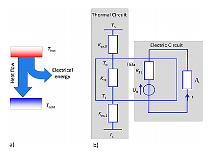
Figure 1a presents the energy fluxes in a thermoelectric device; there is a thermal flux from a thermal source. While a part of this thermal flux is transformed into an electric energy flux within the thermoelectric material. A thermal drain absorbs the remaining thermal energy. In Figure 1b the electrical and thermal part is plotted separately in a composite component model, where the properties of spatially distributed material, such as electrical and thermal conductivity, are expressed by aggregating elements.
Figure 1. (a) the energy fluxes within a thermoelectric conversion process, (b) the thermal and electrical part separately in a lumped element model
2.1 Method of finite volume model of thermoelectric module
Due to the phenomenon of electron and phonon transport in conductors and semiconductors, heat flux and electrical current are, in general, coupled and linear functions of the electric field and the gradient of temperature:
$\mathrm{J}=\sigma \mathrm{E}-\sigma \alpha \mathrm{VT}$ (1)
$\mathrm{q}=\pi \mathrm{J}-\mathrm{K} \nabla \mathrm{T}$ (2)
However, even without knowing exactly what the coefficients α, π, σ, k are, it is clear from Eqs. (1) and (2) that in any material which allows both electrical and heat conduction.
The system for the method of “Finite Volume Model of Thermoelectric Module” consists of three domains with four boundaries. The sub-domains and their equations as represent in Figure 2.
Figure 2. Sub-domain equations
Sub-domains I and III represent sink and the heat source, respectively, and sub-domain II represents the thermoelectric material. Figure 2 represents the time-dependent equations that are obtained by substituting Eqns. (1) and (2) for the conservation of heat flux and the load equations 3 and 4 presented below:
$\nabla \mathrm{J}+\frac{\partial \rho}{\partial \mathrm{t}}=0$ (3)
$\mathrm{q}+\rho \mathrm{C}_{\mathrm{v}} \frac{\mathrm{dT}}{\mathrm{dt}}=\dot{\mathrm{Q}}=\mathrm{EJ}$ (4)
The thermal boundary conditions are:
1.A: Heat flux q0 is imposed:
$-\mathrm{K} \frac{\partial \mathrm{T}}{\partial \mathrm{x}}=\mathrm{q}_{0}$ (5)
2. B: Heat is continuous across the interface flux balance; A current J0 is imposed J = J0.
3. C: Heat is continuous across the interface flux balance; a voltage V0 is imposed V = 0.
4. D: Temperature Tamb is imposed T = Tamb.
It is assumed that k, ρ, Cv, ϵ and σ are constant within each sub-domain; they can and will differ between domains due to material differences. In sub-domain II, α = αT: a function of temperature and k, ρ, Cv are constants.
Figure 3 indicates the temperature dependence of the thermoelectric generator properties for Bi1-xBa-xCuSeO samples.
Figure 3. Thermoelectric properties of Bi1-xBa-xCuSeO as a function of temperature, (a) electrical conductivity, (b) Seebeck coefficient, (c) power factor, (d) total thermal conductivity, (e) Lattice thermal conductivity, (f) Figure of merit ZT
2.2 Boundary conditions for temperature at points B and C: Tb, Tc
The temperature at the B limit is given by the following equation:
$\begin{aligned} T_{B}=&\left(R_{t h} x N_{\max }+R_{\max } x N_{\max }+1+\frac{2 \alpha R_{t h} R_{\max } N_{\max }+1^{2}}{R_{e}}-\right.\\ &\left.\frac{R_{\max } \alpha x N_{\max }+1 x N_{\max }+2 N+N_{\min }+1}{2 R_{e}}\right) \times \frac{1}{R_{t h}+R_{\max } \alpha 2 x \frac{N \max +1}{R_{e}}} \end{aligned}$ (6)
The temperature at the B limit is given by the following equation:
$\begin{aligned} T_{C}=\left(R_{t h} x N_{\max }+N+1+R_{\min } x N_{\max }+N+\right.& \\\left.\frac{\alpha(N)^{2} R_{t h} R_{\max } N_{\max }+N^{2}}{R_{e}}+\alpha R_{t h} R_{\min } x \frac{N_{\max }+N x N_{\max }+2 N+N_{\min }+2}{2 R_{e}}\right) \times \\ \frac{1}{R_{t h}+R_{\min }+\frac{\alpha N^{2} R_{t h} R_{\min } x N_{\max }+N}{R_{e}}} \end{aligned}$ (7)
2.3 Derived functions
The derived functions are connected by the length of the thermoelectric module and the time of the generation of power: [25]
$\dot{Q}(x, t)=\frac{Q_{i n}+\frac{x}{R_{\max }}}{C_{\max }}$ (8)
$d Q(x, t) N_{\max }-1=C_{\max } \frac{x N_{\max }-2 x+x N_{\max }-1+x N_{\max }-2}{R_{\max }}$ (9)
$d Q(x, t) N_{\max }=2 \frac{T_{B}-x N \max }{N_{\max }}-C_{\max } \frac{x N_{\max }-x N_{\max }-1}{N_{\max }}$ (10)
$\begin{aligned} d Q(x, t) N_{\max }+1=& \frac{1}{R_{e}}\left(x N_{\max }+N+N_{\min }+1\right)^{2}-\\ \alpha x\left(N_{\max }+N+N_{\min }+1\right) \frac{x N_{\max }+2+x N_{\max }+1}{2-T_{B}}-\end{aligned}$
$\frac{\alpha x N_{\max }+2+x N_{\max }+1}{2 x\left(N_{\max }+N+N_{\min }+2\right)}+\frac{x\left(N_{\max }+N+N_{\min }+1\right)}{2}-$
$\frac{T_{B} x\left(2 N+N_{\max }+N_{\min }+1\right)}{R_{e}}+\frac{\alpha^{2}}{R_{e}} x N_{\max }+2+x N_{\max }+$
1$\frac{x N_{\max }+2-x N_{\max }+1}{2-2 T_{B}\left(x N_{\max }+1\right)-T_{B}}$
$+\frac{x\left(N_{\max }+2\right)-x\left(N_{\max }+1\right)}{2 \frac{T_{B}-x\left(N_{\max }\right)}{R_{\operatorname{th}} C_{t h}}}$
(11)
$\begin{aligned} d Q(x, t) N_{\max }+N+N_{\min }+1=& I-x \frac{N_{\max }+N+N_{\min }+1}{R_{e}}+\\ & \alpha \frac{\left(x N_{\max }+2\right)+x N_{\max }+1}{2-T_{B}} \frac{R_{e}}{C_{e}} \end{aligned}$ (12)
$\begin{aligned} d Q(x, t) & N_{\max }+N-1=\frac{1}{R_{e}}\left(x\left(N+N_{\min }+1+N_{\max }+\right.\right.\\N-1)^{2}-\frac{1}{2} \alpha & N-1 x N+N_{\min }+N_{\max }+N-\end{aligned}$
$1 x N_{\max }+N-1+1-x N_{\max }+N-1-1-\alpha N-$
$1 \frac{x N \max +N+x N \max +N-1}{2} \times$
$\frac{x N+N \min +N \max +N+x N+N \min ^{2}+N \max +N-1}{2}-$
$\left(\frac{x N_{\max }+N-1+x N_{\max }+N-2}{2}\right)\left(\frac{x N+N \min +N_{\max }+N-1}{2 R_{e}}+\right.$
$\frac{x N+N \min +N \max +N-2}{2 R_{e}}+$
$\alpha \frac{(N-1)^{2}}{R_{e}} \frac{x N_{\max }+N+x N_{\max }+N-1 x N_{\max }+N-x N \max +N-1}{2}-$
$\frac{x N_{\max }+N-1+x N_{\max }+N-2 x N_{\max }+N-1-x N_{\max }+N-2}{2}+$
$C_{t h} \frac{x N_{\max }+N-2 x N_{\max }+N-1+x N_{\max }+N-1+x N_{\max }+N-2}{R_{t h}}$
(13)
$d Q(x, t) N_{\max }+N-1+N+N_{\min }=$
$\frac{I-x N \max +N-1+N+N \min }{R_{e}}+$
$C_{e} \frac{\alpha N-1+N \min ^{x N} \max ^{+} N+N+N \min -x N_{\max }+N-2+N+N \min }{2 R_{e}}$ (14)
$d Q(x, t) N_{\max }+2 N+N_{\min }=I-\frac{x N_{\max }+2 N+N_{\min }}{R_{e}}$
$+\frac{C_{e}}{R_{e}} \alpha(N)$ (15)
$\begin{aligned} d Q(x, t) N_{\max }+N &=\frac{1}{R_{e}}\left(x\left(N_{\max }+2 N+N_{\min }\right)^{2}-\right.\\ \alpha &(N) x N_{\max }+2 N+N_{\min }\left(T_{C}-\right.\end{aligned}$
$\left.\frac{x\left(N_{\max }+N\right)+x\left(N_{\max }+N-1\right)}{2}\right)-\alpha(N)\left(T_{C} x 2 N+N_{\max }+\right.$
$2+N_{\min }-$
$\frac{x\left(N_{\max }+N-1\right)+x\left(N_{\max }+N\right)}{2} \frac{x\left(N_{\max }+2 N+N_{\min }\right)+x\left(N_{\max }+2 N+N_{\min }-1\right)}{2 R_{e}}+$
$\frac{(\alpha(N))^{2}}{R_{e}}\left(T_{C}-x\left(N_{\max }+N\right)\right)-\left(x\left(N_{\max }+N\right)+\right.$
$\left.x\left(N_{\max }+N-1\right)\left(\frac{x\left(N_{\max }+N\right)-x\left(N_{\max }+N-1\right)}{2}\right)\right)+$
$\frac{x\left(N_{\max }+N-1\right)-x\left(N_{\max }+N\right)}{R_{t h}}+2 \frac{T_{C}-x\left(N_{\max }+N\right)}{C_{t h} R_{t h}}$ (16)
$\begin{aligned} d Q(x, t) N_{\max }+N+1=& \frac{1}{C_{\min }}\left(-2 \frac{x\left(N_{\max }+N-1\right)-T_{C}}{R_{\min }}+\right.\\ &\left.\frac{x\left(N_{\max }+N+2\right)-x\left(N_{\max }+N+1\right)}{R_{\min }}\right) \end{aligned}$ (17)
$d Q(x, t) N_{\max }+N+N_{\min }-1=$
$\frac{x N \max +N+N_{\min }-2 x N_{\max }+N+N_{\min }-2}{C_{\min } R_{\min }}$ (18)
$d Q(x, t) N_{\max }+N+N_{\min }=$
$\frac{x N_{\max }+N+N_{\min }-1-x N_{\max }+N+N_{\min }}{R_{\min }}+2 \frac{T_{a}-x N_{\max }+N+N_{\min }}{R_{\min } C_{\min }}$ (19)
$d Q(x, t) 2 N+N_{\max }+N+N_{\min }+1=$
$\frac{I-\frac{2 x 2 N+N m a x+N+N}{R_{\Theta}} \min ^{+1}+\frac{2 \alpha x N m a x+1-T_{B}}{R_{\Theta}}}{C_{e}}$ (20)
$d Q(x, t) 2 N+N_{\max }+N+N_{\min }+2=$
$\frac{I-\frac{2 x 2 N+N \max +N+N_{\min }+2}{R_{\Theta}}+\frac{2 \alpha T_{C}-x N \max +N}{R_{e}}}{C_{e}}$ (21)
The initial conditions for the temperature are:
$T_{\text {initiale}}=T_{\text {ambiante}}$
The initial conditions for the voltage are:
$V_{i}=0 V$
$V_{g}=\sum V x 2 N+N_{\max }+N_{\min }$ (22)
The current generated I by this thermoelectric generator is given by the following equation:
$\mathrm{P}=\mathrm{R} \mathrm{I}^{2} \rightarrow \mathrm{I}^{2}=\frac{\mathrm{P}}{\mathrm{R}} \rightarrow \mathrm{I}=\sqrt{\frac{\mathrm{P}}{\mathrm{R}}}$ (23)
The merit factor is:
$\mathrm{ZT}=\mathrm{TS}^{2} \frac{\sigma}{\lambda}$ (24)
The efficiency of a thermoelectric generator depends on the merit factor of the material [26]:
$\eta \%=\frac{\mathrm{p}}{\mathrm{Qc}}=\frac{\mathrm{T}_{\mathrm{c}}-\mathrm{T}_{\mathrm{f}}}{\mathrm{T}_{\mathrm{c}}} \times \frac{\sqrt{(1+\mathrm{ZT})}-1}{\sqrt{(1+\mathrm{ZT})}+\frac{\mathrm{T}}{\mathrm{T}_{\mathrm{c}}}} \times 100$ (25)
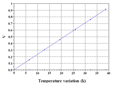
3.1 Seebeck effect V=f (ΔT) depending voltage with the temperature
The curve shows that the voltage is temperature dependent, so this characteristic in Figure 4 shows that the Seebeck coefficient is sensitive to the temperature T.
The Seebeck effect is the transformation of the temperature gradient between the junctions of different metals into an electrical voltage in the milli-volt range of a difference in temperature. Effect is nonlinear with the temperature is depends on the construction of the materials. The Seebeck coefficient S is the amount of voltage difference ∆V generated for an applied temperature difference ∆T.
$\mathrm{S}=\frac{\Delta \mathrm{V}}{\Delta \mathrm{T}}$ (26)
The voltage difference is calculate using the following equation [27]
$\mathrm{V}=\int_{\mathrm{T}_{\mathrm{c}}}^{\mathrm{T}_{\mathrm{h}}}\left(\mathrm{S}_{\mathrm{B}}(\mathrm{T})-\mathrm{S}_{\mathrm{A}}(\mathrm{T})\right) \mathrm{d} \mathrm{T}$ (27)
Figure 4. Depending voltage with the temperature
3.2 Peltier effect
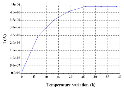
3.2.1 I=f (ΔT), depending electric current with the temperature
Figure 5 shows that the Peltier effect is that a current cause a temperature difference between the junctions of two different metals.
The heat transfer is in the direction of charge carriers.The following equation represents the thermal current density, where j and ᴨ are the electrical current density and the Peltier coefficient [28].
$\mathrm{q}=\mathrm{II}j $ (28)
The thermoelectricity is a nonlinear effect in temperature and voltage, at low currents and temperature differences the nonlinearity is small, and the rough location of the peak, equation 9 represent the power in terms of current:
$\mathrm{I}_{P_{\max }} \approx \frac{\alpha \Delta \mathrm{T}}{2 R_{t e}}$ (29)
where, Rte is the electrical resistance of the thermoelectric module [29].
Figure 5. Depending electric current with the temperature
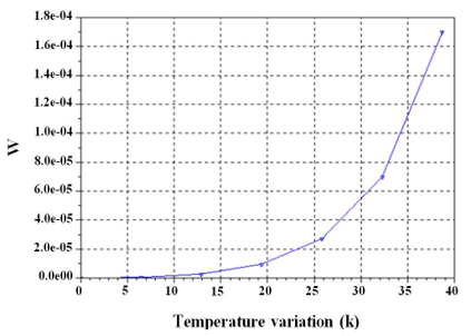
3.2.2 W=f (ΔT), depending power generated with the temperature
The power generated show in Figure 6, for heat is distributed equally to both ends of the leg requires a high thermal conductivity.
Figure 6. Depending power generated with the temperature
The thermal conductivity follows the Fourier process with its heat transfer, Qtc described by:
$\mathrm{Q}_{\mathrm{tc}}=-\Delta \mathrm{T} \mathrm{K}_{\mathrm{tc}}$ (30)
where, DT is the difference between the hot side and cold side temperature and K is the thermal conductivity, when the electric current flows the Joule effect is generated internally. This effect is on both hot side and cold side with amount of energy as:
Q_{\textrm{joule} } $=\mathrm{I}^{2}$ (31)
where, R is the electrical resistance. The Peltier effect is the heating effect when the electric current passes two dissimilar junctions and the total heat transfer is represented by:
$\mathrm{Q}_{\text {Pelier }}=\alpha \Delta \mathrm{T} \mathrm{I}$ (32)
where, α is the Seebeck coefficient. The Seebeck effect is a phenomenon in that a difference in temperature between two dissimilar semiconductors produces a difference in voltage between its two junctions. Seebeck coefficient is also defined as [30].
$\alpha=\frac{\mathrm{V}}{\Lambda \mathrm{T}}$ (33)
3.3 Thomson and Kelvin relation
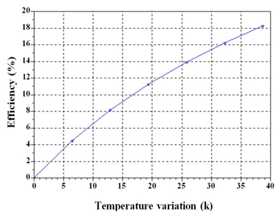
3.3.1 η=f (ΔT), depending efficiency with the temperature shown in Figure 7, the maximum efficiency is equal 18.1 %. The Thomson Effect is the heat flow across a conductor, with terminals at different temperatures, due to current flow.
Figure 7. Depending efficiency with the temperature
The heat flow is given by:
$\frac{\mathrm{d} \mathrm{Q}}{\mathrm{dx}}=\mu \mathrm{I} \frac{\mathrm{dT}}{\mathrm{dx}}$ (34)
For a given material the Thomson effect is the only measurable effect because the other effects are related to pairs of materials. The following equations represent the Thomson/Kelvin relationship for three thermoelectric effects.
$\pi=\mathrm{ST}$ (35)
$\mu=\mathrm{T} \frac{\mathrm{d} S}{\mathrm{d} \mathrm{T}}$ (36)
S, ᴨ, µ, T are the Seebeck coefficient, the Peltier coefficient, the Thomson coefficient, and the absolute temperature.
The efficiency of a thermoelectric generator depends on the merit factor of the material.
3.3.2 ZT=f (ΔT), depending figure of merit with the temperature.
TEGs consist of a cold junction and a hot junction and use the temperature variation between each junction to generate electrical current. Figure 8 shows that the maximum merit value is 1.1.
The properties of the materials and the structure of the device are factors which define the efficiency of the energy conversion. A good thermoelectric material must be possessed of a low thermal conductivity, a high Seebeck coefficient and a high electrical conductivity [31].
The suitability of a thermoelectric material is usually evaluated by the dimensionless thermoelectric figure-of-merit.
Figure 8. Depending figure of merit with the temperature
The new properties of those material structures of the materials are factors that exhibit the energy conversion efficiency of the TEGs. To ameliorate its efficiency, the material needs a high electrical conduction and a good Seebeck coefficient and low thermal conductivity.
The results obtained show the Seebeck coefficient is sensitive to the temperature; he depends on the construction of the materials. The Peltier effect causes a temperature difference between the junctions of two different metals.
Electricity materials could be a parameter that shows that the energy potential conversion is restricted. According to the energy conversion potency is limited.
On the other hand, the efficiency of a thermoelectric generator depends on the merit factor of the material Based on these results, to have a good thermoelectric material it is necessary to have a low thermal conductivity, a high Seebeck coefficient and a high electrical conductivity.
[1] Glatz, W., Muntwyler, S., Hierold, C. (2006). Optimization and fabrication of thick flexible polymer based micro thermoelectric generator. Sensors and Actuators A, 132: 337-345. https://doi.org/10.1016/j.sna.2006.04.024
[2] Shittu, S., Li, G., Zhao, X., Ma, X., Akhlaghi, Y.G., Ayodele, E. (2019). Optimized high performance thermoelectric generator with combined segmented and asymmetrical legs under pulsed heat input power. Journal of Power Sources, 428: 53-66. https://doi.org/10.1016/j.jpowsour.2019.04.099
[3] Kim, S.J., We, J.H., Cho, B.J. (2014). A wearable thermoelectric generator fabricated on a glass fabric. Energy Environ. Sci., 7: 1959-1965. https://doi.org/10.1039/c4ee00242c
[4] Zappa, D., Dalola, S., Faglia, G., Comini, E., Ferroni, M., Soldano, C., Ferrari, V., Sberveglieri, G. (2014). Integration of ZnO and CuO nanowires into a thermoelectric module. Beilstein Journal Nanotechnol, 5: 927-936. https://doi.org/10.3762/bjnano.5.106
[5] Thacher, E.F., Helenbrook, B.T., Karri, M.A., Richter, C.J. (2007). Testing of an automobile exhaust thermoelectric generator in a light truck. Proceedings of the Institution of Mechanical Engineers, Part D: Journal of Automobile Engineering, 221: 95-107. https://doi.org/10.1243/09544070JAUTO51
[6] Ming, T., Yang, W., Wu, Y., Xiang, Y., Huang, X., Cheng, J., Li, X., Zhao, J. (2017). Numerical analysis on the thermal behavior of a segmented thermoelectric generator. International Journal of Hydrogen Energy, 42(5): 3521-3535. https://doi.org/10.1016/j.ijhydene.2016.11.021
[7] Ouyang, Z., Li, D. (2018). Design of segmented high-performance thermoelectric generators with cost in consideration. Applied Energy, 221: 112-121. https://doi.org/10.1016/j.apenergy.2018.03.106
[8] Ge, Y., Liu, Z., Sun, H., Liu, W. (2018). Optimal design of a segmented thermoelectric generator based on three-dimensional numerical simulation and multi-objective genetic algorithm. Energy, 147: 1060-1069. https://doi.org/10.1016/j.energy.2018.01.099
[9] Shittu, S., Li, G., Zhao, X., Ma, X. (2019). Series of detail comparison and optimization of thermoelectric element geometry considering the PV effect. Renewable Energy, 130: 930-942. https://doi.org/10.1016/j.renene.2018.07.002
[10] Li, G., Shittu, S., Ma, X., Zhao, X. (2019). Comparative analysis of thermoelectric elements optimum geometry between Photovoltaic-thermoelectric and solar thermoelectric. Energy, 171: 599-610. https://doi.org/10.1016/j.energy.2019.01.057
[11] Elsheikh, M.H., Shnawah, D.A., Sabri, M.F.M., Said, S.B.M., Hassan, H.M., Bashir, A.M.B., Mohamad, M. (2014). A review on thermoelectric renewable energy: Principle parameters that affect their performance. Renewable and Sustainable Energy Reviews, 30: 337-355. https://doi.org/10.1016/j.rser.2013.10.027
[12] He, W., Zhang, G., Zhang, X., Ji, J., Li, G., Zhao, X. (2015). Recent development and application of thermoelectric generator and cooler. Applied Energy, 143: 1-25. https://doi.org/10.1016/j.apenergy.2014.12.075
[13] Sornek, K., Filipowicz, M., Zołądek, M., Kot, R., Mikrut, M. (2019). Comparative analysis of selected thermoelectric generators operating with wood-fired stove. Energy, 166: 1303-1313. https://doi.org/10.1016/j.energy.2018.10.140
[14] Champier, D. (2017). Thermoelectric generators: A review of applications. Energy Conversion and Management, 140: 167-181. https://doi.org/10.1016/j.enconman.2017.02.070
[15] Fernandez-Yanez, P., Armas, O., Capetillo, A., Martínez-Martínez, S. (2018). Thermal analysis of a thermoelectric generator for light-duty diesel engines. Applied Energy, 226: 690-702. https://doi.org/10.1016/j.apenergy.2018.05.114
[16] Kempf, N., Zhang, Y. (2016). Design and optimization of automotive thermoelectric generators for maximum fuel efficiency improvement. Energy Conversion and Management, 121: 224-231. https://doi.org/10.1016/j.enconman.2016.05.035
[17] Suarez, F., Nozariasbmarz, A., Vashaee, D., Oztürk, M.C. (2016). Designing thermoelectric generators for self-powered wearable electronics. Energy Environmental Science, 9: 2099-2113. https://doi.org/10.1039/c6ee00456c
[18] Qing, S., Rezania, A., Rosendahl, L.A., Gou, X. (2018). Design of flexible thermoelectric generator as human body sensor. Mater. Today Proc., 5(4): 10338-10346. https://doi.org/10.1016/j.matpr.2017.12.282
[19] Francioso, L., De Pascali, C., Farella, I., Martucci, C., Cretì, P., Siciliano, P., Perrone, A. (2010). Flexible thermoelectric generator for wearable biometric sensors. Sensors, 2010 IEEE, 196: 747-750. https://doi.org/10.1109/ICSENS.2010.5690757
[20] Riffat, S.B., Ma, X. (2003). Thermoelectrics: A review of present and potential applications. Applied Thermal Engineering, 23: 913-935. https://doi.org/10.1016/S1359-4311(03)00012-7
[21] Li, G., Shittu, S., Diallo, T.M.O., Yu, M., Zhao, X., Ji, J. (2018). A review of solar photovoltaic thermoelectric hybrid system for electricity generation. Energy, 158: 41-58. https://doi.org/10.1016/j.energy.2018.06.021
[22] Nazri, N.S., Fudholi, A., Bakhtyar, B., Yen, C.H., Ibrahim, A., Ruslan, M.H., Mat, S., Sopian, K. (2018). Energy economic analysis of photovoltaic–thermal-thermoelectric (PVTTE) air collectors. Renewable and Sustainable Energy Reviews, 92: 187-197. https://doi.org/10.1016/j.rser.2018.04.061
[23] Anoune, K., Bouya, M., Astito, A., Ben Abdellah, A. (2018). Sizing methods and optimization techniques for PV-wind based hybrid renewable energy system: A review. Renewable and Sustainable Energy Reviews, 93: 652-673. https://doi.org/10.1016/j.rser.2018.05.032
[24] Mitrani, D., Salazar, J., Turo, A., Garcıa, M.J., Chavez, J.A. (2002). One-dimensional modeling of TE devices considering temperature-dependent parameters using SPICE. Microelectronics Journal, 40: 1398-1405. https://doi.org/10.1016/j.mejo.2008.04.001
[25] Bérardan, D., Alleno, E., Godart, C. (2006). Mécanosynthèse de skutterudites thermoélectriques. Matériaux, 13-17, Dijon, France.
[26] Priya, S., Inman, D.J. (2008). Energy Harvesting Technologies. Springer.
[27] Ziman, J. (1960). Thermoelectrics, Basic Principles and New Material Development. Oxford: Oxford Clarendon Press.
[28] Gang, C. (2005). Nanoscale Energy Transport and Conversion, Oxford: University Press.
[29] Yehea, A. (2013). Thermoelectric devices cooling and power generation, Center of Nanoelectronics and Devices. The American University in Cairo, Egypt.
[30] Yusop, A., Mohamed, R., Ayob, A. (2013). Model building of thermoelectric generator exposed to dynamic transient sources. IOP Conf. Series: Materials Science and Engineering, 53(1): 012015. https://doi.org/10.1088/1757-899X/53/1/012015
[31] Lossec, M., Multon, B., Ben Ahmed, H., Goupil, C. (2010). Thermoelectric generator placed on the human body: System modeling and energy conversion improvements. The European Physical Journal Applied Physics, 52(1): 11103. https://doi.org/10.1051/epjap/2010121