Giuseppe Cantore | Enrico Mattarelli | Carlo A. Rinaldini | Tommaso Savioli | Francesco Scrignoli*
© 2019 IIETA. This article is published by IIETA and is licensed under the CC BY 4.0 license (http://creativecommons.org/licenses/by/4.0/).
OPEN ACCESS
The next generation of light duty Diesel engines will face increasingly stringent emissions regulations, as well as the restrictions enforced by some local administrations. As a result, many manufacturers are starting to abandon this technology, because of the high costs and the reduced appeal on customers. On the other hand, Spark Ignition (SI) engines are not able to match the thermal efficiency of diesels, as well as their low emission of carbon dioxide (CO2): therefore, it would be highly desirable to identify cost effective solutions that permit to overcome the limits of Diesel engines, in particular soot emissions, while maintaining all the above-mentioned advantages. Dual fuel combustion, combining Natural Gas and Diesel fuel, is a well-proven technique for reducing soot emissions, while maintaining, or even increasing fuel efficiency. Moreover, this technology can be directly applied to existent Diesel engines with a few hardware modifications. However, to achieve the best results, a brand new calibration of the engine control parameters is needed. CFD-3D combustion simulation is the most cost effective tool to drive the experimental calibration process. Obviously, the numerical models must be previously calibrated against a first set of experimental data.
The first part of this study, based on a previous work [9], reviews the building and experimental validation of a CFD 3D model, able to analyze this type of Dual Fuel concept applied to a current production light duty turbocharged Diesel engine, suitable for many different applications. A good agreement between simulation and experiments is found. In the second part of the paper, the calibrated model is used to investigate Dual Fuel combustion, analyzing the effects of Diesel oil injection strategies.
CFD-3D, combustion, CNG, diesel, dual fuel
In order to reduce atmospheric pollution [1], emission regulations for internal combustion engines become tighter every day. The norms for the Diesel engine, considered one of the main causes of urban pollution, are particularly challenging and they are bounded to be even tighter. As a result, very complex and expensive exhaust gas after-treatment systems will be needed to comply with the new emissions limits. However, despite the installation of these after-treatment systems, strong limitations to the circulation of vehicles equipped with Diesel engines will be imposed in many areas and cities of the European Community [2-4]. As a result, Diesel engines manufacturers are considering to abandon this technology, at least for passenger cars and light commercial vehicles. On the other hand, in comparison to Spark Ignition (SI) engines, diesels are characterized by higher thermal efficiency and lower carbon dioxide (CO2) emissions. Therefore, banning Diesel engines is not so convenient for the environment, also considering that a full electric mobility does not appear as a practical proposition in the near future, for a number of reasons.
A more sensible road is to identify efficient and cost effective solutions that permit to overcome the main limits of Diesel engines, in particular soot emissions, while maintaining the above mentioned advantages. Many studies have already demonstrated that the partial substitution of Diesel fuel with Natural Gas (NG) permits to strongly decrease soot emissions of Compression Ignition (CI) engines and, with a proper engine calibration, to maintain or even increase the thermal efficiency [5, 6].
This technology, known as Dual Fuel (DF) combustion, consists in the ignition of a premixed charge of NG by means of one or more injections of Diesel fuel. It can be applied to existent Diesel engines with a few hardware modifications. The most important one is the installation of the NG injection system in the intake manifold. However, even if the engine conversion is quite simple, in order to obtain the best results from the DF combustion concept, a specific calibration of the engine is required, with particular reference to the Diesel injection strategy [7, 8]. The optimization of this strategy is far from trivial, due to the complex interactions among a large number of the physical phenomena. Numerical simulation may provide a fundamental help to understand the trends and to set the main engine parameters.
The CFD-3D analysis of the combustion process obviously requires the accurate modeling of all the most relevant physical phenomena. In particular, besides the modeling of auto-ignition and diffusive combustion, typical of Diesel operations, it is necessary to consider also the propagation of the flame front in a lean air-NG mixture, often diluted with exhaust gas.
The details about the numerical modeling of a current production light duty turbocharged Diesel engine, as well as the comparison with experimental data have been already reported in a previous paper [9], so that only the fundamentals are recalled here. In the current study, the calibrated model is used to investigate the influence of Diesel injection strategy on Dual Fuel combustion.
NG/Diesel Dual Fuel combustion is achieved thanks to the partial substitution of Diesel oil with NG. By means of a low pressure injection system, the gaseous fuel is injected in the intake manifold, in order to produce a homogeneous and lean air-fuel mixture, while Diesel oil is injected using the conventional high pressure injection system (i.e. Common Rail).
The use of NG as an additional fuel in Diesel engines has been studied from decades by many authors [10], not only because it is cheaper than Diesel oil, but also because it may be considered a cleaner fuel. In fact, NG is mainly made up of methane (CH4), therefore it does not contain sulfur and aromatics (like benzene); moreover, CH4 does not contribute to the photochemical smog, since it does not produce ozone. Another fundamental advantage is that methane is characterized by the highest hydrogen-to-carbon (H/C) ratio among hydrocarbons, permitting to limit CO2 emissions. In the dual fuel mode, the substitution of Diesel oil with NG enables a strong reduction of soot, that represents the most critical emission of Diesel engines. However, passing from DF to Conventional Diesel (CD) mode, carbon monoxide (CO) and unburnt hydrocarbons (HC) tend to increase, due to the lower flame propagation speed in the lean and diluted air-NG mixture, after the ignition of Diesel oil [11].
Supposing identical brake thermal efficiency, in both CD and DF combustion modes, the theoretical mass of NG required to replace the subtracted Diesel oil can be calculated using the following equation:
$m_{N G}=\frac{\left(m_{D, C D}-m_{D, D F) \cdot L H V_{D}}\right.}{L H V_{N G}}$ (1)
$m_{N G}$ is the mass of NG inducted per cycle during DF operation; $m_{D, C D}$ and $m_{D, D F}$ are the masses of Diesel fuel injected per cycle in CD and DF operations, respectively; $L H V_{D}$ and $L H V_{N G}$ are the lower heating values of Diesel oil and NG, respectively.
However, the real mass per cycle of NG that has to be injected to guarantee the same output torque may be different from the theoretical value calculated from equation (1). In fact, BTE is not always constant. In particular, at low loads, where the relative air-NG ratio is very high, combustion efficiency tends to drop (combustion is not complete). Conversely, at medium-high loads, and especially in presence of a relevant substitution of Diesel oil with NG (hence, in presence of a more reactive air-NG mixture), the combustion process is faster and more complete, leading to an improvement of BTE [10-12].
In order to mitigate the main drawbacks that affect Natural Gas-Diesel DF combustion mode, various strategies have been tested, both experimentally and numerically. From these studies, it has been demonstrated the importance of pilot injection in terms of fuel quantity and timing [8, 9], of Diesel injection pressure [13], of Exhaust Gas Recirculation (EGR) and charge temperature [14], on both fuel consumption and emissions. Also boost pressure, especially at low loads, can contribute to improve combustion efficiency [15].
The engine investigated in the study is a 4-cylinder turbocharged Diesel engine manufactured by FCA - VM Motori (Cento, Italy). The main engine features are reported in Table 1.
Table 1. Main parameters of the reference engine
|
Engine Type |
HSDI 4-S Diesel, EURO IV compliant |
|
|
Number of cylinders |
4 in-line |
|
|
Total displacement [cm3] |
2776 |
|
|
Bore [mm] |
94 |
|
|
Stroke [mm] |
100 |
|
|
Compression ratio |
17.5:1 |
|
|
N. of valves per cylinder |
4 |
|
|
Air system |
VGT + Intercooler |
|
|
Injection system |
Common Rail |
|
|
Max. injection press. [MPa] |
160 |
|
|
Injector hole diameter [mm] |
0.153 |
|
|
Number of injector holes |
6 |
|
|
EGR system |
High Pressure, cooler, inlet throttle |
|
|
Max. brake power [kW@rpm] |
130@3800 |
|
|
Max. brake torque [Nm@rpm] |
440@1750 |
|
|
Max. peak cylinder pressure [bar] |
150 |
|
In order to investigate the Dual Fuel combustion, a customized version of the KIVA-3V [16] code, coupled with detailed combustion chemical kinetics, is used. A list of the main sub-models included in the customized version of the code are reported in Table 2. These sub-models were previously implemented by the authors in the KIVA-3V code and they are fully described in some published papers [17-20].
Table 2. Main models used for 3D-CFD engine modelling
|
Turbulence model |
RNG k-ε model |
|
Breakup model |
Hybrid KH-RT model |
|
Droplet collision model |
Droplet trajectories |
|
Combustion |
PaSR coupled with chemical kinetics |
|
Flame Propagation |
TFC / Premix code for aspirated fuel |
|
Fuel Composition |
Natural Gas / Diesel Oil Surrogate |
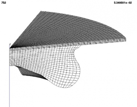
The K3prep pre-processor, included in KIVA-3V package [16], is used to build the computational grid for combustion simulations. A 60° sector grid is considered, because of the axial-symmetry of the combustion chamber and the homogeneous spatial distribution of the 6 injection holes. The geometry of the cylinder head is slightly simplified; however, the influence of the neglected geometric details, assessed on the standard Diesel engine, is very small, comparable to the experimental uncertainties. In designing the grid, particular care is devoted to get a good aspect ratio of cells, to correctly reproduce the actual geometry of the combustion chamber and to respect the compression ratio of the engine. A minimum of 5 cells layers is imposed in the squish region at Top Dead Center (TDC), while the typical cell size is about 0.5-1.0 mm. As found in previous analyses [15], these meshing criteria guarantee a good compromise between accuracy and computational demand. The computational grid is shown in Figure 1 and consists of about 110.000 cells at BDC and of about 25.000 TDC.
Initial and boundary conditions for the combustion simulations are derived from the experimental results, except for the initial flow field calculated in previous CFD 3D simulations [19].
Figure 1. Computational grid at top dead center
The natural gas is defined by a mixture of methane (≈95 %), ethane, propane and nitrogen, whereas Diesel oil is represented by the Diesel Oil Surrogate (DOS) model, in which liquid fuel properties are the same of real diesel oil, while fuel vapor is made up of a blend of n-heptane and toluene [15]. Finally, the combustion mechanism for Natural Gas/Diesel oil mixture includes 81 species and 421 reactions.
The experimental activity, used for the CFD-3D model validation, is performed at the dynamometer test bench of the Department of Engineering “Enzo Ferrari”, featuring an Apicom FR 400 BRV eddy-current brake (maximum power 260 kW, maximum torque 900 Nm) and the Apicom Horus software for system control and data acquisition. Along with the standard pressure and temperature transducers, three flow meters are used to measure the consumption of both Diesel and NG, as well as the combustion air flowrate. Moreover, the MRU VARIO plus Industrial analyzer is applied to measure the concentration of: O2, CO, CO2, NO, NO2, HC. A high frequency indicating system is installed for recording in-cylinder pressure traces; the system is made up of a Kistler piezoelectric transducer, installed on one cylinder in place of the glow plug, a charge amplifier and an optical encoder. The National Instruments Compact RIO hardware and the Alma Automotive software (Obi) are used to acquire the in-cylinder pressure traces and to monitor the related parameters, calculated in real time [15].
The Diesel engine under investigation is modified installing four NG injectors with a nominal flow rate of 1.5 g/s at 3 bar. The injectors are positioned on the engine inlet pipe, just downstream of the intercooler and about 500 mm before the intake manifold. This long distance guarantees a homogeneous air-NG mixture within the intake manifold, and a uniform distribution among the 4 cylinders. The position of the injectors is designed in order to promote air-NG mixing [15].
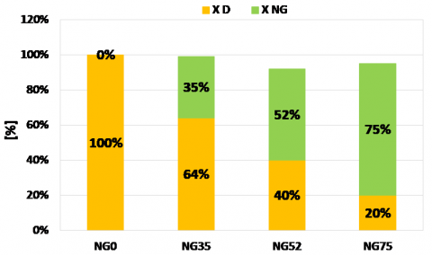
The work presented in this paper is focused on four cases, at 3000 rpm and 265 Nm, which differ for the shares of Diesel oil and NG injected within the cylinders. The energy introduced with Diesel oil and NG in DF mode is evaluated as a fraction of the energy entering with the Diesel fuel in Conventional Diesel (CD) mode, using the following equations:
$X_{D}[\%]=\frac{m_{D, D F}}{m_{D, C D}} \cdot 100$ (2)
$X_{N G}[9 / 0]=\frac{m_{N G} \cdot L H V_{N G}}{m_{D, C D} \cdot L H V_{D}} \cdot 100$ (3)
The cases are named after the percentage of energy introduced by means of NG. Therefore, CD mode corresponds to NG0, while NG35, NG52 and NG75 are the three DF operating conditions, at 35%, 52% and 75% of NG energy. All the DF cases are obtained by optimizing the Diesel injection strategy. The details of calibration are reviewed in [15].
Figure 2 shows the contributions of Diesel fuel and NG in terms of energy (evaluated by means of equations 2 and 3) for the four cases mentioned above. It should be noted that the total energy provided in DF mode is slightly lower than the one required in CD mode, despite the same brake torque output. This outcome demonstrates that BTE may be improved when passing from CD to DF operations.
Figure 2. Share of energy provided by each fuel in the experimentally optimized DF modes. Operating condition: 3000 rpm, BMEP=12 bar
In order to get accurate predictions from any CFD-3D combustion simulation it’s fundamental to calibrate the model with the support of a set of experimental data. These data should cover different operating conditions and include the measure of in-cylinder pressure and exhaust gas raw composition. A unique setting of calibration parameters must be used for all the investigated cases.
As well known, from the analysis of the ensemble averaged cylinder pressure it’s possible to get information about combustion, in particular the rate of heat release (RoHR) can be calculated. However, the value of this parameter is affected by the hypotheses on heat transfer and/or gas properties. Therefore, the RoHR curves should not be considered as an absolute reference for CFD model calibration. For this purpose, it’s better to assume the parameters that can be directly measured: the ensemble average cylinder pressure, along with the exhaust concentrations of NO+NO2=NOx, CO, CO2 and HC. The measure of the last pollutant is the most critical for the analyzer employed in the study, being its accuracy a little bit low (±10 %).
As far as the measure of soot is concerned, the experimental values are not used for the calibration of the CFD model, since the experimental accuracy is too poor, especially when the engine operates with small amounts of diesel fuel and the soot concentrations are very low.
The model calibration mainly consists in finding the best setting for the parameters related to the diesel injection curves (given the experimental values of start of injection, rail pressure and energization times), and to Diesel fuel atomization.
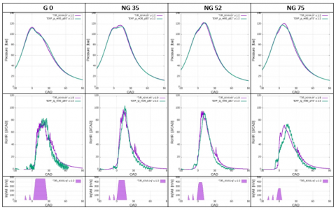
Figure 3 shows a comparison between predicted and measured in-cylinder pressure and Rate of Heat Release (RoHR) curves along with the injection laws for the four simulated operating points. The results of the numerical simulations are in very good agreement with experimental data.
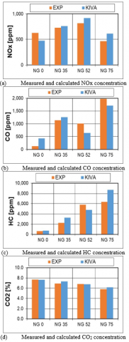
Figures 4 compares experimental and numerical results in terms of exhaust gas composition. As far as NOx emissions are concerned, the calibrated model tends to slightly overestimate this pollutant, in particular for high rates of NG. However, the trend of NOx concentration as a function of NG rate is correctly predicted. In CD mode, without NG, NOx emissions are slightly underestimated.
Considering CO and HC emissions, as NG rate increases, a significant increment of these pollutants is experimentally observed, as expected [15]. Again, even if the absolute values are affected by an error, the trend predicted by KIVA agrees quite well with the experimental one.
DF combustion leads also to a reduction of CO2 emissions, due to the lower C/H ratio of NG, sometimes combined with higher BTEs. The reduction of CO2 emissions in DF mode is well predicted by the simulation, as shown in Figure 4.
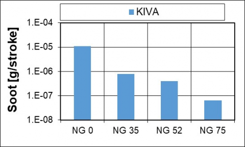
As previously mentioned, experimental soot emissions are not reported, because the soot concentration in the DF modes is so small that all the measures are very close to the lower threshold of the instrument. On the one hand, this outcome demonstrates the effectiveness of DF combustion for soot reduction; on the other hand, no reliable data for the numerical model validation are available. However, it may be noticed from Figure 5 that the strong reduction of Soot emissions observed during experimental tests is properly predicted also by simulations.
Figure 3. Comparison between experimental and numerical results in terms of in-cylinder pressure (first row) and Rate of Heat Release (RoHR, second row). The third row shows the diesel injection velocity, calculated on the basis of experimental energization duration, rail pressure and phasing
Figure 4. Comparison between experimental and numerical results in terms of gaseous emissions concentrations
Figure 5. Soot concentration calculated by KIVA
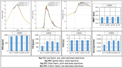
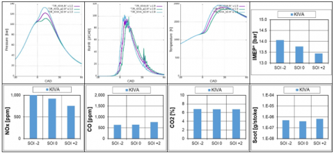
The calibrated KIVA model is applied to study the effect of different injection strategies. In details, two different variations of the original injection law are investigated, considering the DF combustion intermediate case, i.e. NG52. First, pre and pilot injections are alternatively suppressed and the duration of main injection is proportionally increased, in order to maintain constant the fuel injected mass. Then, the injection timing is shifted by steps of 2 Crank Angle Degrees (CAD), in both directions. Figures 6 and 7 show simulation results for the two cases in terms of indicated parameters (in-cylinder pressure and temperature and Rate of Heat Release), Gross Indicated Mean Effective Pressure (referred to as IMEP*, defined as the specific indicated work, calculated between IVC and EVO) and emissions (NOx, CO, CO2 and Soot). Looking at Figures 6 and 7, the following considerations are made.
CO, CO2 and Soot emissions are about the same, when injection timing is changed.
Figure 6. Influence of injection strategies on DF combustion of the NG52 operating point in terms of in-cylinder pressure, Rate of Heat Release, in-cylinder temperature, gross Indicated Mean Effective Pressure and emissions
Figure 7. Influence of injection timing on DF combustion of the NG52 operating point in terms of in-cylinder pressure, Rate of Heat Release, in-cylinder temperature, gross Indicated Mean Effective Pressure and emissions
A comprehensive experimental campaign, carried out on a light duty Diesel engine operating in standard and dual fuel mode, provided the basis for the calibration and validation of a CFD-3D dual fuel combustion model. In particular, four operating points are considered, keeping constant engine speed (3000 rpm) and load (BMEP=12 bar): NG0 (corresponding to the standard Diesel mode), NG35, NG52 and NG75 (with a 35, 52 and 75% of fuel energy provided by NG). For each case, in-cylinder pressure trace and exhaust gas concentrations (HC, CO2, CO, NOx) are measured and the results are compared to the parameters yielded by the numerical model.
It is found that the calibrated KIVA model is able to predict very accurately the average cylinder pressure, as well as the dependence of exhaust gas composition on the NG rate. In terms of absolute values, the numerical accuracy on emissions is less good than on cylinder pressure and combustion rates; however, the calibrated model is sound enough to be safely used in the study of this type of dual fuel combustion.
The most important parameter of Diesel injection appears to be the timing, whereas the presence of pilot and pre injections plays a much less relevant role.
|
BDC |
Bottom Dead Center |
|||
|
BMEP |
Brake Mean Effective Pressure |
|||
|
BTE |
Brake Thermal Efficiency |
|||
|
CAD |
Crank Angle Degrees |
|||
|
CD |
Conventional Diesel |
|||
|
CFD |
Computational Fluid Dynamics |
|||
|
CI |
Compression Ignition |
|||
|
CO |
Carbon monoxide |
|||
|
CO2 |
Carbon Dioxide |
|||
|
DF |
Dual Fuel |
|||
|
DOS |
Diesel Oil Surrogate |
|||
|
EGR |
Exhaust Gas Recirculation |
|||
|
HC |
Unburnt hydrocarbons |
|||
|
IMEP |
Indicated Mean Effective Pressure |
|||
|
LHV |
Lower Heating Value |
|||
|
m |
mass |
|||
|
NG |
Natural Gas |
|||
|
NO |
Nitrogen monoxide |
|||
|
NO2 |
Nitrogen dioxide |
|||
|
NOx |
Nitrogen Oxides |
|||
|
RoHR |
Rate of Heat Release |
|||
|
SI |
Spark Ignition |
|||
|
TDC |
Top Dead Center |
|||
|
X |
Fraction of energy introduced by a fuel in dual fuel mode |
|||
|
Subscripts
|
|
|
||
|
CD |
Conventional Diesel |
|
||
|
D |
Diesel |
|
||
|
DF |
Dual Fuel |
|
||
|
NG |
Natural Gas |
|
||
[1] Zhan, N.Y., Gao, Z., Deng, Y.F. (2018). Diffusion of vehicle exhaust pollutants in typical street canyons. International Journal of Heat and Technology, 36(3): 835-839. https://doi.org/ 10.18280/ijht.360308
[2] Transport for London website (tfl.gov.uk), Low Emission Zone, https://tfl.gov.uk/modes/driving/low-emission-zone?intcmp=2261, Retrieved April 18, 2019.
[3] Reuters website (www.reuters.com), R. Bousso, European diesel car sales plummet, https://www.reuters.com/article/europe-diesel/european-diesel-car-sales-plummet-iea-idUSL8N1WS22L, Retrieved April 18, 2019.
[4] BBC website (www.bbc.com), M. McGrath, Four major cities move to ban diesel vehicles by 2025, https://www.bbc.com/news/science-environment-38170794, Retrieved April 18, 2019.
[5] Shah, A., Thipse, S.S., Tyagi, A., Rairikar, S.D., Kavthekar, K.P., Marathe, N.V., Mandloi, P. (2011). Literature review and simulation of dual fuel diesel-CNG engines (No. 2011-26-0001). SAE Technical paper.
[6] Nithyanandan, K., Zhang, J., Li, Y., Meng, X., Donahue, R., Lee, C.F., Dou, H. (2016). Diesel-like efficiency using compressed natural gas/diesel dual-fuel combustion. Journal of Energy Resources Technology, 138(5): 052201. https://doi.org/10.1115/1.4032621
[7] Liu, J., Yang, F., Wang, H., Ouyang, M., Hao, S. (2013). Effects of pilot fuel quantity on the emissions characteristics of a CNG/diesel dual fuel engine with optimized pilot injection timing. Applied Energy, 110: 201-206. https://doi.org/10.1016/j.apenergy.2013.03.024
[8] Shu, J., Fu, J., Liu, J., Zhang, L., Zhao, Z. (2018). Experimental and computational study on the effects of injection timing on thermodynamics, combustion and emission characteristics of a natural gas (NG)-diesel dual fuel engine at low speed and low load. Energy Conversion and Management, 160: 426-438. https://doi.org/10.1016/j.enconman.2018.01.047
[9] Cantore, G., Mattarelli, E., Rinaldini, C.A., Savioli, T., Scrignoli, F. (2019). Experimental validation of a CFD-3D model for analyzing dual fuel (CNG/Diesel) combustion. TECNICA ITALIANA-Italian Journal of Engineering Science, 63(2-4): 381-385. https://doi.org/10.18280/ti-ijes.632-438
[10] Wei, L., Geng, P. (2016). A review on natural gas/diesel dual fuel combustion, emissions and performance. Fuel Processing Technology, 142: 264-278. http://dx.doi.org/10.1016/j.fuproc.2015.09.018
[11] Papagiannakis, R.G., Rakopoulos, C.D., Hountalas, D. T., Rakopoulos, D.C. (2010). Emission characteristics of high speed, dual fuel, compression ignition engine operating in a wide range of natural gas/diesel fuel proportions. Fuel, 89(7): 1397-1406. https://doi.org/10.1016/j.fuel.2009.11.001
[12] Imran, S., Emberson, D.R., Diez, A., Wen, D.S., Crookes, R.J., Korakianitis, T. (2014). Natural gas fueled compression ignition engine performance and emissions maps with diesel and RME pilot fuels. Applied Energy, 124: 354-365. https://doi.org/10.1016/j.apenergy.2014.02.067
[13] Carlucci, A.P., de Risi, A.D., Laforgia, D., Naccarato, F. (2008). Experimental investigation and combustion analysis of a direct injection dual-fuel diesel–natural gas engine. Energy, 33(2): 256-263. https://doi.org/10.1016/j.energy.2007.06.005
[14] Kusaka, J., Okamoto, T., Daisho, Y., Kihara, R., Saito, T. (2000). Combustion and exhaust gas emission characteristics of a diesel engine dual-fueled with natural gas. JSAE Review, 21(4): 489-496. https://doi.org/10.1016/S0389-4304(00)00071-0
[15] Mattarelli, E., Rinaldini, C.A., Savioli, T. (2018). Dual fuel (natural gas / diesel) for light-duty industrial engines: A numerical and experimental investigation. In Natural Gas Engines: For Transportation and Power Generation, Energy, Environment, and Sustainability. Springer, Singapore, pp. 297-328. https://doi.org/10.1007/978-981-13-3307-1_11
[16] Amsden, A.A. KIVA-3V: A Block-structured KIVA Program for Engines with Vertical or Canted Valves. (1197) LA-133 13-MS.
[17] Golovitchev, V.I., Montorsi, L., Rinaldini, C.A., Rosetti, A. (2006). CFD combustion and emission formation modeling for a HSDI diesel engine using detailed chemistry. In ASME 2006 Internal Combustion Engine Division Fall Technical Conference, pp. 349-358. https://doi.org/10.1115/ICEF2006-1506
[18] Golovitchev, V.I., Nordin, N., Jarnicki, R., Chomiak, J. (2000). 3-D diesel spray simulations using a new detailed chemistry turbulent combustion model. SAE Transactions, 1391-1405. https://doi.org/10.4271/2000-01-1891
[19] Mattarelli, E., Rinaldini, C.A., Golovitchev, V.I. (2014). CFD-3D analysis of a light duty Dual Fuel (Diesel/Natural Gas) combustion engine. Energy Procedia, 45: 929-937. https://doi.org/10.1016/j.egypro.2014.01.098
[20] Golovitchev, V. I., Imren, A. (2013). Development of dual fuel combustion models for direct injected heavy duty diesel engines. Diesel fuels: characteristics, performances and environmental impacts. Nova Pusblisher.