OPEN ACCESS
This paper aims to disclose the effect of suction nozzle structure on the RC suction capacity of DTH drill bit. For this purpose, three different types of suction nozzles were developed for the DTH drill bit. Then, the CFD software was adopted to simulate the fluid movement in a hole and the DTH drill bit. The results show that type three ranked first in terms of RC suction capacity, while type two came at the bottom. Then, the entrainment ratio was introduced to quantify the RC capacity. The results show that the RC capacity of type three is about 6 times of that of the other two types of nozzles. Our research opens up a new direction for future engineering practices.
down-the-hole (DTH) hammer drilling, reverse circulation (RC), drill bit, computational fluid dynamics (CFD)
Pneumatic down-the-hole (DTH) drilling is a rotary percussion drilling technique targeted at hard rocks [1]. In hard formations, this technique boasts better penetration rate and straighter bore hole than the other drilling methods [2]. The drilling process is driven by the percussive force on the drill bit, which comes from the high-pressure (HP) compressed air released by the DTH hammer. During drilling, the cuttings are traditionally blown clear through a hole outside the DTH hammer.
By contrast, all cuttings are collected through the central passage in the reverse circulation (RC) hammer. The RC hammer, as an improved DTH hammer, can achieve high recovery rate of typical samples, accurate sampling of low-grade ores, and continuous sampling from hole bottom. More importantly, the improved technique ensures the straightness of bore holes in broken formations, and prevents the loss circulation in the penetration through unconsolidated formations. Compared with traditional DTH hammer, the RC hammer is cost effective, highly productive and environmental friendly [3-4]. Thanks to the many advantages, the RC hammer has been widely implemented in mineral exploration and drilling around the world.
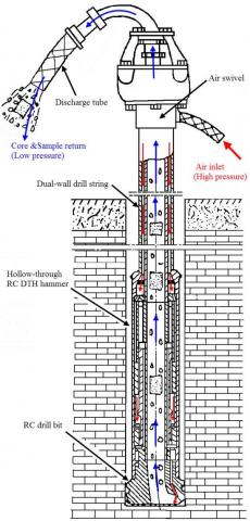
As shown in Figure 1, the pneumatic RC DTH hammer drilling system consists of a special drill bit, a hollow RC DTH hammer, a dual-wall drill string, an air swivel, an air inlet tube, and an air discharge tube [4,5]. In the course of drilling, the HP compressed air flows through the air inlet tube, the air swivel, the annulus between the inner and outer tubes of the drill string, the hollow hammer and the drill bit. There is no cross contamination with other parts of the hole, as the exhaust air from the hammer carries the cuttings and sample hoses to the surface through the steel inner tubes. In the end, the drilling system provides virtually uncontaminated dry cuttings for geologists.
The reverse circulation of air at the hole bottom depends on the nozzle design of the drill bit [5]. The nozzles on most drill bits are oriented at the hole bottom or side face. The HP compressed air jetting from these nozzles moves much faster than sound [6]. In most cases, the air hits on the hole wall, and carries cuttings into the central passage of the drill bit. However, parts of the air sometimes may be leaked to the surface through the annulus between the drill bit and the hole wall, leading to the loss of samples. In this case, the structure of drill bit must be improved to enhance the efficiency of reverse circulation.
Therefore, a new drill bit was designed recently for the RC hammer drilling system based on ejector theory. The structure of the drill bit is presented in Figure 2. The drill bit contains two types of nozzles: the flushing nozzles vertical to hole bottom and connected to diffuser groove, and the tip-tilted suction nozzles pointing towards the central passage of the drill bit. In the new structure, the HP compressed air is divided into two parts after arriving at the annulus between the spline shank and spline sleeve of the drill bit. One part sweeps the cuttings and cools the drill bit through the flushing nozzles, and the other part flows towards the central passage and entrains the air adjacent to the suction nozzles. The suction jets immediately alter the pressure in the central passage, and lower the pressure under the suction nozzles. Under the pressure difference between the central passage and the annulus, the cuttings are continuously drawn into the central passage and carried to the surface. The pressure difference is positively correlated with the amount of air sucked into the passage, i.e. the RC suction capacity of the drill bit.
Figure 1. Schematic diagram of the RC DTH hammer drilling system
Figure 2. Structural schematic diagram of the RC DTH hammer drill bit
Obviously, the RC suction capacity of the drill bit directly hinges on the structure of the suction nozzles. Much research has been done to ascertain the relationship between the RC suction capacity and suction nozzle structure. For example, Yin et al. [5] presented a RC DTH hammer drill bit with jet nozzles based on ejector theory. Behaviour of composite plate due to low velocity impact with drop weight machine was studied by some researches in past [7-9]. Wang et al. [10] improved a RC drill bit by changing the nozzle orientation towards the central passage, and obtained continuous sampling at a high recovery rate in subsequent experiments. Hao et al. [11] optimized the structural parameters of jet nozzles and flushing nozzles with Visual Basic. Relying on computational fluid dynamics (CFD) software, Zhu et al. [12] observed that the angle of suction nozzles may affect the pressure and velocity field, and experimentally determined the effect of nozzle angle on the RC capacity of the drill bit. To sum up, all these studies are concentrated on the suction nozzles with ribs between every two flat keys of the spline. However, none of them tackled suction nozzles with other structures. In this research, three different types of suction nozzles were designed to disclose the effect of suction nozzle structure on the RC suction capacity of the drill bit. The first type of suction nozzle has ribs between every two flat keys of the spline; the second type has ribs in every flat key of the spline; the third type has ribs in the bit head. Specifically, the RC suction capacity of each type of suction nozzle was investigated by CFD and experiments, and assessed by the volumetric flow rate of the air sucked into the central passage from the annulus.
The working mechanism of an ejector is based on Venturi effect, a special case of Bernoulli’s principle. There are four basic parts of an ejector: a nozzle, a suction chamber, a mixing chamber and a diffuser (Figure 3).
Figure 3. Diagram of a typical ejector
During ejection, the HP motive fluid moves slowly through the nozzle, and is converted to a high velocity fluid, leaving a low-pressure zone near the nozzle. The low pressure draws the suction fluid into the mixing chamber, where the fluid is mixed with the motive fluid [13, 14]. In essence, the pressure energy of the motive fluid is converted at the nozzle to kinetic energy in the form of velocity head. Later, as the mixed fluid expands in the diffuser, the kinetic energy is converted back to pressure energy. The change from pressure head to velocity head is the basis of the jet vacuum principle [15].
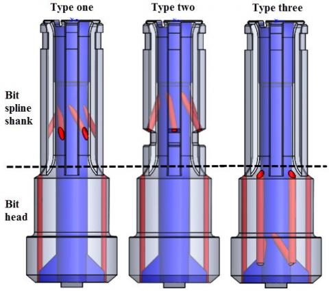
In this study, the ejector theory is adopted to design a RC DTH hammer drill bit with desired RC capacity. Note that every nozzle was regarded as an ejector in the design. Following the ejector theory, the suction nozzle design aims to create a low-pressure zone at hole bottom, such that the cuttings could be sucked into the central passage of the drill bit. As mentioned before, three different types of suction nozzles (Figure 4) were designed to disclose the effect of suction nozzle structure on the RC suction capacity of the drill bit. The first type of suction nozzle has ribs between every two flat keys of the spline; the second type has ribs in every flat key of the spline; the third type has ribs in the bit head.
Figure 4. Three design types of the suction nozzles
The RC DTH hammer drill bit has two parts: the bit spline shank and bit head. The bit spline shank contains six flat keys. For the drill bit, the number of flushing nozzles is fixed at 2, while the number of suction nozzles varies with the design (types 1 and 2: six; type 3: four). In light of previous experience, the cross-section area of each type of nozzle was set to 300mm2 to strike a balance between efficiency and economy. The dimensions of these nozzles are shown in Table 1.
Table 1. The specific measurements of the flushing and suction nozzles
|
|
Type one |
Type two |
Type three |
|
Diameter of flushing nozzle (mm) |
6 |
||
|
Number of flushing nozzles |
2 |
||
|
Diameter of suction nozzle (mm) |
7.2 |
8.8 |
|
|
Number of suction nozzles |
6 |
4 |
|
|
Total air cross sectional area (mm2) |
300 |
||
The CFD software offers a set of modelling and numerical methods for the simulation of fluids engineering systems. The software not only predicts the performance of a particular design, and offers suggestions to improve the current design. FLUENT is one of the most popular commercial CFD codes. In this study, FLUENT is introduced to analyse the physical properties of the fluid passing through the drill bits. The fluid performances of the three nozzle types were then contrasted to obtain the optimal design.
4.1 Computational domains and grid models
The simulations were carried out on a 108mm-diameter drill bit and a 114mm-diameter hole wall. The other parameters were set as follows: annulus clearance between bit head and hole wall (hereinafter referred to as the annulus clearance) was 4mm; the central passage diameter was 38mm; the distance between drill bottom and hole bottom (hereinafter referred to as the bottom distance) was 8mm. The hole bottom was simplified as a circular plane, and the tungsten carbide inserts of the drill bit were ignored.
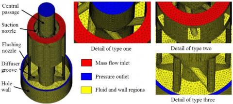
The computational domains were built with Solidworks software, and the grid models were generated by Hypermesh software. Figure 5 shows the computational domain and grid details of each type of nozzle. The computational domain covers the central passage, the suction nozzles, the flushing nozzles, two diffuser grooves, the bottom distance and the annulus clearance.
Figure 5. Computational domain and grid details of three types
The grid models detail the difference among the three types of nozzles. To maintain grid independence, all three grid models share the same minimum (0.5mm) and maximum grid sizes (2.5mm). The computational domain was meshed into unstructured tetrahedral grids, which allow the automatic, adaptive refinement on the complex geometries and regions. The three models have a total of 240,000 grid elements.
4.2 Material properties and boundary conditions
The working fluid of the RC DTH hammer drill bit is HP compressed air, whose fluid density varies violently with pressure changes. In this study, the HP compressed air is regarded as an ideal gas, which moves randomly without interacting with particles. The ideal gas obeys a simplified equation of the state of ideal gas [16]. Here, the FLUENT software relates density to static pressure with the ideal gas state equation, and the molecular weight is kept constant at 28.966 kg/mol.
Below is a detailed introduction to the boundary conditions. First, a boundary condition was configured to provide a pre-set mass flow rate at the inlet of the computational domain (the red plane in Figure 5). In our laboratory, the air flow rate of the air compressor was 6m3/min. Thus, the mass flow rate at the inlet was set to 0.1225 kg/s for the CFD simulation. Then, a boundary condition for pressure outlet was defined at the central passage and the annulus between the bit head and the hole wall (the blue planes in Figure 5). The pressure at the 2 outlets, directly connected to the atmosphere, was set to zero. In addition, a no-slip fixed boundary condition was designed for the walls to bound fluid regions (the yellow surfaces in Figure 5).
4.3 Solver settings
Despite the compressibility, the working fluid in the drill bit is unsteady and subject to multiple phases in the actual drilling process. Hence, the steady flow analysis was introduced to roughly assess the RC suction capacity of the drill bit.
The pressure-based solver in FLUENT was employed to discretize the momentum, continuity and energy equations during the simulation of the HP compressed air flow [16, 17].
The FLUENT software provides many turbulence models for simulations [17]. The most proper model should be selected against the flow physics, accuracy requirement, computing resources and simulation time. Since the RC DTH hammer drill bit was design with multiple ejectors, it is worthwhile to refer to the previous CFD simulations of ejector flow fields [18-23] before selecting the turbulence model. After long deliberation, the author selected the realisable k-ε model for the simulation. The term “realisable” means the model satisfies certain mathematical constraints on the Reynolds stress, and obeys the physics of turbulent flows [24]. The model makes accurate prediction of the spread rate of jet flows and excels in separation and recirculation [25].
The pressure-based solver resolves flow problems in a coupled manner. The FLUENT offers five pressure-velocity coupling algorithms. Among them, the SIMPLE algorithm was employed to enforce mass conservation and obtain the pressure field based on the relationship between velocity and pressure corrections [26]. The second-order upwind discretization was adopted to calculate the turbulent kinetic energy and the turbulent dissipation rate. Together with tetrahedral grids, the selected plan can achieve very accurate results.
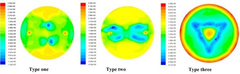
Figure 6 displays the CFD simulated contours of the bottom static pressure distributions of the three types of nozzles. It is clear that type three had the lowest mean static pressure, followed in ascending order by type one and type two. The lower the bottom pressure, the easier for the cuttings to enter the central passage and move towards the surface. In addition, type three boasted the largest proportion of low pressure area (the green or blue area in Figure 6) among the three types of nozzles. The results indicate that type 3 has the best entraining performance.
Figure 6. Contours of static pressure distribution at the bottom of the three type bits
Figure 7 describes the static pressure distribution along the axial direction of the central passage. It can be seen that type three had a much lower static pressure than the other types. The valley of the static pressure of this type of nozzle appeared at about -0.275m, near the outlets of the nozzle. Type one had a slightly better performance than type two.
Figure 8 shows the flow velocity distribution along the axial direction of the central passage. The three curves bear much resemblance to those in Figure 7 in variation trend. The phenomenon can be interpreted by the Bernoulli’s equation: the flow velocity, an indicator of dynamic pressure, is positively correlated with the dynamic pressure, and negatively with the static pressure.
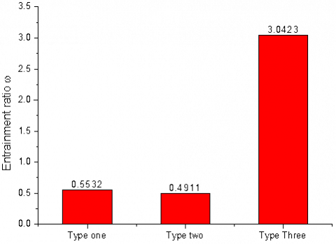
To quantify the RC capacity of the DTH hammer drill bit, the entrainment ratio was proposed and defined as mS/mP, where mS is the mass flow rate of suction air and mP is the total mass flow rate of the input air (0.3615kg/s). As shown in Figure 9, the entrainment ratio of type three far exceeded that of the other two types of nozzles. To be specific, the RC capacity of type three is about 6 times of that of the other two types of nozzles.
Figure 7. Distribution of static pressure along the axial direction of the center passage
Figure 8. Distribution of flow velocity magnitude along the axial direction of the center passage
Figure 9. Comparison of reverse circulation performance of the three types of the down-the-hole hammer drill bits
In this paper, three different types of suction nozzles were developed to disclose the effect of suction nozzle structure on the RC suction capacity of DTH drill bit. Then, the CFD software was adopted to simulate the fluid movement in a hole and a DTH drill bit with the three types of nozzles. The results show that type three ranked first in terms of RC suction capacity, while type two came at the bottom. Then, the entrainment ratio was introduced to quantify the RC capacity. The results show that the RC capacity of type three is about 6 times of that of the other two types of nozzles. Our research opens up a new direction for future engineering practices.
The authors gratefully acknowledge the support of China Geological Survey Project (No. 12120113096900) for this work. The authors are also grateful to the reviewers for their helpful advices.
[1] Chiang L.E., Elias D.A. (2000). Modeling impact in down-the-hole rock drilling, International Journal of Rock Mechanics and Mining Sciences, Vol. 37, No. 4, pp. 599-613. DOI: 10.1016/S1365-1609(99)00124-0
[2] Bu C.G., Qu Y.G., Cheng Z.Q., Liu B.L. (2009). Numerical simulation of impact on pneumatic DTH hammer percussive drilling, Journal of Earth Science, Vol. 20, No. 5, pp. 868-878. DOI: 10.1007/s12583-009-0073-5
[3] Yin K., Wang M.S., Peng J.M., Wang R.S. (2010). Percussive-rotary drilling, Geological Publishing House, Beijing, China.
[4] Bo K., Yin K., Peng J.M. (2011) Reverse circulation DTH hammer drilling technique, Global Geology, Vol. 14, No. 4, pp. 259-264. DOI: 10.3969/j.issn.1673-9736.2011.04.08
[5] Zhang Z.P., Yin K., Jiang R.Q., Sun Y.H. (2007). The New Technology of Rock and Soil Drilling Engineering, Geological Publishing House, Beijing, China.
[6] Geng R.L. (1995). Air Drilling with Multiple-Technique, Geological Publishing House, Beijing, China.
[7] Ansari M.M., Chakrabarti A., Iqbal M.A. (2016). Effects of impactor and other geometric parameters on impact behavior of FRP laminated composite plate, Modelling, Measurement and Control A, Vol. 89, No. 1, pp. 25-44.
[8] Song J., Chen F.Y. (2015). Calculation model for thermo-mechanical coupling and 3D numerical simulation for concrete tower of cable-stayed bridge, Mathematical Modelling of Engineering Problems, Vol. 2, No. 1, pp. 9-12. DOI: 10.18280/mmep.020103
[9] Zhu W., Li C.Y., Xu X.Z., Liang X. (2014). Analysis on the structure transformation of landing craft, Mathematical Modelling of Engineering Problems, Vol. 1, No. 2, pp. 7-10. DOI: 10.18280/mmep.010202
[10] Wang M.S., Yin K., Chen B.Y., Jia L., Application of hollow-through DTH to completed strata and improvement of reverse circulation drilling bit, Coal Geology & Exploration, Vol.33, No. 5, pp. 32-39.
[11] Hao S.Q., Yin K., Huang H.W. (2008). Improvement and optimized design on the structure of pneumatic down-the-hole hammer reverse circulation drilling bit, Exploration Engineering (Rock & Soil Drilling and Tunneling), Vol. 10, pp. 18-22.
[12] Zhu L.H., Yin K., Wang R.H., Liu J.L., Ren H. (2012). Angle research on inner orifice for suction type reverse circulation drill bit, Construction Machinery and Equipment, Vol. 43, No. 1, pp. 23-27.
[13] Bonnington S.T., King A.L. (1976). Jet Pumps and Ejectors: A State of the Art Review and Bibliography (2nd edition), British Hydromechanics Research Association Fluid Engineering, Cranfield, Bedford, UK.
[14] Keenan J.H., Neumann E.P. (1950). An investigation of ejector design by analysis and experiment, Journal of Applied Mechanics, Vol. 72, No. 3, pp. 299-309.
[15] Sun D.W., Eames I.W. (1995). Recent developments in the design theories and applications of ejectors - A review, Journal of the Institute of Energy, Vol. 68, No. 475, pp. 65-79.
[16] Ansys Inc. (2006). Fluent user’s guide, release 6.3.26. Lebanon, New Hampshire, USA.
[17] John D.J. (1995). Computational fluid dynamics: The basics with applications, McGraw Hill Companies Inc., New York, USA.
[18] Rusly E., Aye L., Charters W.W.S., Ooi A. (2005). CFD analysis of ejector in a combined ejector cooling system, International Journal of Refrigeration, Vol. 28, No. 7, pp. 1092-1101. DOI: 10.1016/j.ijrefrig.2005.02.005
[19] Szabolcs V., Oliveira A.C., Bogdan D. (2009). Numerical assessment of steam ejector efficiencies using CFD, International Journal of Refrigeration, Vol. 32, No. 6, pp. 1203-1211. DOI: 10.1016/j.ijrefrig.2009.01.007
[20] Bartosiewicz Y., Aidoun M., Mercadier Y. (2006). Numerical assessment of ejector operation for refrigeration applications based on CFD, Applied Thermal Engineering, Vol. 26, No. 5-6, pp. 604-612. DOI: 10.1016/j.applthermaleng.2005.07.003
[21] Sriveerakul T., Aphornratan S., Chunnanond K., Performance prediction of steam ejector using computational fluid dynamics: Part 1. Validation of the CFD results, International Journal of Thermal Sciences, Vol. 46, No. 8, pp. 812-822. DOI: 10.1016/j.ijthermalsci.2006.10.014
[22] Das A., Deb K., Bajerjee S., Bag R. (2017). A new method for tutorial gap identification towards students modeling, Mathematical Modelling of Engineering Problems, Vol. 4, No. 2, pp. 80-83.
[23] Tang L., Chen M.J. (2016). Image denoising method using the gradient matching pursuit, Mathematical Modelling of Engineering Problems, Vol. 3, No. 2, pp. 53-56. DOI: 10.18280/mmep.030201
[24] Pal S., Ghosh S., Bhattacharya S. (2017). Study and implementation of environment monitoring system based on MQTT, Environmental and Earth Sciences Research Journal, Vol. 4, No. 1, pp. 23-28. DOI: 10.18280/eesrj.040105
[25] Li Q.M., Cheng K., Yang X.Y. (2016). Economic and social analysis of haze reduction dilemma in China, Environmental and Earth Sciences Research Journal, Vol. 3, No. 1, pp. 14-22. DOI: 10.18280/eesrj.030103
[26] Li S., Zhang Y., Li Y., Liao R. (2015). Prediction of molar volume for pure compounds using Peng-Robinson equation of state, Environmental and Earth Sciences Research Journal, Vol. 2, No. 3, pp. 13-16. DOI: 10.18280/eesrj.020303