OPEN ACCESS
Numerical investigations are carried out in a three dimensional square duct with wedge shaped rib and groove turbulators on its top and bottom wall to examine the effect of geometric parameters on turbulent forced convective heat transfer and friction characteristics. The study is perofrmed for geometric parameters for orientation of turbulators, groove height, rib gap, turbulator length and pitchat Reynolds number ranging from 10000 to 30000. The constant heat flux boundary condition is specified at the entire surfaces of the duct. The smooth duct is validated with the correlations established by Dittus Boelter, Gnielinski, Blasius and Petukhov. For this numerical assessment, k-ϵ turbulence model with enhanced wall treatment is used. The thermal enhancement is reported in terms of Nusselt number (Nu), Darcy friction factor (f) and thermal enhancement factor (TEF). Both the heat transfer and friction loss are found sensitive to the changes in the geometric parameters.
darcy friction factor, forced convection, nusselt number, reynolds number, thermal enhancement factor
Design of low-cost compact heat exchanger is one of the biggest challenges in the engineering field. Many methods are adopted for the enhancement of heat transfer in industries like shell and tube heat exchangers, air-conditioning system, electronic cooling devices etc. Turbulators like rib, groove, twisted tapes, baffle, coil etc. are used to create boundary layer turbulence to distort the viscous sub-layer near wall region in order to increase the rate of heat transfer. These passive techniques are used by many investigators in recent years. Promvonge et al. [1] studied the thermal characteristics of turbulent flow in a constant heat flux channel mounted with differently shaped ribs in-parallel and staggered arrangement. They reported that the parallel arrangement provides more heat transfer rate and friction losses than the staggered one. Heat transfer characteristics of a wavy walled duct have been analyzed numerically by Ramgadia et al. [2]. Karthikeyan et al. [3] carried out an experimental investigation on developing turbulent flow and heat transfer in a convergent-divergent rectangular ribbed duct with an inclination angle of 10 to the y-axis using four different rib heights similar to the work of Wang et al. [4] and it has been reported that that the divergent duct gives better result in heat transfer enhancement for all rib heights. Promvonge et al. [5] found that the rise of blockage ratio leads to enhancement in heat transfer and friction losses in a square duct with inline 600 V– shaped ribs mounted on two opposite walls. Leung et al. [6] came out with the result that heat transfer augmentation attains its highest value at apex angle ɵ= 17.50 of a V-groove turbulator mounted on the walls of a triangular sectional duct. Eiamsa-ard et al. [7] performed a numerical investigation of turbulent forced convection in the two-dimensional periodic transverse grooves on the lower channel wall which is exposed to constant heat flux. They claimed that the groove channel provides a maximum gain of 1.33 on the thermal performance factor which is obtained for the case of B/H=0.75. Ahmed et al. [8] conducted a numerical simulation to investigate the effect of geometrical parameters on laminar flow and forced convection heat transfer characteristics in grooved micro-channel heat sinks similar to the analysis performed by Xia et al. [9]. Eiamsa-ard et al. [10] implemented an experimental investigation to examine the combined effects of rib-groove turbulators on the turbulent forced convection heat transfer and friction characteristics in a rectangular duct with rib-groove combinations like triangular rib-rectangular groove, rectangular rib-triangular groove and triangular rib-triangular groove. Heat transfer enhancement in a square duct using twisted tape of different twist ratios is investigated experimentally by Patil et al. [11]. They found that both Nusselt number and friction factor increase with a decrease in the twist ratio. Arslan et al. [12] executed an experimental investigation of flow and heat transfer in a rectangular cross-sectional duct with baffles mounted on its bottom wall at different inclination angles. Promvonge et al. [13, 14] performed both experimental and numerical investigation to analyze turbulent flow and heat transfer characteristics in a square duct fitted diagonally with an angle finned tape. The effect of duct aspect ratio on heat transfer and friction in a steam cooled ducts with 90° rib turbulators is studied numerically and experimentally by Shui et al. [15]. The study of Leung et al. [16] when investigated on a triangular duct with a square rib revealed that the Darcy friction factor of a duct increases linearly with increase in rib size. The effect of rib shape on turbulent forced convective heat transfer and friction characteristics are examined by Ahn et al. [17]. It was reported that the triangular ribs give the best thermal performance compared to other shapes like rectangular, circular, square, semi-circular etc. Thianpong et al. [18] carried through an experimental investigation on turbulent flow in a channel with isosceles triangular ribs. Kwon et al. [19] performed experimental analysis on a wavy duct with various corrugation angles to study the heat transfer and friction characteristics. Effects of groove geometry on heat transfer and fluid flow is studied numerically by Ramadhan et al. [20] and they claimed that best performance occurs with the lower depth-groove ratio.
So far, the main attention has been given on rib and groove turbulators that are inserted in the path of flow. In this report, the main objective is to analyze the effect of geometrical parameters of rib and groove turbulators on turbulent forced convective heat transfer and friction characteristics of a three-dimensional square duct. This numerical investigation is carried out at Reynolds number ranging from 10000 to 30000 with uniform heat flux boundary condition at all surfaces. The Nusselt number and friction factor of the smooth duct are validated with empirical relations. The measured data obtained from a numerical investigation using turbulators are compared with those from the smooth one.
ν= Kinematic viscosity, m2 s-1
2.1 Geometry of present problem
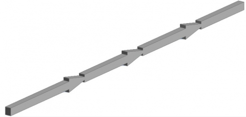
Figure 1 (a). Duct geometry in three dimensional view
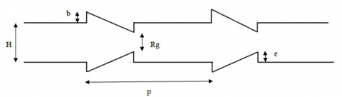
Figure 1 (b). Duct geometry in two dimensional view
The three-dimensional duct, with a square cross-section of height H of 10mm and length of 60H, is incorporated with rib and groove turbulators on both upper and lower walls. In this report, the geometric parameters such as orientation, groove height, rib gap, turbulator length and pitch are varied to study the effect on heat transfer characteristics with the variation of Reynolds number (Re) from 10000 to 30000. Measurements are taken for parallel and two nonparallel (with different shifting position of lower wall turbulators) arrangements of turbulators along with the variation in groove height, rib gap, turbulator length and pitch from 0.2H to 0.6H, 0.2H to 0.6H, 0.2H to 0.4H and 10H to 15H respectively to study their effect on heat transfer and friction characteristics. The sizes of the turbulators are identical to each other. The duct geometry is shown in both three dimensional and two-dimensional views in figure 1(a) and 1(b) respectively.
2.2 Mathematical modeling
The numerical simulation of three-dimensional square duct for forced convection is conducted under the following assumptions:
• Steady and three dimensional.
• The flow is turbulent and incompressible.
• Constant fluid properties.
• Body forces, radiation heat transfer, and viscous dissipation are ignored.
2.2.1 Governing equations
The governing equations for mass, momentum, and energy are needed to be considered for complete CFD analysis of the current rib-grooved channel. The present work of single phase model is governed by a steady three-dimensional form of continuity, time-averaged incompressible Navier- Stokes equations, and energy equation. The methodology used to solve these governing equations is described in the next section.
2.2.2 Standard k-ϵ model
The governing equations are written in the cartesian tensor system.
The continuity equation
$\frac{\partial\left(\rho u_{i}\right)}{\partial x_{i}}=0$ (1)
The momentum equation:
$\frac{\partial \rho u_{i} u_{j}}{\partial x_{j}}=-\frac{\partial p}{\partial x_{i}}+\frac{\partial}{\partial x}\left[\mu\left\{\frac{\partial u_{i}}{\partial x_{j}}-\rho \overline{u_{i} u_{j}}\right\}\right]$ (2)
where ρ is the density of the fluid, ui is the mean velocity component in the direction of xi, p is the pressure, µ is the dynamic viscosity and uʹ is the fluctuating component of velocity. Repeated indices indicate summation of one to three for the 3D problem.
Energy equation:
$\frac{\partial\left(\rho u_{i} T\right)}{\partial x_{i}}=\frac{\partial}{\partial x_{j}}\left[\left(\Gamma+\Gamma_{t}\right) \frac{\partial T}{\partial x_{j}}\right]$ (3)
where Г and Гt are molecular thermal diffusivity and turbulent thermal diffusivity respectively and are given by, $\Gamma=\frac{\mu}{\mathrm{Pr}}$; $\Gamma_{t}=\frac{\mu_{t}}{\mathrm{Pr}}$
For standard k-ϵ turbulent model two more partial differential equation is needed, one for turbulent kinetic energy (k) and the other for dissipation turbulent kinetic energy (ϵ).
The rate of change of k or ϵ + transport of k or ϵ by convection = transport of k or ϵ by diffusion + rate of production of k or ϵ - the rate of destruction of k or ϵ.
For turbulent kinetic energy,
$\frac{\partial(\rho k)}{\partial t}+\frac{\partial\left(\rho k u_{i}\right)}{\partial x_{i}}=\frac{\partial}{\partial x_{j}}\left[\frac{\mu_{t}}{\sigma_{k}} \frac{\partial k}{\partial x_{j}}\right]+2 \mu_{t} E_{i j} E_{i j}-\rho \in$ (4)
For rate of dissipation of kinetic energy,
$\frac{\partial(\rho \in)}{\partial t}+\frac{\partial\left(\rho \in u_{i}\right)}{\partial x_{i}}=\frac{\partial}{\partial x_{j}}\left[\frac{\mu_{t}}{\sigma_{e}} \frac{\partial \epsilon}{\partial x_{j}}\right]+C_{1 \epsilon} \frac{\epsilon}{k} 2 \mu_{t} E_{i j} E_{i j}-C_{2 \varepsilon} \rho \frac{\epsilon^{2}}{k}$ (5)
where Eij represents component of rate of deformation, µt represents eddy viscosity $\mathrm{y}=\rho C_{\mu} \frac{k^{2}}{\epsilon}$
The equations also consist of some adjustable constants σk, σϵ, C1ϵ and C2ϵ the values of these constants are as follows:
Cµ= 0.09, $\sigma_{k}$=1, $\sigma_{\in}$= 1.30, C1ϵ= 1.44, C2ϵ = 1.92 (6)
To obtain accurate prediction in the rib grooved duct, standard k-ϵ turbulence model was selected. To evaluate pressure field, the pressure velocity coupling algorithm SIMPLE was selected
2.3 Numerical procedure
The objective of the simulation is to find the Nusselt number and Darcy friction factor at Reynolds number ranging from 10000 to 30000. The Reynolds number based on hydraulic diameter is calculated as
$\mathrm{Re}=\frac{\mathrm{UD}_{\mathrm{h}}}{\mathrm{v}}$ (7)
The average heat transfer coefficient is calculated from heat input and the temperature difference between wall and bulk fluid. Heat flux Q is added uniformly to all faces of the duct. The surface or wall temperature is obtained on area weighted average method and the bulk fluid temperature is calculated as the average of inlet and outlet fluid temperature.
So, the average heat transfer coefficient is
$\mathrm{h}=\frac{\mathrm{Q}}{T_{w}-T_{f}}$ (8)
Tf= bulk fluid temperature = (T0+Ti)/2
T0 and Ti are the temperatures of the fluid at inlet and outlet respectively.
Tw= area weighted average temperature of surfaces
So, the Nusselt number of fluid= hDh/ k
To analyze the friction characteristic of the duct, Darcy friction factor is calculated at all Reynolds number.
Darcy friction factor
$(\mathrm{f})=\frac{8 \tau_{\mathrm{w}}}{\rho V^{2}}$ (9)
where V is the average outlet velocity.
The thermal enhancement factor (TEF) is defined as the ratio of heat transfer coefficient (h) of the augmented surface to that of a smooth surface.
TEF= h/h0= (Nu/Nu0)/(f/f0)1/3 (10)
where Nu0 and f0are a Nusselt number and friction factor for the smooth duct respectively.
2.4 Grid independence test
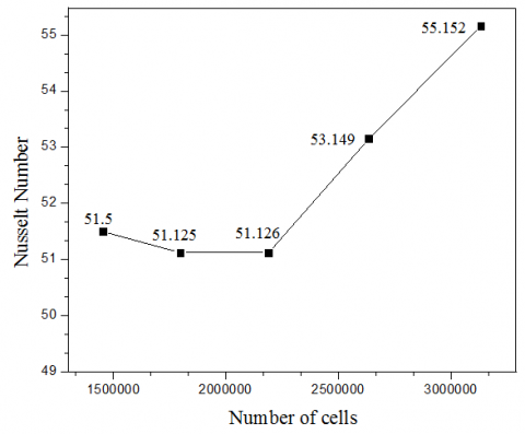
Figure 2(a). Grid independency test for Nusselt number
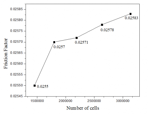
Figure 2(b). Grid independency test for friction factor
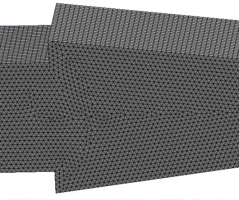
Figure 2(c). The final mesh adopted
In turbulence modeling, a parameter called y+ is needed to be taken care. It is a non-dimensional wall distance for wall bounded flow. y+ value is related to mesh generation process and hence it affects the CFD end results. It is of utmost importance to know the concept of wall y+ as it provides the idea about how the flow behaves near the wall. The choice of turbulence model is based on the value of y plus.
Grid independency test is executed to obtain most suitable grid size for computation. Prism elements with y+= 4 at the near wall regions are adopted to resolve the laminar sub-layer region. Grid independency test is performed for five different grid sizes which are 1452000, 1797120, 2190240, 2634240 and 3132000. At Reynolds number 20000 the values of Nusselt number and friction factor found to be consistent with the number of cell ranging from 1797120 and 2190240. Therefore, the grid system of 1797120 cells was adopted for the current computational model. The grid independency test for the Nusselt number and friction factor is shown in figure 2(a) and 2(b) respectively. The final mesh decided after the grid independency test is shown in figure 2(c).
2.5 Boundary conditions
The average velocity is varied from 14.58m/sec to 43.76m/sec based on the Reynolds number. No slip boundary condition at the wall and zero pressure gradients at exit are taken for the simulation. The constant mass flow rate of air with 300K is assumed in the flow direction. The constant heat flux at entire duct wall including the rib-groove turbulators surface is maintained at 5000 W/m2.
3.1 Validation of smooth duct
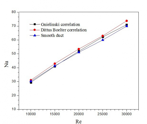
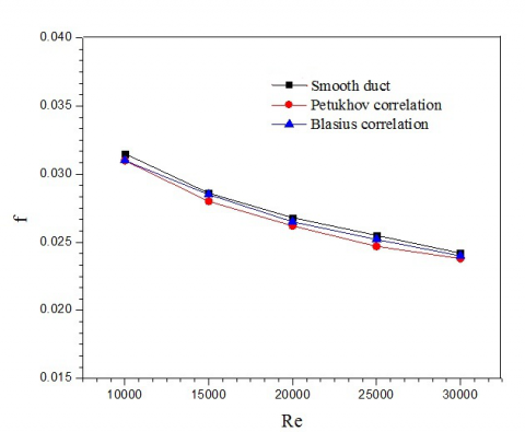
The results obtained from numerical analysis of smooth duct are validated with empirical correlation in terms of Nusselt number and Darcy friction factor. The Nusselt number is validated with Dittus Boelter and Gnielinski correlation while the Darcy friction factor is validated with Blasius and Petukhov correlation.
The Dittus Boelter correlation is
$\mathrm{Nu}=0.023 \mathrm{Re}^{0.8} \mathrm{Pr}^{0.4}(11)$ (11)
Gnielinski correlation is
$\mathrm{Nu}=\frac{(\mathrm{f} / 8)(\mathrm{Re}-1000) \mathrm{Pr}}{1+12.7(\mathrm{f} / 8)^{0 .5}\left(\mathrm{Pr}^{\frac{2}{3}}-1\right)}$ for 3000< Re< 5×10⁶ (12)
Blasius correlation is
$\mathrm{f}=0.316 \mathrm{Re}^{-0.25}$ (13)
Petukhov correlation is
$\mathrm{f}=[0.79 \ln (\mathrm{Re})-1.64]^{-2}$, for 3000< Re< 5×10⁶ (14)
In Fig. 2(a) and 2(b), the value of the Nusselt number and Darcy friction factor of the present problem using standard k-ϵ model is compared with that of empirical relations. A good agreement of Nusselt number and Darcy friction factor are found between the present numerical investigation and open literature [15, 19] for the smooth duct.
3.2 Heat transfer
Figure 3(a). Validation of Nusselt number with empirical correlations
Figure 3(b). Validation of Darcy friction factor with empirical correlations
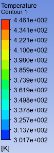
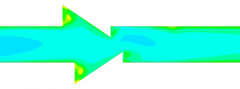
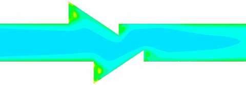
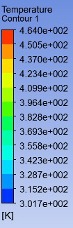
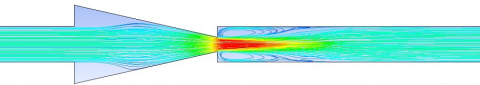
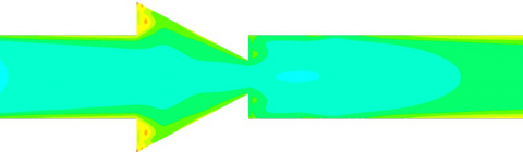
The most important characteristic parameter for analyzing the heat transfer behavior of the duct is its average Nusselt number. The present numerical simulation reveals that the rough duct provides a significant enhancement in the heat transfer rate over the smooth duct. The rate of heat transfer depends on thermal boundary layer thickness. Thermal boundary layer acts as an insulation layer in the path of heat transfer. In the groove region, the thermal boundary layer gets thicker at its peak due to which thermal resistance increases. But as the fluid strikes the inclined edge of the turbulator it moves back and generates eddies in the groove region. These eddies can guide the fluid towards the wall and thus cold fluid can take heat effectively from the hot wall which ultimately results in a decrease in thermal boundary layer thickness and increase the rate of heat transfer. Formation of eddies is also being observed in the region after the rib of the duct because of higher velocity at the minimum cross-section of the duct. Due to the formation of eddies in the rough duct, the heat transfer rate is significantly increased over the smooth duct. The temperature contour of the duct at the wall and turbulator is shown in Fig 4(b) and 4(c).
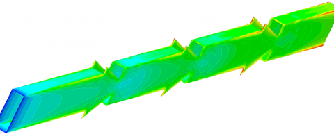
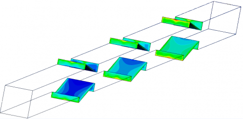
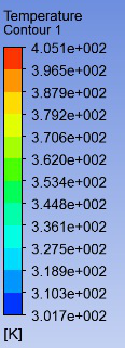
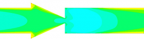
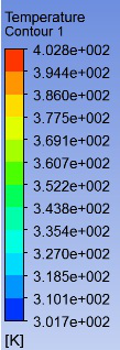
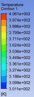
Figure 4(a). Temperature contour of the complete geometry at Re= 20000
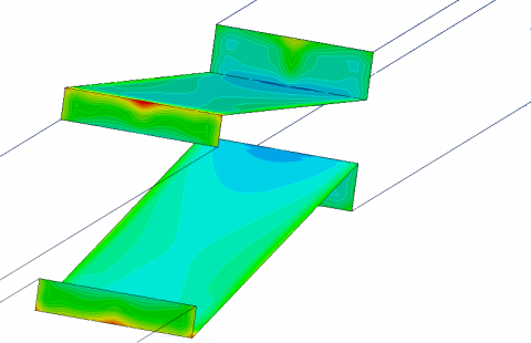
Figure 4(b). Temperature contour at turbulators at Re=20000
Figure 4(c). A close view of temperature contour at turbulators at Re= 20000
3.3 Effect of orientation of turbulators
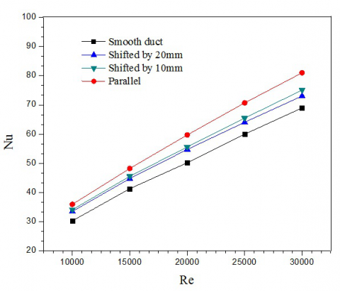
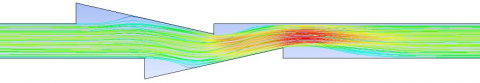
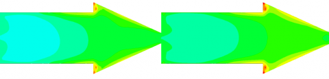
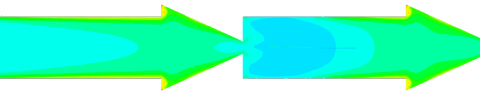
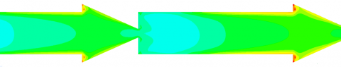
The present numerical simulation provides the value of the Nusselt number and Darcy friction factor for three orientations of rib-groove turbulators-parallel, lower turbulators shifted by 10mm and 20mm at a pitch of 150mm. The numerical study reveals that parallelly orientated turbulators give the maximum enhancement in both the Nusselt number and friction factor over the smooth duct, similar to the result of Ahmed [7] and Promvonge [19]. The mean increase in Nusselt number is around 18%, 10.3%, and 7.35% respectively. This is because of higher flow blockage (e/H= 0.3) which creates strong reverse flow in parallel arrangement resulting in better mixing of fluid particles. Again, in a parallel arrangement of turbulators, the structure of eddies is symmetry with the axial flow direction but in case of shifted position of turbulators, eddies generated on the flow is not symmetric with the flow direction as shown in Fig 6(a), 6(b) and 6(c). Symmetric eddies result in higher heat transfer enhancement. Also from temperature contour shown in Fig 7(a), 7(b) and 7(c), it is observed that the maximum temperature for parallel and two shifting positions of turbulators are 446K, 462K, and 464K. Hence, the parallel arrangement provides an excellent temperature gradient in the hot wall resulting in higher heat transfer rate.
Figure 5(a). Comparison of Nusselt number for different arrangement of turbulators
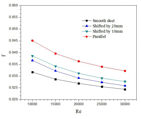
Figure 5(b). Comparison of friction factor for different arrangement of turbulators
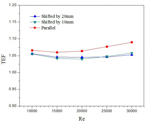
Figure 5(c). Comparison of thermal enhancement factor for different arrangement of turbulators
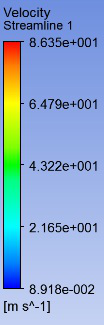
Figure 6(a). Velocity streamlines of duct for turbulators arranged in parallel arrangements at Re=20000
Figure 6(b). Velocity streamlines of duct when lower turbulators are shifted by 10cm at Re=20000
Figure 6(c). Velocity streamlines of duct when lower turbulators are shifted by 20cm at Re=20000
Figure 7(a). Temperature contour of duct for turbulators arranged in parallel arrangements at Re=20000
Figure 7(b). Temperature contour of duct when lower turbulators are shifted by 10cm at Re=20000
Figure 7(c). Temperature contour of duct when lower turbulators are shifted by 20cm at Re=2000
The friction factor of the paralleled oriented turbulators gives higher enhancement in friction factor compared to the shifted arrangement as shown in Fig 5(b). In all the three arrangements, there is a significant increase in friction factor over the smooth duct. The average increment in the friction factor is about 35%, 17%, and 15% respectively. This is due to the fact that the wall shear stress becomes high due to the minimum cross-sectional area of flow in case of parallel arrangement. Subsequently, the pressure drop also increases due to flow blockage on account of the parallel arrangement of the turbulators. Thermal enhancement factor is also calculated for all three orientations of turbulators and it is found the maximum for paralleled oriented turbulators.
The value of thermal enhancement factor is calculated for all three arrangements and is presented in Fig 5(c). It is noted that the parallel arrangement of turbulators provides the maximum TEF value at Reynolds number 30000. At this Re, the TEF values for parallel and shifting (by 1cm and 2cm) position of turbulators are1.09, 1.058 and 1.053 respectively.
3.4 Effect of groove height (b)
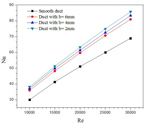
Investigations are carried out by varying the outer groove height from 2mm to 6mm at a pitch of 150mm with fixed rib gap of 4 mm. Thermal enhancements in terms of Nusselt number and Darcy friction factor are determined at all the three groove height. The numerical study reveals that both the Nusselt number and friction factor decrease with increasing the groove height. However, for all the three groove heights, the Nusselt number and Darcy friction factor are found the minimum for smooth one. The improvement of heat transfer for duct of groove height 2mm, 4mm and 6mm is found around 26%, 22.8%, and 18.6% respectively. For the duct of groove height 2mm, the vortices are created on wedge-shaped groove region due to reverse pressure gradient and sudden expansion as shown in Fig 9(a). These vortices can direct the fluid to flow to the groove walls. As a result, the thermal resistance is decreased and the cold fluid can effectively carry heat from the hot walls. With the increase of groove height, the stagnation region becomes larger due to the smaller included angle at its apex, which can deteriorate the heat transfer. Therefore, the stagnation region is found largest for groove height 6mm as shown in Fig 9(c). Because of this, the Nusselt number is found the minimum for groove height 6mm and maximum for 2mm. It can be observed from the temperature contour as shown in figure 10(a), 10(b) and 10(c) that the maximum temperature for groove height 2mm, 4mm and 6mm is 406K, 435.8K, and 446K respectively. So, the duct of 2mm groove height provides an excellent temperature gradient in the hot wall. This temperature gradient exists by reason of generation of eddies which causes effective heat exchange between thefluid and the wall by reducing the thermal boundary layer thickness.
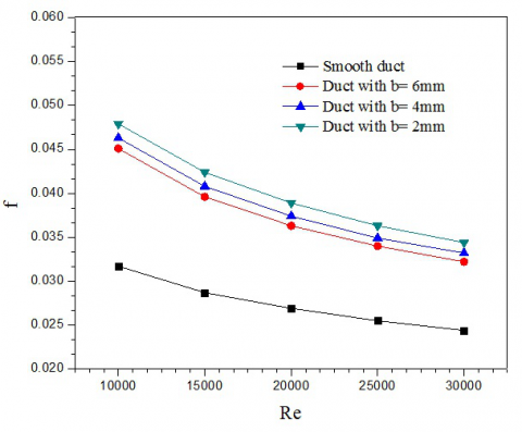
The enhancement in friction factor is about 45%, 40% and 36% over the smooth duct as shown in figure 8(b). This enhancement over the smooth duct is, on account of suppression of viscous sub layer, due to the presence of turbulators.
Figure 8(a). Comparison of Nusselt numberat different groove heights
Figure 8(b). Comparison of friction factor at different groove heights.
Figure 8(c). Comparison of thermal enhancement factor at different groove heights
The thermal enhancement factor for all the groove height is shown in figure 8(c). The maximum thermal enhancement factor is found for groove height 2mm at Reynolds number 30000 and its value is 1.13. This implies that the duct of 2mm groove height is more feasible than that of other two groove heights in terms of energy saving.
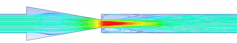
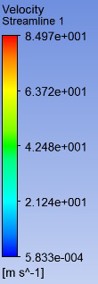
Figure 9(a). Velocity streamlines of duct for groove height 2mm at Re= 20000
Figure 9(b). Velocity streamlines of duct for groove height 4mm at Re= 20000
Figure 9(c). Velocity streamlines of duct for groove height 6mm at Re=20000
Figure 10(a). Temperature contour of duct for groove height 2mm at Re=20000
Figure 10(b). Temperature contour of duct for groove height 4mm at Re=20000
Figure 10(c). Temperature contour of duct for groove height 6mm at Re=20000
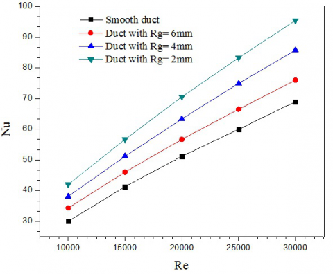
Figure 11(a). Comparison of Nusselt number at different rib gap
Figure 11(b). Comparison of friction factor at different rib gap
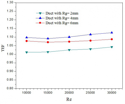
Figure 11(c). Comparison of thermal enhancement factor at different rib gap
3.5 Effect of rib gap (Rg)
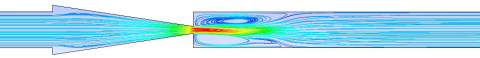
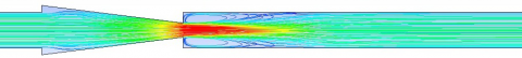
Figure 12(a). Velocity streamline of duct for rib gap 2mm Re= 20000
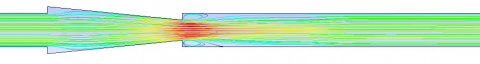
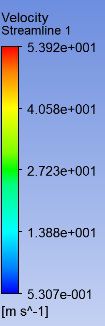
Figure 12(b). Velocity streamline of duct for rib gap 4mm Re= 20000
Figure 12(c). Velocity streamline of duct for rib gap 6mm Re= 20000
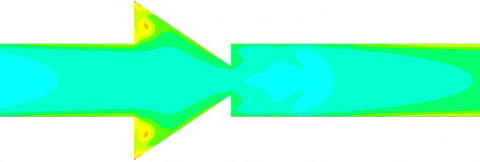
Figure 13(a). Temperature contour of duct for rib gap 2mm at Re= 20000
Figure 13(b). Temperature contour of duct for rib gap 4mm at Re= 20000
Figure 13(c). Temperature contour of duct for rib gap 6mm at Re= 20000
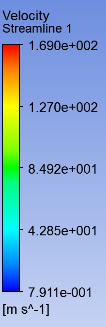
The different values of Nusselt number and Darcy friction factor are obtained from present numerical investigation for rib gaps 2 mm, 4 mm and 6 mm at a pitch of 150 mm keeping groove height fixed at 2 mm. The thermal enhancement is calculated in terms of Nusselt number and Darcy friction factor. A significant increase in both Nusselt number and friction factor over the smooth duct are found after introducing turbulators on its wall which increases the turbulent intensity of the flow by breaking the viscous sublayer near the wall. Also, this numerical study reveals that both the Nusselt number and friction factor are increased with a decrease in rib gap. This is because of higher flow blockage (e/H= 0.4) for the lowest value of rib gap which creates strong reverse flow and turbulent intensity resulting in better mixing of fluid particles. Again, decreasing rib gap increases the surface area exposed to the fluid flowing through the duct which increases higher heat transfer. The maximum velocities of flow for duct of rib gap 2mm, 4mm and 6mm are 170m/sec, 83.6m/sec, and 54m/sec respectively as shown in Figure 12(a), 12(b) and 12(c). Vortices of higher intensity and size are created in the region after the rib of the duct with smaller rib gap because of higher velocity of the fluid in the minimum cross-section. With the increase of rib gap to 4mm, the fluid velocity at this portion is not enough to create any effective and powerful vortices. For duct of 6mm rib gap, the size and intensity of the vortices created at the after-rib region are smaller than the other two. As a result, the heat transfer rate is decreased for the higher value of rib gap. It can be observed from the temperature contour shown in Fig 13(a), 13(b) and 13(c) that the maximum temperature recorded for rib gap 2mm, 4 mm and 6mm are 402K, 405K, and 406K respectively. So, the duct of 2mm rib gap provides excellent temperature gradient and consequently higher heat transfer coefficient. Hence, the Nusselt number enhancement is about 1.4, 1.25 and 1.12 times over the smooth duct for rib gap 2mm, 4mm and 6mm respectively. In addition, the improvement of heat transfer is found 40%, 25.6% and 12.3% over the smooth duct for rib gap 2mm, 4mm and 6mm respectively.
The enhancement in friction factor is found about 2.49, 1.45 and 1.12 times over the smooth duct. Also, the improvement in friction factor is about 149.5%, 45%, and 12% respectively. The friction factor is directly associated with the relative roughness or blockage ratio. So the lowest value of rib gap will have highest friction factor because of high value of blockage ratio. Subsequently, the pressure drop is increased due to flow blockage for duct of rib gap 2mm. The thermal enhancement factor is also calculated for all the three values of rib gaps. It is noted that the duct with 4mm rib gap provides better thermal performance than the other two.
The TEF is calculated for three rib gaps at all Reynolds numbers. Although the duct of 2mm rib gap provides maximum enhancement in term of heat transfer and friction loss, the duct of 4mm rib gap is found to be more feasible in terms of energy saving. The maximum TEF is found 1.13 at Reynolds number 30000.
3.6 Effect of turbulator length (l)
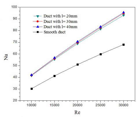
Figure 14(a). Comparison of Nusselt number atdifferent turbulator length
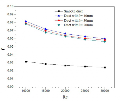
Figure 14(b). Comparison of friction factor atdifferent turbulator length
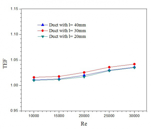
Figure 14(c). Comparison of thermal enhancement factor atdifferent turbulator length
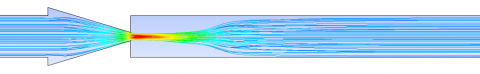
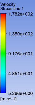
Figure 15(a). Velocity streamlines of duct for turbulator length 2mm at Re= 20000
Figure 15(b). Velocity streamlines of duct for turbulator length 3mm at Re= 20000
Figure 15(c). Velocity streamlines of duct for turbulator length 4mm at Re= 20000
Figure 16(a). Temperature contour of duct for turbulator length 2mm at Re= 20000
Figure 16(b). Temperature contour of duct for turbulator length 3mm at Re= 20000
Figure 16(c). Temperature contour of duct for turbulator length 4mm at Re= 20000
The present numerical simulation is carried out to examine the effect of length of turbulator on heat transfer characteristics by varying its value from 20 mm to 40 mm. In all three cases, a significant increase in both Nusselt number and friction factor over the smooth duct is being observed as shown in Fig 14(a), 14(b) and 14(c). The factor that is accountable for this is the induction of high recirculation and reverse flow generated after introducing turbulators on the upper and lower wall of the duct. The enhancement is presented in terms of Nusselt number, Darcy friction factor and thermal enhancement factor as shown in Fig 14(a), 14(b) and 14(c). To analyze the effect of length of turbulator l, the arrangement of turbulators is decided to be parallel with groove height and rib gap value of 2mm. The Nusselt number and Darcy friction factor increase with the increase in Reynolds number due to the induction of high turbulence intensity. The numerical simulation reveals that both Nusselt number and Darcy friction factor increase with an increase in thelength of turbulators. The mean increase in Nusselt number is 1.358, 1.376, 1.388 times over the smooth duct for a duct with the length of turbulator 20mm, 30mm and 40mm respectively. The percentage increase in Nusselt number can be seen as 35.8%, 37.6% and 38.8% over the smooth duct respectively. The increase in exposed surface area for the flowing fluid explains this percentage increase in Nusselt number. After fluid passes through the minimum area region, for the increased velocity, vortices are generated at the after-rib portion. The size of vortices directly influences the rate of heat transfer. Larger the size of vortices, more the rate of heat transfer since it leads to better mixing of fluids. So when the length of turbulators is increased it results in an increase in the size of the vortices as shown in Fig 15(a), 15(b) and 15(c). Also from the temperature contour shown in Fig 16(a), 16(b) and 16(c) it is observed that the maximum temperature registered for the duct with the length of turbulator 20mm, 30mm and 40mm is 405.2K, 403.4K, and 402.8K. So, the duct with the length of turbulator 40mm provides the best temperature gradient in the heated wall temperature and consequently highest Nusselt number.
Friction characteristics are also studied by varying the length of turbulator from 20mm to 40mm. It is observed that the increase in the length of turbulator increases Darcy friction factor. The mean increase in friction factor is 2.36, 2.41 and 2.49 over the smooth duct for a duct with the length of turbulator 20mm, 30mm and 40mm respectively. In addition, the enhancement is about 136%, 141% and 149% over the smooth duct respectively.
Thermal enhancement factor is calculated for all the three lengths of turbulator at all Reynolds number. It has been found that the duct with the length of turbulator 30mm gives the highest value of TEF at Reynolds number 30000 and its value is 1.042. The ducts with the length of turbulator 20mm and 40mm provide their respective maximum TEF values of 1.035 and 1.04 at Reynolds number 30000.
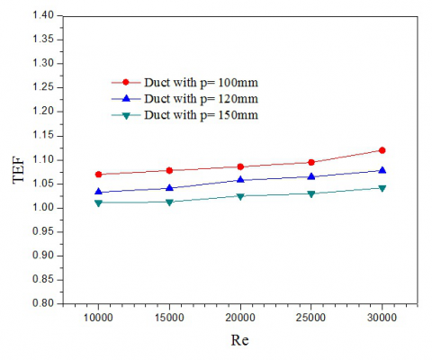
3.7 Effect of pitch (p)
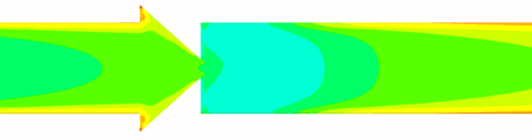
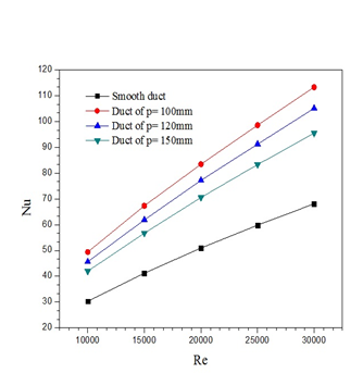
This section delas the effect of pitch dimension varied from 100 mm to 150 mm on heat transfer characteristics. The enhancement is presented in terms of Nusselt number, friction factor and thermal enhancement factor as shown in Fig 17(a), 17(b) and 17(c). Nusselt number is increased as Reynolds number increases because of higher turbulence intensity. After using turbulators at a different pitch, a significant increase in Nusselt number has been observed. This numerical result reveals that Nusselt number is increased with decreasing pitch. The lower value of pitch indicates a higher number of turbulators mounted on the walls. The increase in Nusselt number is found 1.388, 1.52 and 1.64 over the smooth duct for the ducts with turbulators mounted at a pitch of 150mm, 120mm and 100mmrespectively. In addition, the improvement is about 38.8%, 52%, and 64% respectively. This is due to higher number of turbulators at a lower pitch of the duct. For 100mm pitch, disturbance in the flow will be more and hence higher intensity vortices will be generated as shown in Fig 18(a), 18(b) and 18(c). Temperature contours for all the pitches are shown in Fig 19(a), 19(b) and 19(c). From these contours it is noted that the maximum temperature for pitch 100mm, 120mm and 150mm are 398.5K, 400.9K and 402.8K. So duct with turbulators at a pitch of 100mm will provide an excellent temperature gradient in the heated wall temperature.
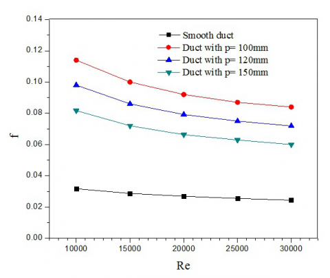
Darcy friction factor is calculated for all pitch values. It is noticeable that friction loss increases with a decrease in pitch values. The mean increase in friction factor for pitch 100mm, 120mm and 150mm are 3.47, 2.98 and 2.49 times over the smooth duct.
The best thermal enhancement factor has been obtained for 100mm pitch. At Reynolds number 30000, TEF value obtained for pitch 100mm, 120mm and 150mm are 1.042, 1.078 and 1.12 respectively.
Figure 17(a). Comparison of Nusselt number different pitch of turbulators
Figure 17(b). Comparison of friction factor different pitch of turbulators
Figure 17(c). Comparison of thermal enhancement factor different pitch of turbulators
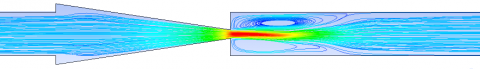
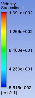
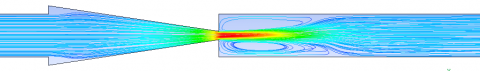
Figure 18(a). Velocity contour of duct for pitch 100mm at Re= 20000
Figure 18(b). Velocity contour of duct for pitch 120mm at Re= 20000
Figure 18(c). Velocity contour of duct for pitch 150mm at Re= 20000
Figure 19(a). Temperature contour of duct for pitch 100mm at Re= 20000
Figure 19(b). Temperature contour of duct for pitch 120mm at Re= 20000
Figure 19(c). Temperature contour of duct for pitch 150mm at Re= 20000
Three-dimensional numerical simulation is carried out to investigate the effect of geometric parameters on turbulent forced convective heat transfer and friction characteristics in a square duct roughened by wedge shaped rib and groove turbulators. The following conclusions have been drawn from the above analysis:
1) The effect of Reynolds number on heat transfer and friction loss is shown for all the calculations. The higher value of Reynolds number leads to enhance the turbulent intensity due to which heat transfer rate enhances.
2) The parallel arrangement of turbulators found to be more effective than staggered one in terms of heat transfer enhancement.
3) Both the Nusselt number and Darcy friction factor increases with increase in groove height because of thepresence of larger stagnation region. The highest enhancement factor (1.125) is found for groove height 2mm at Reynolds number 30000.
4) The effect of rib gap on theNusselt number and Darcy friction factor is directly associated with the blockage ratio. The thermal enhancement factor is found to be the best for rib gap of 4mm but anenhancement in Nusselt number and Darcy friction factor is found themaximum for rib gap of 2mm.
5) Both the Nusselt number and Darcy friction factor increases with increase in turbulator length because of generation of high-intensity eddies.
The decrease in pitch results in anincrease in both Nusselt number and Darcy friction factor as the surface area is increased.
First of all, I’d like to express my deep appreciation to my supervisor Dr.RajsekharPanua for his valuable guidance that greatly assisted the research of this paper. I also thank Mr. Manoj Kumar Triveni who provided insight and expertise during the course of research.
|
A |
Convective heat transfer area, m2 |
|
BR |
Blockage ration (e/H) |
|
b |
Groove height, m |
|
Dh |
Hydraulic diameter of square duct, m |
|
e |
Rib height, m |
|
f |
Darcy friction factor |
|
H |
Height of square duct, m |
|
h |
Convective heat transfer coefficient, W m-2K-1 |
|
k |
Turbulent kinetic energy |
|
ka |
Thermal conductivity of air, W m-1K-1 |
|
L |
Length of square duct, m |
|
L |
turbulator length, m |
|
Nu |
Nusselt number (hDh/ka) |
|
Pr |
Prandtl number (µCP/ka) |
|
p |
Pitch of turbulators, m |
|
Re |
Reynolds number (UDh/ν) |
|
Rg |
Rib gap, m |
|
T |
Temperature, K |
|
TEF |
Thermal enhancement factor |
|
ui |
Velocity component in xi direction, m s-1 |
|
U |
Mean velocity in duct, m s-1 |
|
Greek letter |
|
|
ϵ |
Dissipation of turbulent kinetic energy |
|
ρ |
Density of air, kg m-3 |
|
Г |
Thermal diffusivity, m2 s-1 |
|
τw |
Wall shear stress, N m-2 |
|
µ |
Dynamic viscosity, kg s-1 m-1 |
[1] Promvonge P., Thianpong C. (2008). Thermal performance assessment of turbulent channel flows over different shaped ribs, International Communications in Heat and Mass Transfer, Vol. 35, No. 10, pp. 1327-1334.
[2] Ramgadia A.G., Saha A.K. (2013). Three-dimensional numerical study of turbulent flow and heat transfer in a wavy-walled duct, International Journal of Heat and Mass Transfer, Vol. 67, pp. 98-117.
[3] Karthikeyan S., Elumalai N., Narasingamurthi K. (2015). Experimental study of developing turbulent flow and heat transfer in ribbed convergent/divergent rectangular ducts, Thermal Science, Vol. 19, No. 6, pp. 2219-2231.
[4] Wang L.B., Tao W.Q., Wang Q.W., Wong T.T. (2001). Experimental study of developing turbulent flow and heat transfer in ribbed convergent/divergent square ducts, International Journal of Heat and Fluid Flow, Vol. 22, No. 6, pp. 603-613.
[5] Promvonge P., Changcharoen W., Kwankaomeng S., Thianpong C. (2011). Numerical heat transfer study of turbulent square-duct flow through inline V-shaped discrete ribs, International Communications in Heat and Mass Transfer, Vol. 38, No. 10, pp. 1392-1399.
[6] Leung C.W., Chen S., Wong T.T., Probert S.D. (2000). Forced convection and pressure drop in a horizontal triangular-sectional duct with V-grooved (i.e. orthogonal to the mean flow) inner surfaces, Applied Energy, Vol. 66, No. 3, pp. 199-211.
[7] Eiamsa-ard S., Promvonge P. (2008). Numerical study on heat transfer of turbulent channel flow over periodic grooves, International Communications in Heat and Mass Transfer, Vol. 35, No. 7, pp. 844-852.
[8] Ahmed H.E., Ahmed M.I. (2015). Optimum thermal design of triangular, trapezoidal and rectangular grooved micro channel heat sinks, International Communications in Heat and Mass Transfer, Vol. 66, pp. 47-57.
[9] Xia G., Chai L., Wang H., Zhou M., Cui Z. (2011). Optimum thermal design of microchannel heat sink with triangular re-entrant cavities, Applied Thermal Engineering, Vol. 31, No. 6, pp. 1208-1219.
[10] Eiamsa-Ard S., Promvonge P. (2009). Thermal characteristics of turbulent rib-grooved channel flows, International Communications in Heat and Mass Transfer, Vol. 36, No. 7, pp. 705-711.
[11] Patil S.V., Vijaybabu P.V. (2012). Heat transfer enhancement through a square duct fitted with twisted tape inserts, Heat and Mass Transfer, No. 48, No. 10, pp. 1803-1811.
[12] Arslan K., Onur N. (2014). Experimental investigation of flow and heat transfer in rectangular cross-sectioned duct with baffles mounted on the bottom surface with different inclination angles, Heat and Mass Transfer, Vol. 50, No. 2, pp. 169-181.
[13] Eiamsa-Ard S., Promvonge P. (2009). Thermal characteristics of turbulent rib-grooved channel flows, International Communications in Heat and Mass Transfer, Vol. 36, No. 7, pp. 705-711.
[14] Promvonge P., Skullong S., Kwankaomeng S., Thiangpong C. (2012). Heat transfer in square duct fitted diagonally with angle-finned tape—Part 2: Numerical study, International Communications in Heat and Mass Transfer, Vol. 39, No. 5, pp. 625-633.
[15] Shui L., Gao J., Shi X., Liu J. (2013). Effect of duct aspect ratio on heat transfer and friction in steam-cooled ducts with 60 angled rib turbulators, Experimental Thermal and Fluid Science, Vol. 49, pp. 123-134.
[16] Leung C.W., Chan T.L., Chen S. (2001). Forced convection and friction in triangular duct with uniformly spaced square ribs on inner surfaces, Heat and mass transfer, Vol. 37, No. 1, pp. 19-25.
[17] Ahn S.W., Son K.P. (2002). An investigation on friction factors and heat transfer coefficients in a rectangular duct with surface roughness, KSME International Journal, Vol. 16, No. 4, pp. 549-556.
[18] Thianpong C., Chompookham T., Skullong S., Promvonge P. (2009). Thermal characterization of turbulent flow in a channel with isosceles triangular ribs, International Communications in Heat and Mass Transfer, Vol. 36, No. 7, pp. 712-717.
[19] Kwon H.G., Hwang S.D., Cho H.H. (2008). Flow and heat/mass transfer in a wavy duct with various corrugation angles in two dimensional flow regimes, Heat and Mass Transfer, Vol. 45, No. 2, pp. 157-165.
[20] Ramadhan A.A., Al Anii Y.T., Shareef A.J. (2013). Groove geometry effects on turbulent heat transfer and fluid flow, Heat and Mass Transfer, Vol. 49, No. 2, pp. 185-195.