OPEN ACCESS
The study by the CFD for a 3D natural convection in a tilted rectangular cavity filled by silicone oil at high Prandtl number has been compared to experimental results. A constant vertical temperature gradient has been performed by subjecting the horizontal walls to temperature Th and Tc; respectively. Other walls are adiabatic except the left small sidewall is differentially heating with temperature TA creating the horizontal temperature gradient. Different values of the lateral heating and the tilt with respect to the horizontal plane are imposed. The results draw dynamic maps. The influence of two factors (TA and ) on the flow pattern and on the convective heat transfer are analysed and discussed. The simulation flow pattern results are close to those obtained experimentally for treated cases with a minimum discrepancy between the both. A spectral analysis is done to show the fluctuations seen on the natural convective flow after the stability caused by the lateral heating and tilted angle; which based on the visualization of the amplitude as a function to the frequency. The results also show a significant impact on the flow fields and the heat transfer performance is improved.
CFD simulation, inclined vessel, heat transfer, natural convection, structure
Natural convection in horizontal and inclined enclosures has been extensively studied both experimentally and numerically, being of considerable interest in many engineering and science applications; e.g. electronic cooling, double-pane windows, heating and cooling of buildings, refrigerators, room ventilating, heat exchangers, solar collectors, environmental phenomena and so on. Several research are oriented toward the study of rectangular enclosures wherein the heat flow is typically unidirectional, i.e., the buoyancy is induced by imposing a heating either from the side or from below, as also performed in the general review works on natural convection in closed cavities by Stork et al [1] Ostrach [2], De Vahl Davis et al. [3], Khalifa Bdul-Jabbar [4] and Oztop et al [5].
A considerable work has been carried out considering more complex thermal and geometric boundary conditions. Elsherbiny [6] made an experimental study to investigate the natural convection heat transfer in inclined rectangular enclosures heated from above. They indicated that the lowest heat transfer is formed for j = 180°. Bairi et al. [7], performed a study on natural convection for high Rayleigh numbers using numerical and experimental techniques in rectangular inclined enclosures. They obtained a correlation between Nusselt and Rayleigh numbers and a minimal value for Nusselt numbers at j = 270°. While, Varol et al. [8], investigated the effects of inclination angle on natural convection in an enclosure with corner heater over a wide range of parameters; Rayleigh number; Prandtl number; dimensionless lengths of heater in x and y directions. Munir et al. [9], reported the fluid flow behavior and the characteristic of heat transfer from a differentially heated enclosure walls and tilted at various inclination angles using the double distribution function lattice Boltzmann numerical scheme with the same lattice structure. Further, Khezzar et al. [10], studied two-dimensional natural convection in fluid filled cavities heated from below with varied inclination angle numerically. A year later, Thamer Khalif Salem [11], conducted an experimental work to investigate the influence of inclination angle on natural heat transfer in a rectangular enclosure for three inclination angles; three mass flow rates and five heat fluxes. Aminossadati et al [12], investigated numerically the two-dimensional natural convective laminar flow in square enclosure at various angles of inclination with differentially heated opposite adjacent walls Their study shows different patterns of flow field and isothermal lines at high Rayleigh numbers, the average Nusselt number, maximum stream function and average temperature parameters behave differently at various inclination angles.
Another case existed during several years presented in the literature wherein the thermo-convective flows destabilize by a second temperature gradient. Shiralkar et al [13], investigated the flow and heat transfer in an enclosure subjected to comparable horizontal and vertical temperature differences, air-filled for Rayleigh numbers up to 106. Kirkpatrick et al [14], conducted heat transfer experimental measurements at high Rayleigh numbers in a water-filled, cubical enclosure. Corcione [15] performed a numerical investigation on the effect of various thermal conditions of sidewalls on flow-mode transition of natural convection in rectangular horizontal enclosures, heated from below and cooled on the top with different aspect ratios. Rayleigh numbers. Corcione’s results have shown that bidirectional differential heating has a significant effect on flow mode-transition of natural convection inside horizontal cavities. Zeroual et al [16, 17], explained experimentally the effect of the two temperature gradients on the flow inside a horizontal and tilt rectangular cavity. They raised a modification in roll pattern by the additional heat transfer presented by induced roll, where its distance varied in function to the temperature, tilt angle and thermal conductivity.
The main aim of this work is to present the effects of inclination angle and the second temperature gradient on flow field and heat transfer ratio also to compare the 3D numerical results with some experimental in paper [16,17].
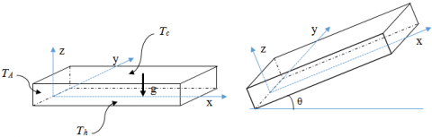
Consider a rectangular cavity of length L=10 cm, width l = 3 cm and height H =1 cm as shown in Figure 1, Filled with silicon oil 47v100 (Pr = 880 at 25°C and λ=0.16 W.m-1.K-1). The bottom and the top walls are maintained at temperature Th (27.6°C at z = 0) and Tc (21.1°C; 19.4°C at z = h), respectively. The remaining walls are adiabatic except the left small sidewall is maintained at temperature TA (variable). The gravitational acceleration acts in the negative z-direction and changes according to the inclination angle of the cavity.
Figure 1. Treated cavity
Transient, three dimensional laminar free convection flow of a viscous incompressible fluid, under the usual Bossinesq’s approximation, the governing dimensionless equations for conservation of mass, momentum and energy respectively are as follows[18]
$\frac{\partial u}{\partial x}+\frac{\partial v}{\partial y}+\frac{\partial w}{\partial z}=0$ (1)
$\frac{\partial u}{\partial t}+u \frac{\partial u}{\partial x}+v \frac{\partial u}{\partial y}+w \frac{\partial u}{\partial z}=-\frac{1}{\rho} \frac{\partial P}{\partial t}+\left(\frac{\partial^{2} u}{\partial x^{2}}+\frac{\partial^{2} u}{\partial y^{2}}+\frac{\partial^{2} u}{\partial z^{2}}\right)+\beta g\left(T-T_{0}\right) \cos \theta$ (2)
$\frac{\partial}{\partial t}+u \frac{\partial}{\partial t}+v \frac{\partial v}{\partial y}+w \frac{\partial v}{\partial z}=-\frac{1}{\rho} \frac{\partial P}{\partial y}+\left(\frac{\partial^{2} v}{\partial x^{2}}+\frac{\partial^{2} v}{\partial y^{2}}+\frac{\partial^{2} v}{\partial z^{2}}\right)$ (3)
$\frac{\partial w}{\partial t}+u \frac{\partial w}{\partial x}+v \frac{\partial w}{\partial y}+w \frac{\partial w}{\partial z}=-\frac{1}{\rho} \frac{\partial P}{\partial z}+\left(\frac{\partial^{2} w}{\partial x^{2}}+\frac{\partial^{2} w}{\partial y^{2}}+\frac{\partial^{2} w}{\partial z^{2}}\right)+\beta g\left(T-T_{0}\right) \sin \theta$ (4)
$\frac{\partial T}{\partial t}+u \frac{\partial T}{\partial x}+v \frac{\partial T}{\partial y}+w \frac{\partial T}{\partial z}=\frac{\lambda}{\rho C_{P}}\left(\frac{\partial^{2} T}{\partial x^{2}}+\frac{\partial^{2} T}{\partial y^{2}}+\frac{\partial^{2} T}{\partial z^{2}}\right)$ (5)
The boundary conditions for the system of equation (1- 5) are [15]:
u = v = w for all wall (6)
j = 0 at x = L, y = 0 and y = l (7)
Th = 27.6°C at z = 0 (8)
Tc = 21.1°C and 19.4°C at z = H (9)
TA = Variable at x = 0 (10)
Ra and Pr is the Rayleigh and the Prandtl numbers, relevant to the natural convective, respectively, defined as:
$P r=\frac{v}{\alpha}$ ,$R a=\frac{\beta g H^{3} \Delta T}{v \alpha}$ (11)
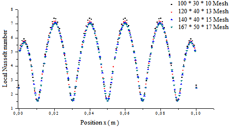
The simulations complement the experimental results, providing the thermal and dynamic maps of the fluid for the convective heat transfer. The preceding system of equations is resolved by the finite volume method described by Patankar [23] where the geometrical configuration is discretized by means of a structured grid of cells uniformly distributed in the domain. A uniform grid distribution in the three directions were generated for flow and thermal computations. The results were checked for grid independence (Figure. 2) and grid size change from 100 x 30 x 10 to 168 x 50 x 17 according to aspect ratio of the enclosure which has been created using Gambit 2.2.30 code.
Figure 2. Mesh independency
In this paper, we present the results using computational fluid dynamics code “FLUENT” (Fluent, ANSYS), with finite volume method to discretize the continuity, momentum and energy equations. This numerical method is wide used. Maria [19] is using this code for two 2-D models of a rectangular geometry at large different temperature. Triveni et al [20] examined the effect of different geometrical configuration of the base wall of a right triangular cavity on heat transfer rate using the commercial computational fluid dynamics code Fluent to analyse and simulate the model.
Under some conditions and approximations, FLUENT treats this kind of problem. For the steady-state cases, the operating pressure was defined, along with a hot-wall temperature. The standard discretization scheme in this code was used for pressure and the SIMPLE algorithm for the pressure / velocity coupling (Caretto and al. [21]; Fluent User’s Guide, 2005). A second order upwind scheme was used for the continuity, momentum and energy equations. The PRESTO! Discretization scheme was used for pressure. The under relaxation factors were set to 1 for pressure, density, body forces, 0.7 for momentum and 0.9 for energy. This helped to speed up the computations that were slowed down by the imposed conditions. The solutions were considered converged for steady-state solutions when the scaled residuals dropped below 10-3 for the continuity, momentum equations and 10-6 for the energy equation.
All results reported have been obtained for the case of cavity aspect ratio (Arx = 10 and Ary = 3), Pr = 880, DT = 6.5°C and 8.2°C, Tamb = 22.5°C and a constant value of Rayleigh (Ra = 6.26*103). The results are concerned the thermal and dynamic aspects. Taking into account the experimental test, which make it possible, on the one hand, to complement fields and on the other hand, the check of the agreement of both the numerical and experimental approaches.
4.1 Horizontal cavity
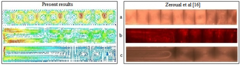
In the calculations, the initial field of velocity is considered null, and the initial temperature distribution between the hot and cold walls is linear. We notice in Figure 3 (a, b, c) that the fluid is rolling in the whole available domain; this allows a heat transfer by convection. Therefore, we observe for the velocity field ten transverse rolls parallel at the small side of the box (figure 3, a), where the adjacent rolls turn in the opposite direction. These numerical results are compared with experimental results [16].
Figure 3. Velocity fields for DT = 6.5°C.
a- TA = 0°C, b- TA = 42°C, c- TA = 59.6°C.
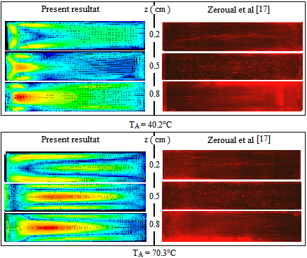
Figure 3, b and c: compare the numerical results obtained with the experimental ones, for various imposed temperatures in the left sidewall called lateral heating. The presence of the horizontal temperature gradient changes the pattern structurs as well shown in the two last (b and c). We noted two types of rolls; rolls with small sizes appear in odd number called Bénard rolls and a large one named the induced roll caused by the imposed temperature TA this last compress the others. For this case also, we can say that our resolution of the problem gave good results. It should also be noted that the influence of each gradient remains limited to a distinct portion of the total cavity, so the horizontal temperature gradient destabilized the classical convection and its influence is present by the induced roll, the distance of this last increases with the increasing of the side temperature. The simulation processes and experimental are agreement.
4.2 Tilted cavity
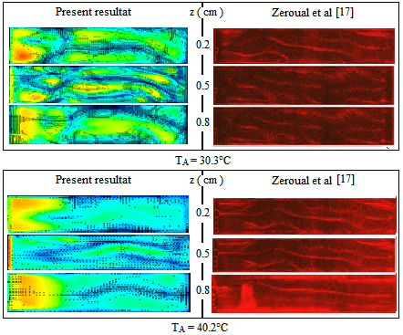
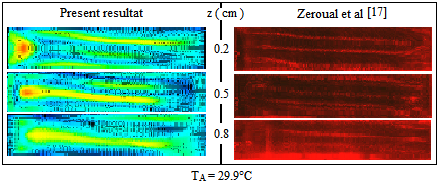
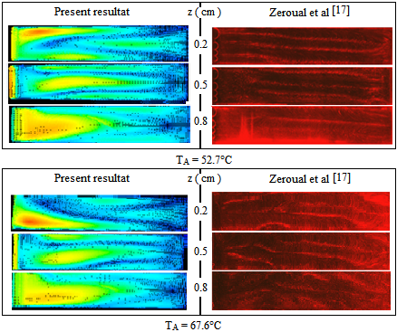
In this part, we compare a numerical study for the evolution structure when q varies to experimental ones [17], first without lateral heating after with it for special angle.
4.2.1 Tilt angle effect
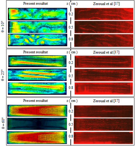
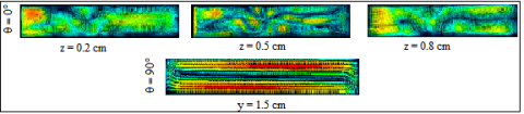
The lateral heating doesn’t applied for all angles. In this case, the convection is managed by the vertical temperature gradient caused by heating the bottom and cooling the top. Figures 4 (a, b, and c) compare numerical and experimental results for velocity maps in an inclined cavity for the angles 10°, 25° and 60° in three differents (xy) plane. The results present the effect of tilt angle on the fluid behaviour; it is clear from those results that there is a total disturbance at the transverse Rayleigh-Bénard rolls shown by 10 tubes perpendicular to the vertical temperature gradient and replace them with one, two or three longitudinal rolls.
Figure 4. Velocity fields with tilt for TA = 0°C.
Figure 5. Velocity fields with tilt.
For low inclinations (less than 10°), the structure is formed of a mixture transverse and longitudinal rollers and it can be considered as the transition from one network to another [17]. While for 90°, we find that the cavity becomes vertical and the convective structure observed in this case is produced by the flow as a single longitudinal roll on the lengthy side of the vessel. It is well illustrated numerically in Figure 5 for q = 5° and 90°.
4.2.2 Tilt angle and lateral heating effect
As already pointed out, the sidewall has an influence on the convective structure, this is a result of secondary flow near the walls where transverse rolls. This influence is well confirmed experimentally [17], where the increase of lateral heating TA causes the increase size of adjacent roll (Figure 3). Increasing lateral heating temperature TA with the presence of the tilt angle produce a second destabilization of convective flow, but for large angles q, it is far from having same influences found in classical convection case (for q = 0° or low angle).
The effect of tilt angle and the side heating is very clear on the convective structure from the experimental and numerical results. Figures below show that the presence of these two factors setback the longitudinal rolls to the adiabatic side. It is clear that several condition thermal, geometrical and physical impact on the natural convection in confined volumes. Figures 6, 7 and 8 show the behaviour of the flow in function to the two parameters (TA and q) for:
→ Angle 25°
Figure 6. Velocity fields in (xy ) plane.
→ Angle 60°
Figure 7. Velocity fields for (xy ) plane.
→ Angle 90°
Figure 8. Velocity fields for (xy ) plane.
In an analysis of heat transfer characteristics [22], the local and average heat transfer coefficient in terms of the local and average Nusselt number of the laminar sub-layer near the surface, which can be applied in this study, is determined by:
$N u=\frac{h x}{\lambda}$ (12)
$\overline{N u}=\frac{1}{S} \int N\left.u\right|_{w a l l} d S$ (13)
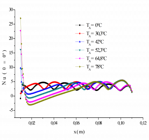
The variation of ''Nu'' as a function of lateral heating and inclination in the convective regime are displayed underneath for few experimental conditions. It can be seen that the number of "Nu" is different from the classical case of convection flows influenced by physical and geometric parameters (as our study case) as fluid behaviour in the cavities. In this study, the Nusselt number is presented by the average code Fluent (ANSYS) and plotted by the software Origin 8. These graphs present the effect of the both parameters on the convection flow.
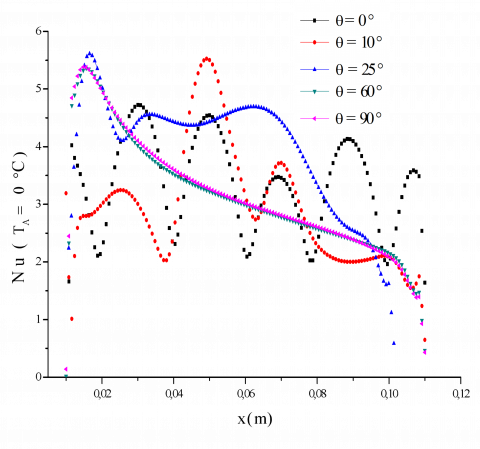
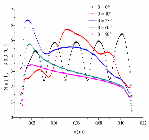
Figure 9. Local Nusselt number in horizontal and inclined cases on the bottom wall. a- q = 0°, Nu =f (TA), b- TA = 0°C, Nu =f (q), c- TA = 30.3°C, Nu = f (q).
Figure 9 shows the evolution of the local Nusselt number along the bottom wall for angles 0°; 10°; 25°; 60° and 90°. At first, for q = 0° with TA varies (Figure 9 a), it can be seen that the local Nusselt number has temporal oscillation (TA = 0°C). The distribution of local Nusselt number has lost its nearly regular periodic property near the lateral heating wall (TA > 0°C) [18].
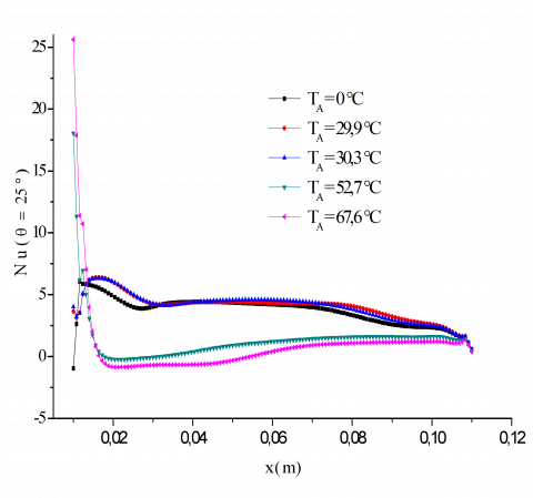
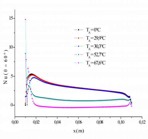
Figure 10. Local Nusselt number on the below wall for different TA. a- q = 25°, b- q = 60°, c- q = 90°.
Figure 9 b and c, Compares the local Nusselt number along the bottom wall for five different inclinations (q = 0°, 10°, 25°, 60° and 90°) with two lateral heating values (TA = 0°C, TA = 30.3°C). Can be distinguished by figures:
√ Local Nusselt number has lost the temporal oscillation for the four last angles.
√ For low angle (q = 10°), local Nusselt number increase in midst of bottom wall between 0.03 m to 0.07 m where we can see a pick and decrease in the side walls left (where we had applied the lateral heating and inclination angle) and right (where we had applied adiabatic limit condition).
√ For angles q ³ 25°, the local Nusselt number has a maximum and minimum near the left and right vertical sides, respectively.
Figures 10 (a, b, and c) represent the effect of lateral heating with the same inclination angle on the distribution of local Nusselt number along the bottom wall. The trend is almost linear for the highest inclination angle. The maximum heat transfer is obtained near the left vertical wall, for all values of TA. Fig. 10, c, there is a huge difference between inclination angle q = 90° and the two others, it is observed that the maximum and minimum values inverse their position along the bottom wall except for the value TA = 0°C.
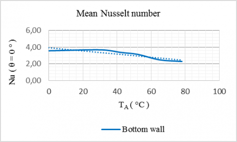
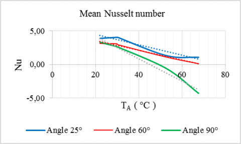
Figures 11 (a, b and c) summarize the overall heat transfer for both cases inclination and lateral heating. Figure 11. a: illustrates the effects of lateral heating on heat transfer. As can be seen from the figure, there is big influence of the lateral heating on the mean Nusselt number due to the increases value of TA; $\overline{N u}$ decreases and its well shown in biggest values of TA. Similarly, Figure 11, b indicates the variation of mean Nusselt number as a function of inclination angle for two lateral heating (TA = 0°C and TA = 30.3°C). As expected, the value of mean Nusselt number decrease for low inclination than it increases again for q = 25° and come back down again for the two higher last angles. Finally, the value of mean Nu number as a function of lateral heating TA and inclination angle $\theta$ is plotted in Figure 11, c the value of $\overline{N u}$ decreases with increasing value of the two parameters (TA and q).
Figure 11. Mean Nusselt number in bottom wall a- q = 0°, Nu =f (TA), b- TA = 0°C, 30.3°C, Nu =f (q), c- Nu = f (q, TA).
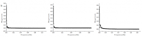
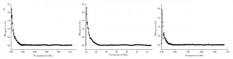
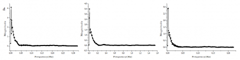
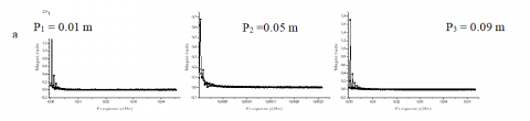
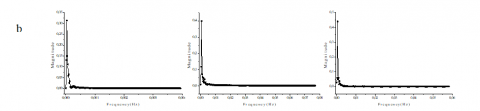
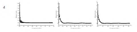
Spectral analysis is a mean to clarify the fluctuations imposed by the both variable factors: The lateral heating and the angle of inclination on the magnitude specifically of the natural convection as a function of the frequency. It is presented the stability of the problem treated by a magnitude in function to the frequency. In this study, the spectral analysis touches the visual form for stability of the natural convection plotted by Fluent FFT Plot. Despite that the stability of the phenomenon treated is achieved; this analysis type shows that the variation of one of the thermal and geometric parameters as the lateral heating and the angle of inclination effect on the representation of the system characteristic amplitude, which are well shown in figures below. This method based on the chosen of various points in the studied domain and plotted they are magnitude in function to the frequency; these points are located in the center according to y-axis, z-axis and varied along to x-axis (P1 = 0.01 m, P2 = 0.05 m and P3 = 0.09 m) for different lateral temperatures and angles.
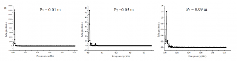
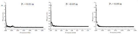
Figure 12. Spectral analysis for the middle point P2 = 0.05 m, a- q = 0°, b- q = 25°, c- q = 60°, d- q = 90°
Fig. 12, a, b, c and d present the analysis of the middle point (P2 = 0.05 m) in function to the tilted angle (0°, 25°, 60° and 90°). It is well noted that the tilted angle destabilized the amplitude of the convective system; expressed by small vibrations near to the original amplitude of the system, which is directly proportional to the angle. This vibrations amplitude increases with the angle and the number decreases. Fig. 13, 14 and 15 show the spectral analysis for three different angles in three points with four various lateral temperature TA. The presence of the two parameters clearly effect on the amplitude of the studied system by the presence of fluctuations.
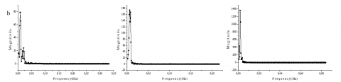
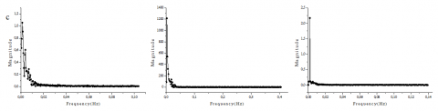
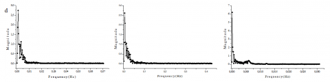
For the angle 25° Fig. 13, a, b, c and d); the fluctuations have an importance close to the active side wall therefore at point P1 = 0.01 m and the amplitude becomes small away from this point whatever the value of TA. While these fluctuations are concentrated and have a small amplitude without lateral heating for the angle q = 60° except the third point (Fig. 14, a), contains two important amplitudes. The application of the lateral heater effect on their concentration as well as their amplitude at all point (Fig. 14, b, c and d). Lateral heat is directly proportional to the amplitude of the fluctuation and inversely proportional to the concentration of their presence. Fig. 15, (a, b, c and d) illustrate that: as the angle q = 60° without lateral heating the angle q = 90° for TA = 0°C in the three points have the same configuration but with higher Magnitude. These fluctuations crushed at the beginning of the lateral heating for the low temperature but it shows again for the higher values.
Figure 13. Spectral analysis for angle q = 25°, a- TA= 0°C, b- TA= 30.3°C, c- TA= 52.7°C, d- TA= 67.6°C
Figure 14. Spectral analysis for angle q = 60°, a- TA= 0°C, b- TA= 30.3°C, c- TA= 52.7°C, d- TA= 67.6°C
Figure 15. Spectral analysis for angle q = 60°, a- TA= 0°C, b- TA= 30.3°C, c- TA= 52.7°C, d- TA= 67.6°C
It Natural convection in silicone-filled 3D rectangular enclosure tilted at an angle q (q = 0° to 90°) with respect to the vertical position was numerically simulated. The enclosure is heated and cooled from the two horizontal opposite walls while the remaining walls are adiabatic except the vertical small left sidewall. The computations were performed by CFD based on finite volume method. The dynamic measurement taken on the experimental bench confirm the results of CFD. The 3D model adopted makes it possible to establish Rayleigh-Bénard pattern. Though laws of this type obtained by different ways (experimental, numerical or both) are available in the literature, this work comes to complement these studies, in particular for high Prandtl numbers, which is of great interest for several engineering applications.
Attention is focussed on how the flow pattern and heat transfer rate are affected by the variation in both factors, heating lateral and inclination. It is found that increasing of TA and q beyond 0°C and 0° respectively destabilize the convective structure in the unsteady state for a certain value of the Rayleigh number. Complex behaviour was found near the heating lateral wall, the structure exhibits the induced roll for q = 0° with different TA and longitudinal patterns for q > 0° with accompanying increase and decrease in the heat transfer. The average Nusselt number reaches faster the steady-case when the angle is between 25° and 60°. The influence of these factors was observed in the variation of the mean Nusselt number throughout the cavity. More results using the spectral analysis are given; shows the version spectral of the specific magnitude for natural convection in a cavity as a function of the frequency. Which confirms the concept effect of the thermal and geometric parameters on the convective pattern by the fluctuations concentration near the active side.
|
Ar |
Aspect ratio |
|
CP |
Specific heat, J. kg-1. K-1 |
|
g |
Gravitational acceleration, m.s-2 |
|
H |
Cavity depth, m |
|
L |
Cavity length, m |
|
l |
Cavity width, m |
|
Nu |
Local Nusselt number |
|
$\overline{\mathrm{Nu}}$ |
Average Nusselt number |
|
P |
Pressure, Pa |
|
Pr |
Prandtl number |
|
Ra |
Rayleigh number |
|
S |
Surface, m |
|
T |
Temperature, °C; K |
|
u, v, w |
Velocity components, m.s-1 |
|
x, y, z |
Cartesians coordinates, m |
|
Greek symbols |
|
|
$\rho$ |
Density, Kg. m-3 |
|
$\theta$ |
Tilt angle, ° |
|
$\beta$ |
Thermal expansion coefficient, K-1 |
|
$\varphi$ |
Heat flow, W. m-2 |
|
$\lambda$ |
Thermal conductivity, W.m-1. K-1 |
|
α |
Thermal diffusivity, m2. s-1 |
|
$\Delta \mathrm{T}$ |
Difference of temperature, °C; K |
|
µ |
Dynamic viscosity, kg. m-1.s-1 |
|
υ |
Kinematic viscosity, m. s-1 |
|
Subscripts |
|
|
A |
Side lateral heating |
|
amb |
Ambient |
|
c |
Cold wall |
|
h |
Hot wall |
[1] Stork K., Muller U. (1972). Convection in boxes: Experiments, Fluid Mechanics, Vol. 54, No. 2. pp. 599 -611. DOI: 10.1017/S0022112072000898
[2] Ostrach S. (1988). Natural convection in enclosures, Heat Transfer ASME, Vol. 110, No. 4-b. pp. 1175-1190. DOI: 10.1115/1.3250619
[3] De Vahl Davis G., Jones I.P. (1983). Natural convection in a square cavity: A bench mark numerical solution. Int. J. Numer. Meth. Fluid, Vol. 3, pp. 227-248. DOI: 10.1002/fld.1650030305
[4] Khalifa Bdul-Jabbar N. (2001). Natural convective heat transfer coefficient - A review, II. Isolated vertical and horizontal surfaces, Energy Convers. Manage., Vol. 42, pp. 505-517. DOI: 10.1016/S0196-8904(00)00043-1
[5] Öztop H. F., Estellé P., Yan W. M., Al-Salem K., Orfi J., Mahian O. (2015). A brief review of natural convection in enclosures under localized heating with and without nanofluids, Int. Commun. Heat Mass Transf, Vol. 60, pp. 37-44. DOI: 10.1016/j.icheatmasstransfer.2014.11.001
[6] Elsherbing S.M. (1998). Free convection in inclined air layers, heated from above, Int. J. Heat Transfer, Vol. 39, No. 18, pp. 3925-3930. DOI: 10.1016/0017-9310(96)00047-6
[7] Bairi A., Laraqi N., Garcia de Maria J.M. (2007). Numerical and experimental study of natural convection in tilted parellelepipedic cavities for large Rayleigh numbers, Exp. Therm. Fluid Sci., Vol. 31, pp. 309-324. DOI: 10.1016/j.expthermflusci.2006.04.017
[8] Varol Y., Oztop H.F., Koca A., Ozgen F. (2009). Natural convection and fluid flow in inclined enclosure with a corner heater, Appl. Therm. Eng., Vol. 29, pp. 340-350. DOI: 10.1016/j.applthermaleng.2008.02.033
[9] Munir F.A., Sidik N.A.C., Ibrahim N.I.N. (2011). Numerical simulation of natural convection in an inclined square cavity, J. applied Sci., Vol. 11, No. 2. pp. 373-378. DOI: 10.3923/jas.2011.373.378
[10] Khazzer L., Siginer D., Vinogradov I. (2012). Natural convection of power law fluids in inclined cavities, Int. J. Thermal Sci., Vol. 53. pp. 8-17. DOI: 10.1016/j.ijthermalsci.2011.10.020
[11] Salem T.K. (2013). The influence of inclination angle on natural convection in a rectangular enclosure, Nat. Applied Sci., Vol. 4, No. 2, pp. 111-123.
[12] Aminossadati S. M., Ghasemi, B. (2005). The effects of orientation of an inclined enclosure on laminar natural convection, Int. J. Heat and Technology, Vol. 23, No. 2. pp. 43-49. DOI: 10.18280/ijht.230206
[13] Shiralkar G.S., Tien L. (1982). A numerical study of the effect of a vertical temperature difference imposed on a horizontal enclosure, Numer. Heat Transfer, Vol. 5, pp. 185-197. DOI: 10.1080/10407788208913442
[14] Kirkpatrick A.T., Bohn M. (1986). An experimental investigation of mixed cavity natural convection in the high Rayleigh number regime, Internat. J. Heat Mass Transfer, Vol. 29, pp. 69-82. DOI: 10.1016/0017-9310(86)90035-9
[15] Corcione M. (2003). Effects of the thermal boundary conditions at the sidewalls upon natural convection in rectangular enclosures heated from below and cooled from above, Int. J. Thermal Sciences, Vol. 42. No. 2. pp. 199-208. DOI: 10.1016/S1290-0729(02)00019-4
[16] Zeroual M., Cerisier P. (2000). The effect of walls conductivity on the convective structure in three heated walls vessel, World Renewable Energy Congress VI, Chapter 486. pp. 2249-2254. DOI: 10.1016/B978-008043865-8/50486-4
[17] Zeroual M., Cerisier P., Zereg M. (2007). Experimental study of Rayleigh-Bénard convection destabilized by heated side wall, Eng. Applied Sciences, Vol. 2, No. 6. pp. 1048-1053. DOI: jeasci.2007.1048.1053
[18] Varol Y., Hakan F., Oztop. (2008). A comparative numerical study on natural convection in inclined wavy and flat-plate solar collectors, Building and Envir. Vol. 43, pp. 1535-1544. DOI: 10.1016/j.buildenv.2007.09.002
[19] Maria A.K., Suleiman A.G. (2007). Buoyancy suppression in gases at high temperatures, Int. J. Heat and Fluid Flow, Vol. 28, No. 3. pp. 496 -511. DOI: 10.1016/j.ijheatfluidflow.2006.07.006
[20] Triveni M.K., Panua R. (2017). Numerical analysis of natural convection in a triangular cavity with different configurations of hot wall, Int. J. of Heat and Technology, Vol. 35, No. 1, pp. 11-18. DOI : 10.18280/ijht.350102
[21] Bairi A. (2008). Nusselt-Rayleigh correlations for design of industrial elements: Experimental and numerical investigation of natural convection in tilted square air filled enclosures, Energ. Convers. Manage, Vol. 49. No. 4. pp. 771-782. DOI: 10.1016/j.enconman.2007.07.030
[22] Caretto L.S., Gosman A.D., Patankar S.V., Spalding D. B. (1972). Two calculations procedures for steady, three-dimensional flows with recirculation, Proceedings of the Third International Conference on Numerical Methods in Fluid Mechanics, Springer-Verlag, Vol. 19. pp. 60-68. DOI: 10.1007/BFb0112677
[23] Patankar S.V. (1980). Numerical Heat Transfer and Fluid Flow, Hemisphere, Washington, D.C.