OPEN ACCESS
The present work is focused on the analysis of a SiC ceramic foam Volumetric Solar Receiver, a component of the solar tower technology. Using ceramic foams to achieve highly performing solar heat recovery systems is now a certainty. The convective heat transfer between the air and the ceramic foam plays an important role in the optimization of a volumetric air receiver. Also the macroscopic temperature distribution in the receiver is crucial to guarantee its safe and efficient operation. Heat transfer is investigated in a porous volumetric receiver, on which the concentrated solar radiation, coming from the heliostats field, impacts. A new simple two-equation model for the energy equation (Local Thermal Non Equilibrium assumption) is proposed. Governing equations are written with the Volume Averaging Technique (VAT). Numerical simulations are carried out through the commercial code COMSOL Multiphysics. Temperature fields and pressure drops inside the solar receiver, under different boundary and morphological conditions, are presented and discussed. The effect of process parameters on the receiver performance is highlighted.
Volumetric solar receiver, Ceramic foam, Numerical approach, Thermal analysis.
Energy is the engine of modern economy and increasingly essential for development and wellness, above all in a global world. Fossil fuels are still the primary source providing about 80% of total energy requirements; oil is, of course, the most important fossil fuel. During the past decade, its price greatly increased, thus leading a larger use of unconventional fossil fuels, such as gas and oil from schist, depleting natural resources, with irreversible damage to the environment.
Moreover the world population growth, the increasing CO2 emissions and the risk of a climate change have reinforced the idea that the use of fossil fuels should not last much longer. Thus it is necessary to concentrate efforts on the research of technologies that allow to exploit alternative energy resources and, particularly, renewable ones.
A recently improved technology is the concentrated solar power (CSP) [1], which, because of its high efficiency in energy conversion, is the best alternative to conventional fossil sources. However, CSP technology is applicable profitably only in areas with high values of annual solar radiation since it can exploit only its direct component.
The main component of the most common tower technology is the open volumetric receiver, consisting of a porous material heated by concentrated solar radiation. Fend et al. [2] carried out an experimental study to determine thermal conductivity and heat transfer properties of some selected porous materials. Additionally, they highlighted the potential efficiency of receiver prototypes made up by two materials in a laboratory scale. An experimental method of detecting unstable flow through porous media was developed. Most promising were materials based on ceramic foams and ceramic fabrics because of their potential towards large specific surface combined with beneficial pressure loss characteristics. It is important to notice that foams can be also used in other applications, such as heat exchangers [3].
Fend et al. [4] presented also a paper on two novel porous materials, foreseen as volumetric receivers of concentrated solar radiation: a double-layer silicon carbide foam and a screen-printed porous silicon carbide material. The experimental set-up was described and pressure loss and laboratory scale tests were reported. The authors compared the efficiency properties of the above said foam with those of commonly used materials, showing the better efficiency of the novel double-layer foam. Secondly, the direct typing process was employed to show the feasibility of manufacturing a porous ceramic structure with predefined permeability.
More recently, Bai [5] investigated analytically the thermal performance of a silicon carbide ceramic foam as solar air receiver, with reference to a one-dimensional physical model. The results of one-dimensional analysis of flow and heat transfer in ceramic foams suggest that there exists an input solar energy flux limit for an unpressurized system, which will lead to limit the power capacity and the outlet air temperature enhancement.
Wu et al. [6] analyzed the temperature distribution in the fluid and solid phases of volumetric solar air receivers. The pressure drop in the ceramic foams and the interfacial heat transfer between the fluid and the solid were taken into account by the model. The concentrated solar radiation absorbed by the ceramic foam and the radiation transport in the media were modeled with the P1 approximation. The temperature fields in the fluid and solid phases were obtained using the Local Thermal Non-Equilibrium model (LTNE). The comparison between the values predicted by the macroscopic model and experimental results showed that the macroscopic model could be used to predict the performance of solar air receivers. Sensitivity studies were carried out to analyze the effects of velocity, porosity, mean cell size and thermal conductivity of the solid on the temperature fields.
The same authors [7] studied numerically the convective heat transfer between the air flow and the ceramic foam in a volumetric air receiver. The local convective heat transfer coefficient inside the porous ceramic foam was evaluated. The geometry of the porous ceramic foam obtained starting from the Kelvin’s foam model was considered. A sensitivity study on the heat transfer coefficient was carried out with the porosity, velocity and mean cell size as parameters.
Sano et al. [8] investigated analytically the complex heat transfer in a silicon carbide ceramic receiver. Heat was transferred from the receiver solid phase to the air; the combined radiation, convection and conduction heat transfer within the receiver was investigated using a local thermal non-equilibrium model. The Rosseland approximation was made to account for the radiative heat transfer through the solar receiver, while the low Mach approximation was exploited to investigate the compressible flow through the receiver. The temperature of air and ceramic as well as the pressure along the flow direction were determined. Results showed that the pore diameter must be larger than its critical value, to achieve high receiver efficiency. The pore diameter that optimizes the receiver efficiency under the same pumping power was also found.
More recently, Kribus et al. [9] investigated the potential performance of volumetric absorbers as a function of geometry and material properties, to identify the best absorber design parameters and the expected highest efficiency. A simplified one-dimensional model was used to represent a planar slab of ceramic foam absorber, with local thermal non-equilibrium and effective volumetric properties. Three approaches for modeling the radiative transfer were considered, and the S4 discrete ordinates model was chosen, based on the validation against a detailed Monte-Carlo simulation. The boundary conditions were investigated in detail. Results indicated several guidelines to improve the absorber performance. Optimization of geometry (porosity and characteristic pore diameter) is insufficient to reach a high efficiency. A significant increase in convection heat transfer is required, beyond the normal behavior of ceramic foams. A reduction in the thermal conductivity of the absorber material is also needed to maintain the desired temperature distribution.
The novel double-layer ceramic foam holds great potential to enhance the efficiency. The effects of the geometry of each porous layer on the thermal performance of a foam are reported in [10]. The local thermal non-equilibrium model was adopted in energy equations of the fluid and solid phases. Radiative heat transfer in the foam, combined with the absorbed concentrated solar radiation, was solved with the modified P1 approximation. Results showed that the thickness of the first porous layer has a significant effect on the temperature field and pressure drop.
The present work is focused on the thermal analysis of a SiC ceramic foam Volumetric Solar Receiver, on which the concentrated solar radiation, coming from the heliostats field, impacts. A new simple two-equation model for the energy equation, under the Local Thermal Non Equilibrium assumption, is proposed. Governing equations are written with the Volume Averaging Technique (VAT) [11]. Radiation in the porous medium is modeled by using the Bouguer-Beer-Lambert equation. Numerical simulations are carried out through the commercial code COMSOL Multiphysics. Temperature fields and pressure drops inside the solar receiver, under different boundary and morphological conditions are presented and discussed. The effect of process parameters on the receiver performance is highlighted.
A sketch of the SiC foam porous receiver, together with boundary conditions, is presented in Fig. 1. The air and the concentrated solar radiation enter the absorber, where the heat is transferred from the solid matrix to the air. Due to its cylindrical symmetry, the receiver is described using a 2-D axisymmetric model, whose sizes have no remarkable effect on computations.
2.1 Governing equations
Due to the complexity of the geometry and of the boundary conditions, the porous medium is modeled as a single-phase equivalent medium. Volume-averaged governing mass, momentum and energy equations are employed. Since the local temperature difference between the two phases cannot be neglected, energy equations for solid and fluid phases are written with reference to a LTNE model. The flow is assumed to be steady and laminar, and effects of buoyancy, thermal dispersion and thermal tortuosity are neglected. The dependence on temperature of solid and fluid thermo physical properties is accounted for. Mass, momentum, and energy equations are
$\nabla \cdot\langle\boldsymbol{\rho} \mathbf{u}\rangle= 0$(1)
$\frac{\rho}{\varepsilon} \nabla \frac{\langle\mathbf{u}\rangle \cdot\langle\mathbf{u}\rangle}{\varepsilon}=-\nabla\langle p\rangle+\frac{\mu}{\varepsilon} \nabla^{2}\langle\mathbf{u}\rangle-\frac{\mu}{K}\langle\mathbf{u}\rangle-\frac{\rho f}{\sqrt{K}}|\langle\mathbf{u}\rangle|\langle\mathbf{u}\rangle$(2)
$\left(\rho C_{p}\right)_{f}\langle\mathbf{u}\rangle \cdot \nabla\left\langle T_{f}\right\rangle^{f}=\nabla \cdot\left(k_{e f f . f} \nabla\left\langle T_{f}\right\rangle^{f}\right)+h_{v}\left(\left\langle T_{s}\right\rangle^{s}-\left\langle T_{f}\right\rangle^{f}\right)$(3)
Figure 1. Sketch of the receiver with boundary conditions.
$0=\nabla \cdot\left(k_{e f f, s} \nabla\left\langle T_{s}\right\rangle^{s}\right)-h_{v}\left(\left\langle T_{s}\right\rangle^{s}-\left\langle T_{f}\right\rangle^{f}\right)+\nabla \cdot \mathbf{q}_{\mathrm{r}}$(4)
where $\rho$ is the density, u the inlet velocity vector, $\varepsilon$ the porosity, $\mu$ the hydraulic pressure, m the dynamic viscosity, K the permeability, f the inertial factor, Cp the heat capacity at constant pressure, keff,f the effective thermal conductivity of the fluid phase, T the temperature, hv the interfacial volumetric heat transfer coefficient, keff,s the effective thermal conductivity of the solid phase, and qr the radiative source term. The subscripts s and f refer to the solid and fluid phases, respectively, while the superscripts s and f refer to their intrinsic average values.
It is worth noticing that, upstream of the entrance section, an air fictitious domain is used to make numerical convergence easier. Mass, momentum and energy equations for a fluid with $\varepsilon$=1 and K→∞ are employed in the above region, whose sizes have no remarkable effect on computations.
2.2 Closing coefficients
In order to solve Eqs. (1 – 4), the closing coefficients K, f, keff,f, hv, keff,s and qr are required. In the momentum equation, the permeability, K, and the inertial coefficient, f, are [12]:
$K=\frac{d_{c}^{2}}{1039-1002 \varepsilon}$(5)
$f=\frac{0.5138 \varepsilon^{-5.739}}{d_{c}} \sqrt{K}$(6)
where dc is the cell size. For the energy equation, the effective thermal conductivities, keff,f, keff,s, interfacial volumetric heat transfer coefficient, hv, and the radiative source term ∇∙qr are required. The effective thermal conductivity, keff , is [13]:
$k_{e f f}=k_{e f f, s}+k_{e f f, f}=\frac{k_{s}(1-\varepsilon)}{3}+k_{f} \varepsilon$(7)
The volumetric heat transfer coefficient, hv, is obtained from the following correlation [6, 7]:
\(\begin{align} & {{h}_{v}}=\left( 32.50\text{ }{{\varepsilon }^{0.38}}-109.94\text{ }{{\varepsilon }^{1.38}}+166.65\text{ }{{\varepsilon }^{2.38}}- \right. \\ & \left. -\text{ }86.98\text{ }{{\varepsilon }^{3.38}} \right){{\operatorname{Re}}_{\text{c}}}^{0.438}{{\varepsilon }^{0.438}}\frac{{{k}_{f}}}{{{d}_{c}}^{2}} \\ \end{align}\)(8)
where Rec = |u| $\rho$ dc/$\mu$ is the cell Reynolds number. The radiative term ∇∙qr is modeled assuming that the radiation is collimated; thus the Bouguer-Beer-Lambert equation holds:
$\nabla \cdot \mathbf{q}_{\mathbf{r}}=\mathbf{n} \cdot \nabla I=\frac{d I(z)}{d z}=-\langle\beta\rangle I_{0} e^{-(\beta) z}$(9)
where I is the radiation intensity, I0 the concentrated solar radiation intensity, and β the extinction coefficient. It is important to observe that Eq. (9) can be obtained from the Radiative Transfer Equation (RTE), under the assumptions of no-inscattered energy and no-emitted energy. Using Eq. (9) makes the model simpler since three, rather than four, equations need to be solved. The concentrated solar radiation intensity is assumed to be equal to 600 kW/m2 [7]. It can be modeled by using a Gaussian distribution [14], but, for the sake of simplicity, in the simulations reference is made to the Gaussian mean value.
The extinction coefficient is taken from Viskanta [15]:
$\beta=\frac{3}{d_{c}}(1-\varepsilon)$(10)
2.3 Boundary conditions
Boundary conditions for Eqs. (1 – 4) are resumed in Fig. 1.
At the inlet section, the flow is assumed to be fully developed and a uniform temperature of the fluid phase is assumed, <Tf>f = 300 K. A Robin boundary condition is used for the solid temperature, to account for the radiative losses at the inlet section.
On the symmetry axis, a slip condition with no shear stresses is employed for the momentum equation. Temperature gradients along the normal direction are assumed to be zero for both fluid and solid energy equations.
On the lateral surface, a no-slip condition, together with a zero-gradient temperature boundary condition, is employed.
At the outlet section, it is assumed that the flow exits the porous domain at the atmospheric pressure, while an outflow condition is used for both fluid and solid temperatures.
Governing Eqs. (1 - 4) with boundary conditions are solved with a finite-element scheme by using the commercial code COMSOL Multiphysics. The grid is built up with both triangles and quadrilaters, with a total of about 15,000 elements. A convergence criterion of 10-4 is employed. Both grid independence and relative tolerance have been checked after remarking that smaller than 1% variations in the temperature profiles occurred for thicker grids.
Temperature fields and pressure drops inside the volumetric receiver have been evaluated and are presented in the following. The numerical analysis has been carried out for different values of porosity, inlet fluid velocity and cell diameter:
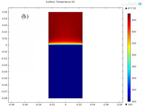
The temperature fields in the solid and fluid phases inside the receiver are reported in Fig.2. The working fluid is air; dc = 1.5 mm, $\varepsilon$= 0.80, |u| = 1.30 m/s. Figure 2a shows that, along the flow direction, the lowest temperatures in the solid are attained at the axis of the receiver, while their maximum values are reached at the computational domain confining walls. We can also notice a slight increase in the solid temperature along the flow direction, currently denoted as the volumetric effect. It occurs because the radiative contribution overcomes the convective contribution, namely the energy absorbed locally by the solid matrix is larger than the energy released to the fluid via interfacial convection. Figure 2b points out a marked increase in the fluid temperature in the proximity of the receiver entrance section, which disappears within a short downstream distance.
Figure 2. Temperature field (K) in the receiver, for dc = 1.5 mm, $\varepsilon$ = 0.80, |u| = 1.30 m/s: a) solid phase, b) fluid phase
The fluid and solid volume averaged temperatures as a function of the axial coordinate, predicted in the present study, for different values of the inlet velocity, the cell size, the porosity, together with numerical predictions by Wu et al. [6], are presented in Fig.3. It is worth remarking that Wu et al. [6] investigated the radiation using the RTE with a P1 four equation model. The simpler three equations model proposed in the present study slightly overestimates temperatures, since emitted and outscattered radiations are not accounted for. The figure shows that differences between temperatures predicted by the present model and by the Wu et al.’s model are less than 5%.
The radiation intensity as a function of the axial coordinate of the receiver, predicted in this study, for different cell sizes and porosities, is reported in Fig. 4. Figure 4a points out that the larger the cells size the higher the radiation intensity, because of the easier propagation of the radiation. In Fig.4b we can remark that the radiation intensity increases at increasing porosity, since again the propagation of radiation is made easier by the decreasing fraction of the solid volume.
The volume averaged temperatures of the fluid and solid and the pressure drop as a function of the axial coordinate in the receiver, predicted in the present study, for |u| = 1.30 m/s and different values of the cell size and the porosity, are reported in Fig.5. The figure shows that, whichever the cell size and the porosity, a same common value of the fluid and solid temperatures, called the equilibrium temperature, is attained. In a well performing volumetric receiver the so-called volumetric effect occurs, namely the temperature of the irradiated side of the absorber is lower than the temperature of the fluid leaving the absorber. The best performing volumetric receivers are that for dc = 1.0 mm in Fig.5a and that for $\varepsilon$ = 0.90 in Fig. 5b, respectively.
Figure 3. Fluid and solid volume averaged temperatures vs. axial coordinate: a) |u| = 1.51 m/s, $\varepsilon$ = 0.85, dc = 1.0 mm; b) |u| = 1.73 m/s, $\varepsilon$ = 0.80, dc = 1.5 mm
Figure 4. Radiation intensity vs. axial coordinate: a) $\varepsilon$ = 0.80 and different cell sizes; b) dc = 1.5 mm and different porosities
Figure 5. Fluid and solid volume averaged temperatures vs. axial coordinate, for |u| = 1.30 m/s: a) $\varepsilon$ = 0.80 and different cell sizes; b) dc = 1.5 mm and different porosities.
Figure 6. Volume averaged temperatures of the fluid and solid and pressure drop vs. the axial coordinate, for $\varepsilon$= 0.80, dc = 1.5 mm and different velocities.
The volume averaged temperatures of the fluid and solid and the pressure drop as a function of the axial coordinate in the receiver, predicted in the present study, for $\varepsilon$ = 0.80, dc = 1.5 mm and different velocities, are reported in Fig.6. Figure 6a shows that the lower the velocity and, consequently, the lower the mass flow rate, the higher the equilibrium temperature. We can also notice that radiation heat losses, <|q|s>= e \$sigma$ (<Ts>s4 - <T0>4), are larger in the inlet section.
Figure 7. Thermal equilibrium length for different configurations.
The thermal equilibrium length, Leq = z/L, for each investigated configuration, is reported in Fig.7. It is worth to be remarked that the larger the porosity and the cell size the longer thermal equilibrium length, whereas increasing the fluid velocity slightly increases the thermal equilibrium length. This depends on the contribution of the radiation heat transfer through the solid matrix and the interfacial convective heat transfer from the solid to the fluid. When the radiation contribution prevails over the local convection term the thermal equilibrium length becomes shorter, because of the increased volumetric effect. On the other hand, the slight increase in the thermal equilibrium length with the velocity is due to the increase in the convective heat transfer at the interface.
Figure 8. Volume averaged temperatures of the fluid and solid and pressure drop vs. the axial coordinate, for air and helium, $\varepsilon$= 0.90, dc = 1.5 mm, |u| = 1.30 m/s
Finally, the effect of working fluids other than air, namely carbon dioxide and helium, has been investigated. The volume averaged temperatures of the fluid and solid and the pressure drop as a function of the axial coordinate in the receiver, for $\varepsilon$ = 0.90, dc = 1.5 mm, |u| = 1.30 m/s, air and helium, are reported in Fig.8.
The receiver performs better when the fluid phase is helium rather than air. The same radiation heat losses and higher equilibrium temperatures are exhibited. This was to be expected, because of the higher thermal conductivity of helium than air. Differences between pressure drop in air and helium are almost negligible.
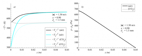
The volume averaged temperatures of the fluid and solid and the pressure drop as a function of the axial coordinate in the receiver, for $\varepsilon$ = 0.90, dc = 1.5 mm, |u| = 1.30 m/s, air and carbon dioxide, are presented in Fig.9.
Figure 9. Volume averaged temperatures of the fluid and solid and pressure drop vs. the axial coordinate, for air and carbon dioxide, $\varepsilon$= 0.90, dc = 1.5 mm, |u| = 1.30 m/s.
We can notice that with carbon dioxide temperatures are lower than those attained with air and the solid temperature in the proximity of the entrance section is lower than the equilibrium temperature, thus increasing radiation heat losses. This occurs since the volumetric heat transfer coefficient is lower than that with air, mainly because of the higher thermal conductivity of carbon dioxide. Furthermore, the carbon dioxide velocity is lower than that of air, since its larger density reduces advective motions that promote convective heat transfer. We can, therefore, conclude that the lower volumetric heat transfer coefficient and the lower velocity make the use of carbon dioxide not suitable in volumetric solar receivers.
Heat transfer and pressure drop in a volumetric solar air receiver made up by an open cell SiC foam have been numerically investigated using volume-averaged governing equations. A new simple two-equation model for the energy equation, under the Local Thermal Non Equilibrium assumption, has been proposed. The radiative heat transfer has been modeled with the Bouguer–Beer-Lambert law. Various foam morphologies and inlet velocities have been considered: $\varepsilon$ = 0.90, dc = 1.5 mm, |u| = 1.30 m/s.
The good agreement of results with literature data confirms that the Bouguer-Beer-Lambert law, instead of the Radiative Transfer Equation, can be used to account for the radiation in the model.
Larger porosities and smaller cell sizes enhance the volumetric receiver performance, while lower inlet velocities make the outlet air temperature higher.
The thermal equilibrium length, that is the distance from the foam inlet section necessary to attain the thermal equilibrium between the two phases, has been evaluated for the different configurations. Results showed that smaller porosities and cell sizes shorten the thermal equilibrium length, which, on the contrary, is only negligibly affected by the fluid inlet velocity.
Finally, the study of carbon dioxide and helium, instead of air, as working fluids showed that helium is a promising fluid, as to the heat transfer and pressure drop.
|
Cp |
heat capacity at constant pressure, J/kg K |
|
dc |
cell size, mm |
|
D |
receiver diameter, mm |
|
e |
emissivity |
|
f |
inertial factor |
|
hv |
volumetric heat transfer coefficient, W/m3 K |
|
I |
radiation intensity, W/m2 |
|
k |
thermal conductivity, W/m K |
|
K |
permeability, m2 |
|
L |
length, mm |
|
Leq |
thermal equilibrium length |
|
n |
normal vector |
|
p |
pressure, Pa |
|
q |
heat flux, W/m2 |
|
r, z |
cylindrical coordinates, mm |
|
Rec |
cell Reynolds number |
|
T |
temperature, K |
|
Greek symbols |
|
|
$\beta$ |
extinction coefficient, 1/m |
|
$\varepsilon$ |
porosity |
|
$\mu$ |
dynamic viscosity, Pa s |
|
$\rho$ |
density, kg/m3 |
|
$\sigma$ |
Stefan-Boltzmann constant, W/m2 K4 |
|
Subscripts |
|
|
0 |
reference |
|
eff |
effective |
|
f |
fluid |
|
i,j |
indexes |
|
r s |
radiative solid |
|
Superscripts |
|
|
f s |
fluid solid |
|
Others |
|
|
< > |
volume average |
[1] Rovense, F. Amelio, M., Ferraro, V. and Scormaienchi, N. M., “Analysis of a Concentrating Solar Power Tower Operating with a Closed Joule Brayton Cycle and Thermal Storage,” International Journal of Heat and Technology, vol. 34, no. 3, pp. 485-490, 2016.
[2] Fend, T., Hoffschmidt, B., Pitz-Paal, R., Reutter, O. and Rietbrock, P., “Porous materials as open volumetric solar receivers: Experimental determination of thermophysical and heat transfer properties,” Energy, vol. 29, pp. 823–833, 2004.
[3] Delavar, M. A. and Azimi, M., “Using porous material for heat transfer enhancement in heat exchanger: review,” International Journal of Heat and Technology, vol. 30, no. 2, pp. 93-96, 2012.
[4] Fend, T., Pitz-Paal, R., Reutter, O., Bauer, J. and Hoffschmidt, B., “Two novel high-porosity materials as volumetric receivers for concentrated solar radiation,” Sol. Energy Mat. & Sol. Cells, vol. 84, pp. 291–304, 2004.
[5] Bai, F., “One dimensional thermal analysis of silicon carbide ceramic foam used for solar air receiver,” Int. J. Therm. Sci., vol. 49, pp. 2400-2404, 2010.
[6] Wu, Z., Caliot, C., Flamant, G. and Wang, Z., “Coupled radiation and flow modeling in ceramic foam volumetric solar air receivers,” Sol. Energy, vol. 85, no. 9, pp. 2374-2385, 2011.
[7] Wu, Z., Caliot, C., Flamant, G., and Wang, Z., “Numerical simulation of convective heat transfer between air flow and ceramic foams to optimise volumetric solar air receiver performances,” Int. J. Heat Mass Tran., vol. 54, no. 7, pp. 1527-1537, 2011.
[8] Sano, Y., Iwase, S. and Nakayama, A., “A local thermal non-equilibrium analysis of silicon carbide ceramic foam as a solar volumetric receiver,” J. Sol. Energy Eng., vol. 134, paper number 021006, 2012.
[9] Kribus, A., Gray, Y., Grijnevich, M., Mittelman, G., Mey-Cloutier, S. and Caliot, C., “The promise and challenge of solar volumetric absorbers,” Sol. Energy, vol. 110, pp. 463–481, 2014.
[10] Chen, X., Xia, X. L., Meng, X. L. and Dong, X. H., “Thermal performance analysis on a volumetric solar receiver with double-layer ceramic foam,” Energy Conversion and Management, vol. 97, pp. 282–289, 2015.
[11] S. Whitaker, The Method of Volume Averaging, Springer Netherlands, Dordrecht, Netherlands, 1998.
[12] Wu, Z., Caliot, C., Bai, F., Flamant, G., Wang, Z., Zhang, J. and Tian, C., “Experimental and numerical studies of the pressure drop in ceramic foams for volumetric solar receiver applications,” Appl. Energ., vol. 87, no. 2, pp. 504-513, 2010.
[13] K. Kamiuto, “Modeling of composite heat transfer in open-cellular porous materials at high temperatures,” in Cellular and Porous Materials: Thermal Properties, Simulation and Prediction, A. Ochsner, G. E. Murch, and M. J. S. de Lemos, eds.; Wiley-VCH Verlag GmbH & Co., Weinheim, Germany, 2008, pp. 165-198.
[14] Aichmayer, L., Spelling, J. and Laumert, B., “Preliminary design and analysis of a novel solar receiver for a micro gas-turbine based solar dish system,” Sol. Energy, vol. 114, pp. 378-396, 2015.
[15] R. Viskanta, “Combustion and heat transfer in inert porous media,” in Handbook of Porous Media: Second Edition, K. Vafai, ed., CRC Press, Boca Raton, USA, 2005, pp. 607 -644.