OPEN ACCESS
CIRA manages the HYPROB Program, supported by the Italian Ministry of University and Research, with the aim of improving the national capabilities to develop rocket engines for future applications. A system line, named HYPROB-BREAD, focusing on LOX/LCH4 technology, is included. The final goal is the design and test of a regenerative LOX/LCH4 demonstrator. A step-by-step approach has been adopted to validate critical design aspects by simplified technological breadboards. The reliable operation of an engine is ensured by thermally efficient cooling jackets, which require the in-depth comprehension of the coolant behaviour. For this purpose, the MTP-BB has been tested. Another important issue is the evaluation of the thermal loads, transferred by the combustion hot gases to the thrust chamber walls. In this view, a Subscale Calorimetric Breadboard has been designed; 13 disks surround the chamber: they are fed up by water and provide the cooling and the measurement of the exchanged thermal power. The final article is a 3-ton-class LOX/LCH4 regenerative demonstrator, whose coolant is liquid methane, flowing in a cooling system, made by several axial channels.
This paper aims at describing the thermal investigations, conducted in the design and the verification phase for the aforementioned breadboards and demonstrator cooling jacket.
Design procedures, Liquid rocket engine, Numerical simulations, Thermal analyses, Thermal control.
The utilization of LOX/CH4 couple as a potential candidate to substitute hypergolic and solid propellants in the next future space propulsion systems has grabbed an increasing interest [1],[2]. The most advantageous reasons may be in the following:
Other important advantages are represented by the good throttle-ability, the possibility of multiple ignitions, the re-usability and the use of one of the available propellants, as coolant [8]. Due to these motivations, the HYPROB Program was conceived and financed by the Italian Ministry of University and Research and the technical and economic management was assigned to the Italian Aerospace Research Centre. The main objectives are to enable and improve the national system capabilities in the field of liquid rocket engines (LRE), with a specific focus on LOX/LCH4 technology [9]. The Program includes several lines: in particular, the system line, HYPROB-BREAD, has been foreseen in order to design, realize and test a LRE 30-kN-thrust demonstrator (DEMO), regeneratively cooled by using liquid methane. Some intermediate breadboards (Figure 1) have been designed and tested with the aim of analyzing some critical phenomena, like mixing and combustion processes of the propellants (gaseous methane and liquid oxygen) or the transcritical behaviour of methane [12]-[10].
Figure 1. Roadmap of the HYPROB-BREAD LOX/CH4 Demonstrator development
Test activities on MTP-BB (Methane Thermal Properties Breadboard), SSBB-HS (SubScale Heat Sink Breadboard) and the igniter article, together with the cold flow tests and material characterization, have been already successfully accomplished. In addition, the injection head has been recently manufactured and passed the first functional tests.
On the path for consolidating the DEMO design, data acquired by the testing of MTP represent a very important achievement. The activity resulted to be very significant for the description of the methane transcritical behavior (in a relevant environment and operative conditions) and for the study of important phenomena (like the thermal stratification inside a cooling channel and the deterioration of the coolant thermal performances). Moreover, the validation of the numerical procedures, adopted to verify the DEMO cooling jacket configurations [10] was another aim of the activity. Also the calorimetric version of the SSBB represents an important development step because it enables the investigation of oxygen-methane combustion issues at high pressures and the behaviour of off-nominal injectors. The Heat Sink version (SSBB-HS) has been already tested [12]; moreover, accurate information about the thermal power, released by combustion gases to the walls along the combustion chamber, is needed and will be collected in order to support the design phase, and validate the numerical procedures of the reactive simulations. Finally, the experience, on the manufacturing issues (on brazing processes) will be useful to fabricate the final demonstrator.
Figure 2. SSBB-HS during a firing test
The final demonstrator is represented by a regeneratively cooled ground engine. An assembly view is given in Figure 3, showing the most important parts like the igniter, the injector head, the combustion chamber and the cooling jacket.
Figure 3. Assembly of DEMO with main components
For the thrust chamber cooling system, a counter-flow strategy has been chosen: the refrigerant (CH4) enters the inlet fuel manifold (placed on the bottom of Figure 3) in liquid phase (at pressure and temperature, respectively, higher and lower than the critical values); then methane comes in the cooling jacket in the counter-flow direction with respect to the combustion gases. The propellant temperature raises, due to the energy released by combustion gases, and a phase “pseudo-change” occurs; then, methane comes in the fuel dome as a supercritical vapour and finally injected into the chamber through the injectors where mixes liquid oxygen [13]-[15] and burns. The cooling jacket is composed by rectangular-shaped channels, defined in the bottom part by a copper alloy liner, brazed on a close-out of Inconel©. Some details on the engine performances are shown by Table 1.
Table1. HYPROB DEMO main performance parameters
|
O/F |
3.4 |
PCC |
5.5 MPa |
|
Reaction efficiency |
0.98 |
Isp |
286s |
This paper aims at describing the thermal analyses, supporting the design and verification phases, regarding MTP-BB, SSBB-CC (calorimetric mode) and DEMO cooling jacket. For the MTP-BB, some details on the numerical simulations, conducted to rebuild the test campaign, are given.
Liquid rocket engines (LREs) have to sustain impressive thermal loads and mechanical stresses since combustion gas temperature (up to about 3600 K), and high pressure reign in the thrust chamber [2]. The operation of the modern LREs is enabled by the use of advanced cooling jackets. Their development is strictly connected with the study of the coolant behaviour. In fact, cryogenic coolants like methane typically shows a trans-critical behavior in the cooling systems during operation. However, in the case of methane data are still needed to accomplish the validation of engineering procedures and numerical codes [10] instead of other propellants, like hydrogen [11].
Figure 4. Typical cooling jacket configuration [16]
This is the main motivation, driving the design and the test of the first breadboard, named MTP Breadboard. In the HYPROB final demonstrator, the refrigerant is foreseen to be injected into the cooling system as a compressed liquid, with temperature and pressure values lower and higher than the critical ones (Tcr = 190.56 K and Pcr = 4.59 MPa), respectively. Combustion gases warm the fluid, which exits the cooling jacket as a supercritical gas [2]. For these reasons, the MTP working conditions include inlet pressure and temperature values ranging from 8.0 to 15.0 MPa and 130-140 K, respectively. In the MTP-BB methane is heated similarly to an engine since electrical cartridge system provide the thermal power to the breadboard channel. In this way, the fluid supercritical transition (pressure is higher than the critical value) from a liquid-like condition to a vapour-like one occurs without abrupt variations of thermo-physical properties, typical of sub-critical phase change phenomena.
2.1 MTP breadboard description
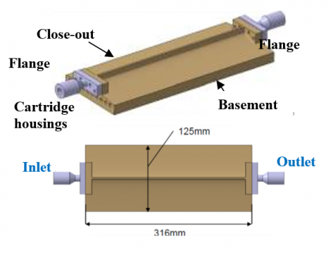
The Breadboard body is made of a copper alloy and ten slots have been realized in the basement to allocate the electrical cartridges, characterized by a maximum power of 12 kW. On the top, a rectangular narrow channel has been obtained by considering the typical dimensions of most thrusters’ cooling jackets, as shown by Figure 5. The total length (including flanges and fittings) is 316 mm while the width is 125 mm.
Figure 5. Sketch of MTP with some geometric details
Interfaces accommodate pressure and fluid temperature sensors while thermocouples were inserted in the basement along the breadboard axis and at different depth.
The following parameters were adopted to design the test-article and the maximum allowable temperature value was set to 800 K:
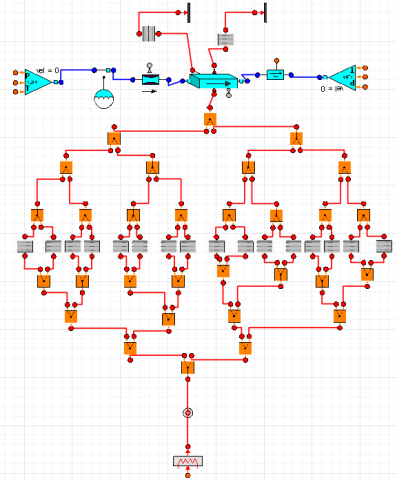
The preliminary design phase allowed to select a preliminary configuration and was accomplished by means of EcosimPro© tool [17]. Figure 6 shows the schematics, including the model of a rectangular channel, assumed to be uniformly heated by a power source on the bottom and insulated on the side and on the top. The channel was discretized by 16 nodes and a real gas model for methane was considered.
Figure 6. Ecosimpro© MTP model schematics view
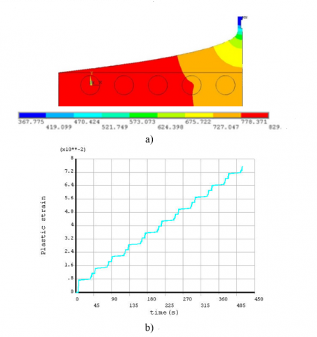
The chosen configuration was verified through a dedicated thermo-structural numerical campaign, accomplished by means of FE analyses (see Figure 7). According to the thermo-structural analyses, the test article is able to sustain 39 cycles, by considering a safety factor equal to 4. The test campaign was successfully performed at the Zucrow Laboratories of Purdue University, under the following conditions:
• mass flow rate = 15, 20, 25 g/s;
• exit pressure = 8.0, 10.0, 12.0, 15.0 MPa;
• impressed electrical power = 0 (cold flow), 12 kW;
• inlet fluid temperature = 130, 140 K.
Figure 7. Thermo-structural analyses: a) input temperature field; b) equivalent plastic strain accumulation
2.2 Numerical rebuilding activity of the test campaign
A rebuilding activity by numerical analyses has been started to deepen the comprehension of the methane behaviour. Another important aims was to collect information for the validation of the numerical models and engineering procedures, developed in the design phase of DEMO cooling jacket. Three-dimensional simulations were accomplished on significant test cases and a preliminary activity, regarding cold flow tests (useful to estimate the channel sand-grain roughness and to choose the turbulence model) was performed.
The numerical analyses were performed by means of ANSYS Fluent v14© [18]. The governing equations of continuity, momentum and energy in the three-dimensional formulation were solved under the hypothesis of steady state, real gas model [18] and turbulent flow. In addition, the conduction effects were considered and, after a trade-off analysis on the turbulence models, k-w sst was finally adopted. A pressure based method, a second-order upwind scheme and the SIMPLEC coupling one were chosen for energy and momentum equations and to couple pressure and velocity, respectively [18]. The convergence criteria of 10-6 and 10-10 for the residuals of the velocity components and energy were assumed, respectively. For the initialization, the inlet section conditions in terms of fluid temperature and pressure were set. An important issue was represented by the possibility to manage both the liquid phase and gas ones by implementing the NIST real gas model.
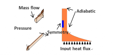
The breadboard is made of a copper alloy (depicted in orange in Figure 8) and its thermo-physical properties, evaluated through a specific characterization activity [13], were considered temperature-dependent. Because of the geometric and thermal symmetry, the numerical model contemplated only half channel in order to reduce the computational effort; the top and right surfaces of the breadboard were considered adiabatic while on the bottom wall a constant heat flux was applied. The adopted mesh was structured and characterized by about 2.7 million nodes.
Figure 8. Model sketch and applied boundary conditions
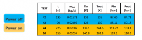
Results are here presented for two cold flow tests and two hot flow ones, experimentally investigated and rebuilt by means of CFD analyses. Table 2 reports some details on the considered test cases [14].
Table 2. Experimental test cases considered for the numerical rebuilding campaign
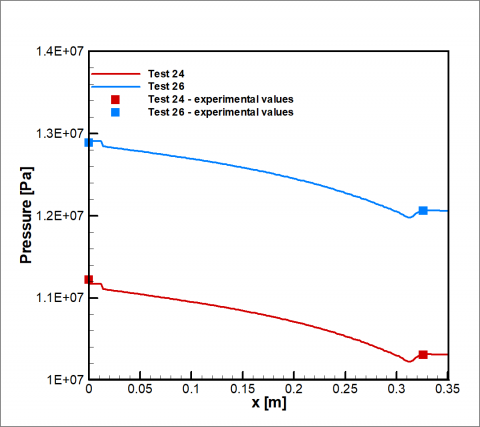
Figure 9 reports the pressure axial profiles for both the hot tests. First, it is important to underline that very low discrepancies are detected if results are compared to the experimental results (5.0% at maximum). Pressure decreases more than linearly in the last part of the channel because the fluid, entering the channel as a compressed liquid, undergoes a phase “pseudo-change” from a liquid-like condition to a vapour–like one at supercritical pressure values. As a result, density decreases and consequently velocity and pressure drops increase. The critical temperature and the pseudo-critical one are reached on average by the fluid at x/l = 0.38 and x/l = 0.72, respectively, as pointed by the fluid bulk temperature profiles of Figure 10.
The fields of temperature, specific heat and thermal conductivity for test 26, provided by Figure 11, allow the description of the transcritical behaviour of methane in a LRE cooling channel. First, a temperature stratification is observed: the fluid results to be hot in the bottom of the channel and near the left wall while temperature keeps significantly low on the top. Moreover, from x/l = 0.38 the fluid bulk temperature reaches the critical values: beyond this section a large part of the coolant starts to behave like a “gas” (near the hot walls) while remaining in “liquid” conditions on the top. After x/l = 0.72 bulk temperature equals the pseudo-critical temperature and the fluid behaves like a supercritical vapour. At this section, the highest values of specific heat are detected, in particular, in the middle part of the channel but also low values of thermal conductivity are observed, especially, near the hot wall. This condition leads to the deterioration of the fluid thermal performances [19]. However, in the present channel no overheating phenomena or abrupt temperature variations are detected, due to the high value of the wall roughness and high fluid pressure [19]. This information was useful for the design of the final demonstrator.
Figure 9. Numerical rebuilding (test 24 and 26): pressure axial profiles
Figure 10. Numerical rebuilding (test 26) – Fluid temperature and bottom wall temperature profiles
Figure 11. Numerical rebuilding (test 26) - Fields of fluid temperature, specific heat and thermal conductivity at five slices
The subscale calorimetric breadboard (SSBB-CC) has been designed to deepen the oxygen-methane combustion issues at high pressures, investigate the behaviour of different injectors and characterize the heat flux profile along the combustion chamber walls. The breadboard baseline concept is shown by Figure 12: a certain number of disks surround the chamber to allocate channels, fed up by water. Their role is dual: the cooling of the chamber and the measurement of the thermal load released from the combustion chamber to the walls by measuring the coolant flow rate and the temperature gain between the inlet and outlet sections. From Figure 12, it is also possible to note the injection head (on the left, depicted in light blue), where a single coaxial injector is allocated: it allows the injection of liquid oxygen and gaseous methane into the thrust chamber [22]. The SSBB has been designed to study combustion phenomena at the same chamber pressure of the final demonstrator (Pcc = 55 bar).
Figure 12. Sketch of the SSBB-CC breadboard and sketch of the model for disk design
3.1 Design procedure
The central point is represented by the thermal design of water disks. Their optimal arrangement in terms of number, dimension and channel geometries was identified through a dedicated tool. With reference to Figure 12, some constraints were considered:
a) the maximum coolant mass flow rate available from the test facility);
b) temperature of the channel wall (Tw) to avoid local boiling;
c) hot gas surface temperature (TH) less than 850K to preserve chamber material;
d) the minimum channel height (h), according to technology feasibility considerations [22];
e) minimum fluid ∆T between inlet and outlet sections to allow significant temperature measurements.
Figure 13 points out the flow chart of the design procedure, used for the selection of the configuration. The input heat flux (see Figure 14), due to the combustion inside the thrust chamber, was evaluated by dedicated reactive CFD analyses [23]. The design tool considered quasi-2D conduction effects and a Dittus-Boelter-derived correlation was adopted to perform the preliminary evaluation of convective heat transfer coefficients in the disk cooling channel. Two main parameters varied to perform the design loop, the solid/fluid filling percentage of the disk and their number (from 8 to 15). For each parameter, a configuration for the channels was obtained solving the following two equations for each disk [24]:
$q=\left(\frac{k}{t}\right)\left(T_{w h}-T_{w c}\right) A_{w e t}=h_{c}\left(T_{a w_{c}}-T_{w_{c}}\right) A_{e x c h a n g e}$(1)
$h_{c}=\frac{0.029 c_{p} \mu^{0.2}}{\operatorname{Pr}^{2 / 3}}\left(\frac{G^{0.8}}{d^{0.2}}\right)\left(\frac{T_{c o}}{T_{w c}}\right)^{0.55}$(2)
Figure 14. Input heat flux, evaluated by hot gas side analyses
The final goal of the procedure was the selection of a configuration, characterized by 13 disks (see Figure 15). For each disk, the height and the width of the channel, the thickness of the walls were identified, taking into account the manufacturing technological limits: ten disks cover the chamber cylindrical part, one disk the convergent and throat region, and the last two disks are placed in the nozzle.
Figure 15. Final arrangement: a) discretization of the thrust chamber wall; b) aspect ratio values of the disk channels
Different solutions were analyzed for the throat disk (disk 11), taking into account the difficulties into realizing a straight channel. They were characterized by almost the same hydraulic diameter and aspect ratio.
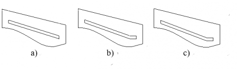
Figure 16 depicts the sketches of the initial solution and the final one. The initial solution (a) was very simple but eventually critical because the coolant fluid was too far from the material critical zones. The optimized arrangement (c) tried to move the coolant nearer the most critical part with respect to (b), without increasing the profile complexity. Figure 17 deals with the geometric sketch of the cooling channels, belonging to disks 1 to 10, 12 and 13.
Figure 16. Sketch of the cooling channel geometry in the throat region: a) initial configuration; b) intermediate configuration; c) final configuration
Figure 17. Sketch of the cooling channel geometry: a) cylindrical part; b) divergent zone
3.2 Design optimization and verification through numerical analyses
The CFD simulations were performed by means of Ansys FLUENT to thermally verify the adopted solutions and give support to the thermo-structural analyses [18]. A particular attention was focused on the throat disk, the most critical in terms of thermal stresses. In addition, the first disk, the fifth one, placed in the chamber region, and the twelfth one were considered. The governing equations in the three-dimensional formulation were solved under the hypotheses of steady state regime, incompressible and turbulent flow with temperature-dependent thermo-physical properties. The k-e turbulence model with standard wall functions was adopted after a trade-off analysis. The pressure based segregated method, a second-order upwind scheme and the SIMPLE coupling one were chosen to solve the governing equations. The convergence criteria of 10-6 and 10-9 for the residuals of the velocity components and energy were assumed. Fluid entered the cooling channel at P = 120 bar and Tin = 293 K.
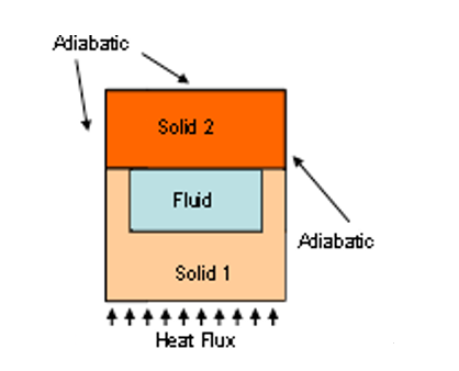
Figure 18 depicts the sketch of the model, considering a copper alloy as the liner material (solid 1) and Inconel© (solid 2) as the close-out part one.
Figure 18. Sketch of the cooling channel model, including materials and boundary conditions
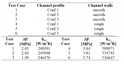
Simulations were performed both for the “simplified” models, regarding disk 5 (cylindrical zone), disk 11 (throat) and disk 12 (divergent zone), without the inlet and outlet manifold and for the “complete” configurations (see Figure 19). After a trade-off analysis on the throat disk, the third configuration of
Figure 16 was finally chosen because it ensured good thermal performances and relative low pressure drops. Table 3 summarizes the results in terms of pressure drops and average heat transfer coefficients.
Figure 19. CFD models: a) Throat disk, “simplified” model; b) Throat disk, “complete” model; c) cylindrical part disk, “complete” model; d) divergent part disk, “complete” model
Table 3. Test matrix of trade-off analysis on throat disk channel and main results
Figure 20 points out that the highest temperatures are detected for the channel bottom wall while the top wall is slightly affected by the input heat flux. The temperature fields show the most stressed zone in correspondence with the maximum value of heat flux. In the throat, the heat flux maximum value is equal to about 57 MW/m2 and the disk dissipates about 34 MW/m2 on average.
Figure 20. Throat Disk trade-off, temperature fields: a) chamber wall; b) bottom channel wall
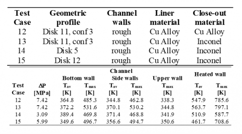
Far from the throat, temperature gradually decreases while for the upper surfaces temperature is very low. In addition, the selected configurations for disk 5 and 12 were object of CFD simulations, considering the simplified models. The highest temperature was detected for the channel bottom wall while the expected outlet fluid bulk temperature was about 296 K, 302 K and 299.5 K, for disks 1, 5 and 12, respectively. Pressure drops resulted to be very low, due to the larger channel cross-section. The heat transfer coefficients, evaluated on the bottom channel surface, attained values equal to about 144000 W/m2K, 148000 W/m2K and 199000 W/m2K for disk 1, disk 5 and disk 12.The configurations, selected through the design tool and verified by CFD analyses, were furtherly investigated by including the inlet and outlet manifolds. This pointed at evaluating the pressure drops for the whole system and temperature in the inlet and outlet regions, where a certain part of the chamber is not directly cooled by the refrigerant. Because of manufacturing reasons, a baffle divides the inlet and outlet sections, as reported by Figure 19, while the inlet and outlet cross-section dimension is that considered for the “simplified” analyses. Table 4 presents the main results, considering rough channel walls: the inlet and outlet manifolds led to a significant increase of pressure drops, due to the concentrated losses in the expansion and contraction areas and the inlet and outlet elbows. Moreover, a general increase of temperature was observed because in the baffle a part of the disk was not directly cooled by the refrigerant.
Table 4. Test matrix: complete disk models including inlet and outlet manifolds and main results
In the case of the throat disk, the maximum values are below 800 K and the most thermally stressed zone is located in a narrow region in the manifold zone. The presence of hot spots in the baffle influences also the temperature field of the manifolds, as depicted by Figure 21. Also for the other disks, temperature is far from the maximum allowable one.
Figure 21. Disk 11, complete model with rough channel walls: a) liner temperature distributions; b) slices of the liner.
The thermo-structural verifications were accomplished through FE simulations, starting from the aforementioned temperature fields and the imposed pressure conditions. 2-D transient simulations, considering the most stressed sections, were performed. The target of 6 firing tests was verified by these evaluations since the test article life-cycle was evaluated in about 12 firing tests (safety factor equal to 4).
Figure 22 describes the equivalent plastic strain distribution for disk 11 and 12. It is noted that the most stressed zones coincide with the most thermally loaded (see the disk on the left).
Figure 22. Thermo-structural simulations, disk 11 and disk 12: equivalent plastic strain field after ten cycles
The HYPROB DEMO is a thrust chamber, designed for the ground testing. It is regeneratively cooled and a counter-flow architecture has been considered, such as the coolant (LCH4) enters the cooling system as a liquid and moves in the counter-flow direction with respect to the combustion gases, as pointed out by Figure 23.
Figure 23. Scheme of a counter-flow architecture [25]
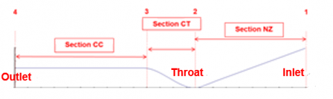
An in-house 1-D code was developed to design the cooling jacket and also 2-D corrections were considered [16],[24]. The design strategy contemplated to adopt a constant number of channels and a constant value for the rib width, w, while a variable value of the rib height, h, has been considered. In this way, an optimization of the cooling performances was achieved, taking into account some significant sections, highlighted by Figure 19, such as the nozzle (NZ), throat (CT) and cylindrical part (CC).
Figure 24. Sketch of the model including the sections considered for the optimization of the jacket cooling performances
The CFD verifications were accomplished by applying the same modelling, described in section 2.2. However, simulations were initialized at the cooling jacket inlet section conditions (Pin = 16.0 MPa and Tin = 110 K). The NIST real gas model was implemented in order to manage both liquid and gas phases. The considered solid materials were the following as also described by Figure 25: a copper alloy for the liner (solid 1), and Inconel for the close-out part (solid 2). The computational effort was reduced by considering half channel since its symmetry; the top wall and the side one were considered adiabatic while on the liner bottom wall a heat flux profile was applied, as depicted by Figure 25b. The final mesh distribution is a structured grid of about 1.6 million nodes and it has been generated by considering suggestions given by Fluent© user’s guide in the case of rough channel walls [18].
Figure 25. Cooling jacket simulations: a) model cross section, including materials and boundary conditions; B9 input heat flux profiles applied on the bottom surface
4.1 Results of numerical simulations (optimized configuration)
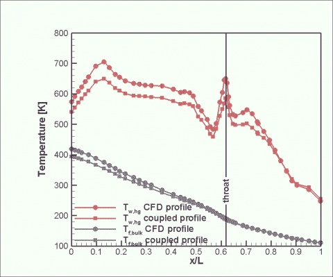
In the following, some results are presented to describe the obtained temperature profiles for the liner wall and fluid in the case of the optimized configuration. It is important to underline that the final configuration has exhibited a pressure drop of about 6.0 MPa, in line with the design requirements. If the “nominal” thermal load is considered for conservative purposes, the evaluated maximum values of temperature keep below the target of about 750 K. Thus, adopting the thermal coupling with thrust chamber, the wall temperature are expected to be further lower, as depicted by the axial profiles given in Figure 26. In fact, in the throat region a temperature value of about 610 K is detected while in the cylindrical part is about 660 K [26]. Moreover, pressure losses reduce of about 0.4 MPa.
Figure 26. Cooling jacket simulations: axial profiles of wall temperature for the liner (red lines) and fluid bulk temperature (blue lines)
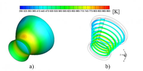
Figure 26 shows the fluid bulk temperature profile, which is useful to describe the behavior of the methane, flowing into the channel. In fact, the coolant is injected into the cooling systems in liquid phase but, as a result of the thermal power released by combustion hot gases, its temperature gradually increases moving towards the outlet section. Near the throat, temperature equals the critical temperature: from this section, the fluid tend to behave like a vapour near the hot walls of the channel, and like a “liquid” near the cold ones, especially in the top of the channel. However, in the cylindrical part, the fluid is completely composed by a supercritical vapour since, due to the high values of temperature and pressure. In Figure 27 the temperature field, including some details on walls and significant slices, allows to illustrate the gradual increase of the bulk temperature and the most stressed part of the channel domain, such as the liner part at the end of the cylindrical region of the chamber while the external and, especially, top walls are slightly affected.
Figure 27. Cooling jacket simulations: temperature field [K]
This paper describes the thermal and fluid-dynamics analyses, supporting the development of a liquid oxygen/ liquid methane rocket engine, in the framework of the Italian HYPROB Program. These analyses play a crucial role in order to deepen the comprehension of combustion processes at high pressure, support the thermo-structural analyses and optimize the design of the cooling system. However, the thermal analyses are important also for the design and the rebuilding activities of tests conducted on the several breadboards, conceived on the path of realizing the final test article. This product is represented by the HYPROB DEMO, a 30-kN-thrust engine, regeneratively cooled by the propellant. For example, the MTP Breadboard, in house designed and tested at Purdue University, allowed to deepen the comprehension of transcritical behaviour of methane, also by means of a specific numerical rebuilding campaign. The developed numerical procedure and the design guidelines were adopted for the final demonstrator. Moreover, another test article, called SSBB, has been designed to investigate combustion issues at high pressure, the heat release of the hot gases to the thrust chamber walls and the mixing phenomena. Numerical simulations supported the development of the cooling/measurement system and the thermos.-structural analyses, which established that the test article is able to withstand 6 firing tests of 30s at least, with a safety factor of 4. Finally, some results about the numerical analyses on the final configuration of the DEMO cooling jacket have been presented. The numerical investigations were performed to optimize the design, by highlighting the critical regions, according to the operational limits and requirements. Results were useful to perform 2-D FE simulations, aiming at evaluating the life cycle of the DEMO combustion chamber.
This work was performed in the framework of HYPROB Program, financed by the Italian Ministry of University and Research. The authors would like to thank our colleague, Vito Salvatore, whose efforts in the design phases were thoroughly appreciated.
|
A |
Exchange Area, m2 |
|
AR |
aspect ratio, - |
|
cp |
specific heat, J kg-1 K-1 |
|
d |
diameter, m |
|
h |
channel height of SSBB-CC and DEMO, m |
|
hc |
convective heat transfer coefficient, W m-2 K-1 |
|
L |
length, m |
|
P |
pressure, Pa |
|
Pr |
Prandtl number, - |
|
q |
input heat flux, W m-2 |
|
T |
temperature, K |
|
t |
wall thickness, m |
|
x, y, z |
spatial coordinates, m |
|
Greek ymbols |
|
|
$\lambda$ |
thermal conductivity, W m-1 K-1 |
|
$\mu$ |
viscosity, Pa s |
|
Subscripts |
|
|
cc |
combustion chamber |
|
cr |
critical |
|
in |
inlet |
|
pc |
pseudo-critical |
|
w |
wall |
[1] R. Schuff, “Integrated modeling and analysis for a LOX/Methane expander cycle engine: Focusing on regenerative cooling jacket design,” In Proc. 42nd AIAA/ASME/SAE/ASEE Joint Propulsion Conference & Exhibit, 9 - 12 July 2006, Sacramento, California, AIAA paper n.4534, 2006.
[2] C. D. Brown, “Conceptual investigations for a methane-fueled expander rocket engine,” In Proc. 40th AIAA/ASME/SAE/ASEE Joint Propulsion Conference and Exhibit, 11 - 14 July 2004, Fort Lauderdale, Florida, AIAA paper n. 4210, 2004.
[3] D. Haeseler, et al., “Green Propellant propulsion concepts for space transportation and technology development needs,” In Proc. 2nd International Conference on Green Propellants for Space Propulsion, 7-8 June, Cagliari, ESA SP-557, 2004.
[4] D. Haeseler, et al., “Recent developments for future launch vehicle LOX/HC rocket engines,” in Proc. 6th International Symposium Propulsion for Space Transportation of the XXIst Century, 13-17 May, Versailles, France, paper n. AAAF-02-100, 2002.
[5] N. Ierardo, F. Cuoco, A. Accettura, C. Congiunti and C. Bruno, “LOX-Methane systems for high thrust LRE,” in Proc. 4th International Conference on Launcher Technology, Liege, Belgium, 2002.
[6] S. Li, Y. D. Zhang, Y. Li and R. Q. Liao, “Equilibrium calculation and technological parameters optimization of natural gas liquefaction process with mixed refrigerant,” Int J Heat & Tech, vol. 33, no.2, pp. 12-128, 2015. DOI: 10.18280/ijht.330220.
[7] J. Collins, et al., “Sea-level flight demonstration & altitude characterization of a LO2/LCH4 based ascent propulsion lander,” In Proc. 45th AIAA/ASME/SAE/ASEE Joint Propulsion Conference & Exhibit, Joint Propulsion Conferences, AIAA Paper n. 2009-4948, 2009.
[8] M.E. Boysan, “Analysis of regenerative cooling in liquid propellant rocket engines,” Thesis, Middle East Technical University, 2008.
[9] V. Salvatore, et al., “Design and development of a LOX/LCH4 technology demonstrator,” in Proc. 48th AIAA/ASME Joint Propulsion Conference, Atlanta, USA, 2012.
[10] F. Battista, et al., “Experimental investigation of methane in transcritical conditions,” in Proc. 50th AIAA/ASME Joint Propulsion Conference, Cleveland, 2014.
[11] N. Oumrani, M. Aouissi, A. Bounif, B. Yssaad, F. Tabet H and I. Gokalp, “A first- and second-order turbulence models in hydrogen non-premixed flame,” Int J Heat & Tech, vol. 33, no.3, 2015. DOI: 10.18280/ijht.330304.
[12] F. Battista, et al., “Single-injector LOX/GCH4 combustion chambers manufacturing and experimental characterization in the framework of the HYPROB-BREAD Project,” in Proc. Space Propulsion, 2014.
[13] M. Ferraiuolo, et al., “Thermo-structural and thermo-fluid dynamics analyses supporting the design of the cooling system of a methane liquid rocket engine,” in Proc. 2014 ASME International Mechanical Engineering Congress, Montreal, 2014.
[14] D. Ricci, P. Natale and F. Battista, “Experimental and numerical investigation on the behaviour of methane in supercritical conditions,” Appl. Thermal Eng., vol. 107, pp. 1334–1353, 2016. DOI: 10.1016/j.applthermaleng.2016.07.052.
[15] M. Pizzarelli, F. Nasuti and M. Onofri, “Flow analysis of transcritical methane in rectangular cooling channels,” in Proc. 44th AIAA/ASME/SAE/ASEE Joint Propulsion Conference&Exhibit, 21-23 July, Hartford, 2008.
[16] G.P. Sutton and O. Biblarz, Rocket Propulsion Elements, John Wiley & Sons, 2010, ISBN-9780470080245.
[17] ECOSIMPRO User’s Guide, EA Internacional, Magallanes, Madrid, Spain.
[18] Ansys Fluent User’s Guide, v14.0, Ansys Inc., Canonsburg, PA, 2013.
[19] M. McLinden, et al., “NIST Standard Reference Database 23: REFPROP 7.0”, National Institute of Standard Technology, 2002.
[20] H. Negishi, Y. Daimon, N. Yamanishi and Y. Ohnishi, “Numerical investigation of supercritical coolant flow in liquid rocket engine,” in Proc. 46th AIAA/ASME Joint Propulsion Conference, Nashville, 2010.
[21] D. Ricci, P. Natale, F. Battista and V. Salvatore, “Experimental investigation on the transcritical behaviour of methane and numerical rebuilding activity in the frame of the HYPROB-BREAD Project”, In Proc. 2015 ASME International Mechanical Engineering Congress&Exposition Houston, USA, 2015
[22] D. Ricci, M. Ferraiuolo, F. Battista and V. Salvatore, “Thermal analyses supporting the design of the Hyprob sub-scale calorimetric breadboard,” In Proc. ASME-ATI-UIT 2015 Conference on Thermal Energy Systems: Production, Storage, Utilization and the Environment, 17 – 20 May, Naples, Italy 2015.
[23] P. Roncioni, et al., “CFD modelling and simulations of the HYPROB regenerative LOX/CH4 thrust chamber,” in Proc. 5th European Conference for Aeronautics and Space Sciences, July 1-3, Munich, Germany, 2013.
[24] D.K. Huzel and D. H. Huang, Modern Engineering for Design of Liquid-Propellant Rocket Engines. AIAA Book v.147, 1563470136, 1992.
[25] M. Rajagopal, “Numerical modeling of regenerative cooling system for large expansion ratio rocket engines”, J. Thermal Sci. Eng. Appl., vol 7, 011012, 2015. DOI: 10.1115/1.4028979.
[26] D. Ricci, F. Battista, M. Ferraiuolo, V. Salvatore and M. Fragiacomo, “Methane transcritical behavior in the cooling system of the HYPROB-BREAD LOX/LCH4 demonstrator rocket engine”, In Proc. 2015 ASME International Mechanical Engineering Congress&Exposition, Houston, USA, 2015.