OPEN ACCESS
Twisted tape is a widely used technique for heat transfer enhancement. In the present study, the influences of centre-trimmed twisted tapes (CTTT) on heat transfer rate, friction factor and thermal enhancement efficiency were numerically investigated. The centre-trimmed twisted tapes were used as swirl flow generators inside the circular duct. Investigations were performed in the Reynolds number range of 100 - 5,000 with four different centre-cleared twin twisted tapes at twist ratio (TR) of H/W = 1.0, 2.0, 3.0 and 4.0. The governing equations are solved with a finite-volume-based numerical method. A three-dimensional non uniform grid was generated, in order to critically examine the flow and heat transfer. Results show that the centre-cleared twin twisted tape causes considerable enhancement of heat transfer when compared with plain twisted tape (TT). The enhancement over standard twisted tape increases with the increase of Reynolds number. The improved parameter is observed in the range of Reynolds number below 800 and also above Re 4000 for all TR, though the best performance is found at TR = 1.0 and 3.0
Swirl flow, Centre-trimmed, twisted tape, friction factor, Thermal enhancement efficiency.
Heat is a form of energy which is transferred whenever there is difference in the temperature between a system and its surrounding. The research on heat transfer has been receiving important attention since long time ago, and has found applications in several areas such as cooling of electronic devices, manufacturing systems and solar energy system.
For long years, research works on twisted tape used for heat transfer augmentation have been done. Mixing of central region and wall region fluid are promoted in a heat exchanger consist of twisted tape. Swirl flow device is one of the important devices for passive augmentation techniques. Twisted-tape is one of them. Low heat transfer co-efficient in tube-side transitional flow of viscous liquid is encountered in many tubular heat exchangers are very useful in chemical process industry. The overall heat transfer coefficient is controlled by the low heat transfer coefficient of transitional flow in the tube-side. Thus enhancements of inside heat transfer coefficient result in increasing the overall performance of a heat exchanger. Several passive and active techniques that are available for augmentation of laminar flow heat transfer have been discussed in detail by Bergles and Webb [1], Bergles et al. [2, 3]. Using twisted tapes is one of the useful way to augment laminar flow heat transfer since the augmentation in heat transfer has been found to be much more than the corresponding increase in pumping power.
Heat transfer increments techniques play an important role here since heat transfer coefficients are normally low for transitional flow in plain tubes. Insertion of centre trimmed twisted tapes as shown in Figure. 1 in tube is one such augmentation technique. Tape inserts are cheap; they can be easily inserted to improve the thermal efficiency of the existing systems.
Also, for a known heat load, smaller heat exchangers can be manufactured, thereby reducing initial investments. Using of twisted tapes reduce the dominant thermal resistance of the viscous stream and reduce the required heat transfer surface area. However, the thermal efficiency improvements are accompanied by increased pressure drop. Twisted-Tapes are inserted in the circular duct leaving some gaps along the periphery and the corners of the duct cross-section. Full-length twisted-tape inside a circular duct increases the duct side surface heat transfer co-efficient of a heat exchanger.
Figure 1. Circular duct having full-length twisted-tape with centre trimmed and enlarged cross-sectional view
The rib height and rib pitch influence the heat transfer and friction characteristics. Integral rib-roughness has been used for the increasing the tube-side heat transfer coefficient in low-flow automotive radiators. Farrel et al. [4] tested one fully-ribbed and two broken ribbed flat radiator tube. They calculated friction factors for 200< Re <11, 000. However, the heat transfer coefficients were obtained only for turbulent flow with Re > 2000. The broken-ribbed tube with the maximum e/Dh yielded the highest heat transfer coefficient as well as the highest friction factor. Olsson and Sunden [5, 6] investigated the effect of rib arrangements for different geometrical tubes. Tubes are being compared by seeing the flow area and the volume goodness factor. The rib-roughened tubes showed the best performance than the base case. Saha and Dutta [7] have observed that, for regularly spaced twisted-tape elements, the thermohydraulic performance of twisted tapes with multiple twists in the tape module is not so different from that with single twist in the tape module. Twisted tapes uniform-pitch counterparts perform better than gradually decreasing pitch. Patil [8] researched with varying width twisted-tape inserts with both friction factor and Nusselt number is lower than those with full-width twisted tapes. Saha et al. [9,10] have implemented regularly spaced twisted-tape elements which are much better than full-length twisted tapes under certain circumstances. Li et al. [11] have introduced an optimal multi-layer spacer with non-woven nets in the outer layers and twisted tapes in the middle layer. Helical screw-tape inserts [12] behave the same way as the twisted tapes. Twin and triple twisted tapes [13] are also good enhancement devices. Dewan et al. [14] have reviewed the studies on twisted tapes. Hong et al. [15] have employed evenly spaced twisted tapes in a convergent–divergent tube. Jagged twisted tapes perform better than the classical twisted tapes [16]. Bhattacharyya et al. [17, 18] and Saha et al. [19] have recorded that the centre-cleared twisted tapes in combination with rib roughness perform quite better than the one to one augmentation technique acting alone for laminar flow through a circular duct up to a certain amount of twisted-tape centre- clearance.
It has been noted from the literature review that the centre-trimmed twisted tapes inserts has not been researched in the earlier years. The flowing of the fluid due to centre-trimmed twisted tapes generated swirl flow is likely to provide better mixing in the flow resulting in increased heat and momentum diffusion. This may increase heat transfer even if it may also give increased pressure drop. In this work, therefore, numerical heat transfer and pressure drop results of full-length centre-trimmed twisted tapes inserts in circular ducts are talked about.
2.1 Model
This work investigate transport phenomenon in centre-trimmed twisted tape tube . The range of Reynolds number is 100 - 5,000 and four different twist ratio (TR) 1.0, 2.0, 3.0 and 4.0. twisted tapes with centre-trimmed, with thickness of 0.001 m are fitted in the duct. Air (Pr 0.7) has been used as a working fluid.
2.2 Governing equations
The normalised form of continuity, momentum and energy equations for a three dimensional, steady state, incompressible flow and laminar forced convection heat transfer without viscous dissipation are given below. Although Reynolds number is greater than 2100, but laminar regime is assumed for simplicity.
Continuity equation:
$\frac{\partial u}{\partial x}+\frac{\partial v}{\partial y}+\frac{\partial w}{\partial z}=0$(1)
Momentum equations:
$\rho\left(u \frac{\partial u}{\partial x}+v \frac{\partial u}{\partial x}+w \frac{\partial u}{\partial x}\right)=-\frac{\partial p}{\partial x}+\mu\left(\frac{\partial^{2} u}{\partial x^{2}}+\frac{\partial^{2} u}{\partial y^{2}}+\frac{\partial^{2} u}{\partial z^{2}}\right)$(2)
$\rho\left(u \frac{\partial v}{\partial y}+v \frac{\partial v}{\partial y}+w \frac{\partial v}{\partial y}\right)=-\frac{\partial p}{\partial y}+\mu\left(\frac{\partial^{2} v}{\partial x^{2}}+\frac{\partial^{2} v}{\partial y^{2}}+\frac{\partial^{2} v}{\partial z^{2}}\right)$(3)
$\rho\left(u \frac{\partial w}{\partial z}+v \frac{\partial w}{\partial z}+w \frac{\partial w}{\partial z}\right)=-\frac{\partial p}{\partial z}+\mu\left(\frac{\partial^{2} w}{\partial x^{2}}+\frac{\partial^{2} w}{\partial y^{2}}+\frac{\partial^{2} w}{\partial z^{2}}\right)$(4)
Energy Equation:
$\left[u \frac{\partial T}{\partial x}+v \frac{\partial T}{\partial y}+w \frac{\partial T}{\partial z}\right]=\alpha\left[\frac{\partial^{2} T}{\partial x^{2}}+\frac{\partial^{2} T}{\partial y^{2}}+\frac{\partial^{2} T}{\partial z^{2}}\right]$(5)
Structured mesh was devoloped with very fine mesh, to get accurate results with less number of nodes. Different sizes of grids were tested as part of grid independence study. After a entire grid independence check, a mesh consisting of 415,951 cells were used for the current computation. The length of the tube is 2000 mm and the inner diameter of the tube is 20 mm, which are fixed in this research. The fluid entering the duct at a temperature of 300 K and wall temperature is at 500 K through the experiment.
Three dimensional governing equations shown above are discretized on a non-uniform structured grid using finite volume method. The pressures were calculated using semi implicit pressure linked equations (SIMPLE) scheme. With twist, a swirling flow will be generated and with changing the twist ratio, the number and intensity of these swirling flows will changed with the flow direction. The width of the twisted-tapes of the present study is 15 mm. The twist ratios (TR), H/W= 1.0, 2.0, 3.0 and 4.0 (H is twist length, and W is the wide of tape, as shown in Figure. 2) are tested along with a plain twisted tape of twist ratio 3.0. The discretized equations are then linearized using an processe called implicit technique and solved using third order accurate QUICK scheme. The convergence criteria for continuity, energy and momentum are 10-7 and 10-4, 10-5, respectively.
Figure 2. Layout of a circular duct containing a full-length twisted-tape
The Reynolds number of air flow in the duct is calculated from,
$R e=\frac{v D_{h}}{v}=\frac{\rho v D_{h}}{\mu}$(6)
Steady state values of the air and plate temperatures (constant wall temperature) in the various locationat the were used to determine the values of useful parameters, mainly heat supplied to the air “Qu” and heat transfer coefficient “h” calculated as:
$\mathrm{Q}_{\mathrm{L}}=\mathrm{m} \mathrm{C}_{\mathrm{p}}\left(\mathrm{T}_{\mathrm{a} \mathrm{o}}-\mathrm{T}_{\mathrm{ai}}\right)$(7)
$h=\frac{Q_{u}}{A_{p}\left(T p^{-T_{f}}\right)}$(8)
The convective heat transfer coefficient is then used to obtain Nusselt number, Nu, as,
$N u=\frac{h D_{h}}{K}$(9)
The friction factor is determined from the measured values of pressure drop (∆P), across duct length.
$f=\frac{2 \Delta P D_{h}}{4 \rho L V^{2}}$ or $f=\frac{2 \Delta P D_{h}}{4 L G^{2}}$(10)
To calculate the effect of heat transfer enhancement under given pumping power, the performance evaluation criteria Fan et al. [20] is employed as
$\eta=\left(\frac{N u}{N u_{0}}\right) /\left(\frac{f}{f_{0}}\right)^{0.33}$(11)
where Nu and Nu0 are Nusselt numbers for the enhanced tube and the smooth tube respectively, f and f0 are friction coefficients for enhanced tube and smooth tube respectively.
The results of, friction factor, thermal performance factor, heat transfer characteristics in the tube with centre-trimmed twisted tape (CTTT) and plain twisted tape (TT), under the transitional flow are shown in the present work. The effect of ratio for twist (H/W) on the thermohydraulic performance is also presented.
(a)
(b)
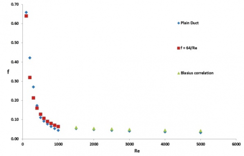
Figure 3. Comparison of the numerical results with the correlation data of the Nusselt number (Nu) and the friction factor (f) of the plain tube: (a) Nu, (b) f.
To validate the computational values of, the Nusselt number (Nu) and the friction factor (f) of the plain duct are compared with the proposed correlation under fully developed condition. From Figure 3 it is clearly observed that the nonconformity among the computational results and the correlation data is very narrow. Therefore, the present computational predictions have reasonable correctness.
Correlation proposed by Churchill and Ozoe [21] for laminar flow is,
$N u=4.364\left[1+(G Z / 29.6)^{\frac{1}{6}}\left\{1+\left[\frac{\frac{G z}{19.04}}{\left[1+\left((P r / 0.0207)^{2 / 3}\right]^{\frac{1}{2}} \times\left[1+(G z / 29.6)^{2}\right]^{\frac{1}{3}}\right.}\right]^{\frac{3}{2}}\right\}^{1 / 3}\right.$(12)
$\mathrm{f}=64 / \mathrm{Re}$(13)
Dittus and Boelter correlation [21],
$N u=0.023 R e^{0.8} P r^{0.4}$(14)
Blasius correlation [21],
$f=0.448 R e^{-0.275}$(15)
(a)
(b)
Figure 4 (a). Variation of Nusselt number with Reynolds number of twisted tape for different twist ratio, (b) Variation of friction factor with Reynolds number of twisted tape for different twist ratio
The variation o Nusselt number along with Reynolds number for different plain twisted tape (TT) with different twist ratio is shown in Figure 4(a). One can see form the Figure 4(a), that for each Re, the Nusselt number increase as the Reynolds number increases. It is also noted that Nu increase when twist ratio is small (TR 1.0). So, the small twist ratio shows some promising heat transfer augmented than the other tested twist ratio over the total range of Reynolds. From Figure 4(b) it is seen that the friction factor decreases with the increase of Reynolds number. The frictions factors correspond with twisted tape were higher than those of the plain duct. This is due to swirl flow, secondary flow and recirculation; turbulence intensity and drag forces produced by the twist in the duct. Also, one can see that the twisted tape with small twist ratio has the maximum friction penalty.
The performance of the heat transfer of CTTT is presented in the form of Nusselt number. Changing of Nusselt numbers with Reynolds numbers for the CTTT with different twist ratio and non-centre-trimmed twisted tape are given in Figure. Reynolds numbers is changed between 100 to 5000. Considerably Nusselt number (Nu) increases with increasing Reynolds number, showing the increase of convective heat transfer in Figure 5. CTTT TR 1.0 has the maximum Nusselt number and the base case (TT) has the lowest heat transfer. This implies that the heat transfer rate reversely proportionate with twist ratio. Also it is seen that the Nusselt number for CTTT is much higher than that of TT TR1.0 in the entire Reynolds numbers range.
Figure 5. Variation of Nusselt number with Reynolds number of CTTT for different twist ratio
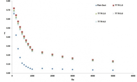
The influences of the Centre trimmed twisted tape inserts on friction factor characteristics are represented in Figure 6. The figure shows the relationship between the friction factor and Reynolds number for different twist ratios for all tube fitted centre trimmed twisted tape and plain twisted tapes. For all cases, friction factor inversely proportionate with the Reynolds number. It could be also seen from the figure that the friction factor was in the similar trend both for the plain twisted tape and the twin twisted tapes inserts. It can also see from the figure that the friction factor inversely proportionate with twist ratio. This is because the attributed to the use of centre trimmed twisted tape inserts with a smaller twist ratio which led to a higher viscous loss near the tube wall regions caused by a stronger swirl flow or turbulence flow and long residence time in the tube.
Figure 6. Variation of friction factor characteristics with Reynolds number of CTTT for different twist ratio
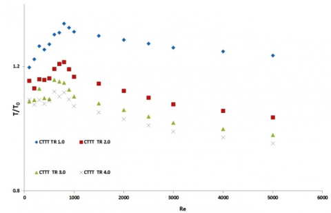
Temperatures were measured at the outlet of the duct. This data after non-dimentionlization (T/T0) has been shown in Figure 7. In all cases non-dimensional temperature is above unity. Higher rise in temperature is obtain for centre trimmed twisted tape (CTTT TR 4.0) in low Reynolds number range, whereas CTTT TR 2.0 and CTTT TR 3.0 shows some promising result in higher Reynolds number range.
Figure 7. Non-dimensional temperature variation with Reynolds number for different spring tapes
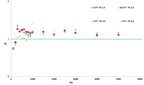
As increment in heat transfer is gradually came across with pressure drop, thermal performance factor (η) is the appropriate parameter used for evaluating the practical use of the twisted tape. The factor is calculated by considering the effect of heat transfer augmentation and the increase of pressure drop, simultaneously. The changing of thermal performance factor with Reynolds number of the tubes equipped with centre trimmed twisted tape and plain twisted tape is shown in Figure 8. By doing the entire computation on trimmed twisted tape and plain twisted tape it was noticed that efficient from the energy point of view and enhancement efficiency was found to be greater than the unity all the time in varied Reynolds number. The efficiency for enhancement above unity indicated that the effect of heat transfer enhancement due to the turbulator was more dominant than the effect of rising friction and vice versa. As expected from Figure 8, the tube inserts with TR 1.0 and TR 2.0 at lower Reynolds number upto about 1000 provided higher thermal enhancement efficiency and at higher Reynolds number (Re 5000) TR 3.0 can be recommended.
Figure 8. Variation of enhancement efficiency (η) with Reynolds number
A computational study have been conducted to check the flow friction and heat transfer characteristics in a centre trimmed twisted tape tube heat exchanger with at different twist ratio, Re ranging from 100 – 5,000. Based on the computational results, findings of this study could be summarized as follows:
i) In results it was found that the friction factor heat transfer, and thermal enhancement efficiency augmented with decreasing twist ratio.
ii) Nusselt number increased with increasing Reynolds number while the opposite trends were found for the case of friction factor.
iii) The Nu/Nu0 augmentation tends to slightly decrease with the rise in Re.
iv) The thermal augmented efficiency for all the cases was more than one, showed that the effect of heat transfer enhancement due to the turbulators was more important than the effect of rising friction and vice versa.
The authors would like to gratefully acknowledge the MCKV Institute of Engineering (MCVIE) for their support in this research.
|
Ap |
plain duct flow cross-sectional area |
|
C |
centre-trimmed |
|
D |
internal diameter of the channel |
|
f |
dimensionless friction factor |
|
g |
acceleration due to gravity |
|
Gr |
Grashof number |
|
Gz |
Graetz number |
|
P |
wavy pitch |
|
hz |
axially local heat transfer coefficient |
|
L |
axial length, length of the channel |
|
m |
mass flow rate |
|
Nu |
Nusselt number |
|
⧍P |
pressure drop |
|
P |
wetted perimeter |
|
Re |
Reynolds number |
|
S |
Entropy |
|
TR |
twist ratio |
|
Greek symbols |
|
|
β |
Synergy angle |
|
Subscripts |
|
|
f |
bulk fluid |
|
i |
inlet |
|
m |
mean |
|
o |
outlet |
|
w |
channel wall |
|
gen |
generation |
[1] Bergles, A. E. and Webb, R. L., “A guide to the literature on convective heat transfer augmentation in advances in enhanced heat transfer-1985,” S. M. Shenkman, J. E. O‘Brien, I. S. Habib and J. A. Kohler, Eds., ASME Symp. Vol., 43, pp. 81-90, 1985.
[2] Bergles, A. E., Nirmalan, V., Junkhan, G. H. and Webb, R. L., “Bibliography on augmentation of convective heat and mass transfer II,” Heat Transfer Laboratory Report HTL-31, ISU-ERI-Ames-84221, Iowa State University, Ames, December 1983.
[3] Bergles, A. E., Jensen, M. K., Somerscales, E. E. C. and Manglik, R. M., “Literature Review of heat transfer enhancement technology for heat exchangers in gas fired applications,” GRI Report GRI 91-0146, Gas Research Institute, Chicago, 1991.
[4] P. Farrell, K. Wert and R. L. Webb, “Heat transfer and friction characteristics of turbulators radiator tubes,” SAE Technical Paper 910917, SAE International Congress, Detroit, MI, USA, 1991.
[5] C. O. Olsson and B. Sunden, “Heat transfer and pressure drop characteristics of ten radiator tubes,” Int. J. Heat Mass Transfer, vol. 39, pp. 3211–3220, 1996. DOI: 10.1016/0017-9310(95)00409-2.
[6] C. O. Olsson and B. Sunden, “Thermal and hydraulic performance of a rectangular duct with multiple V-shaped ribs,” ASME J. Heat Transfer, vol. 121, pp. 1072– 1077, 1998.
[7] S. K. Saha and A. Dutta, “Thermohydraulic study of laminar swirl flow through a circular tube fitted with twisted tapes,” ASME J. Heat Transfer, vol. 123, pp. 417– 427, 2001.
[8] A. G. Patil, “Laminar flow heat transfer and pressure drop characteristics of power-law fluids inside tubes with varying width twisted tape inserts,” ASME J. Heat Transfer, vol. 122, pp. 143–149, 2000.
[9] U. N. Saha, U. N. Gaitonde and A. W. Date, “Heat transfer and pressure drop characteristics of laminar flow in a circular tube fitted with regularly spaced twisted-tape elements,” Exp. Therm. Fluid Sci., vol. 2, pp. 310–322, 1989.
[10] A. W. Date and S. K. Saha, “Numerical prediction of laminar flow in a tube fitted with regularly spaced twisted-tape elements,” Int. J. Heat Fluid Flow, vol. 11, no. 4, pp. 346–354, 1990.
[11] F. Li, W. Meindersma, A. B. de Haan and T. Reith, “Novel spacers for mass transfer enhancement in membrane separations,” J. Membr. Sci., vol. 253, no. 1–2, pp. 1–12, 2005.
[12] P. Sivashanmugam and S. Suresh, “Experimental studies on heat transfer and friction factor characteristics of laminar flow through a circular tube fitted with helical screw-tape inserts,” Appl. Therm. Eng., vol. 26, no. 16, pp. 1990–1997, 2006.
[13] S. Chang, K. W. Yu and M. Lu, “Heat transfer in tubes fitted with single, twin, and triple twisted tapes,” Exp. Therm. Fluid Sci., vol. 18, no. 4, pp. 279–294, 2005.
[14] A. Dewan, P. Mahanta, K. S. Raju and P. S. Kumar, “Review of passive heat transfer augmentation techniques,” Proc. IMechE., Part A, J Power Energy, vol. 218, no. 7, pp. 509–527, 2004.
[15] M. Hong, X. Deng, K. Huang and Z. Li, “Compound heat transfer enhancement of a convergent–divergent tube with evenly spaced twisted tapes,” Chin. J Chem. Eng., vol. 15, no. 6, pp. 814–820, 2007.
[16] M. Rahimi, S. R. Shabanian and A. A. Alsairafi, “Experimental and CFD studies on heat transfer and friction factor characteristics of a tube, equipped with modified twisted-tape inserts,” Chem. Eng. Process., vol. 48, no. 3, pp. 762–770, 2009.
[17] S. Bhattacharyya and S. K. Saha, “Thermohydraulics of laminar flow through a circular tube having integral helical rib roughness and fitted with centre cleared twisted-tape,” Exp. Therm. Fluid Sci., vol. 42, pp. 154–162, 2012.
[18] S. Bhattacharyya, S. Saha and S. K. Saha, “Laminar flow heat transfer enhancement in a circular tube having integral spiral rib roughness and fitted with centre cleared twisted-tape,” Exp. Therm. Fluid Sci., vol. 44, pp. 727–735, 2013.
[19] S. K. Saha, S. Bhattacharyya and P. K. Pal, “Thermohydraulics of laminar flow of viscous oil through a circular tube having integral spiral rib roughness and fitted with centre-cleared twisted tape,” Exp. Therm. Fluid Sci., vol. 41, pp. 121–129, 2012.
[20] Fan, A. W., Deng, J. J., Nakayama, A. and Liu, W., “Parametric study on turbulent heat transfer and flow characteristics in a circular tube fitted with louvered strip inserts,” International Journal of Heat and Mass Transfer, vol. 55, pp. 5205 – 5213, 2012.
[21] Ozisik, M. N., Heat Transfer, Mc-Graw-Hill, 1985.