OPEN ACCESS
Contrapose HRSG for blast furnace gas, according to the basic principle of hydrodynamic calculation of a natural circulation boiler, this paper proposes a hydrodynamic calculation method based on non-uniform heat load distribution. The backflow hydrodynamic calculation is applied to the natural circulation HRSG of hydrodynamic calculation, and the hydrodynamic parameters of each boiler heating district is precisely obtained whether backflow or positive flow. Based on developed software, analyze the regularity of the hydrodynamic characteristic parameters variation is analyzed with the heat load on the HRSG, then the theoretical foundation is provided for the design and perfection of the HRSG.
Blast furnace gas, HRSG, Hydrodynamic.
Currently, the precision and modular computing software has gradually replaced the low precision and step tedious hand calculations graphic on the hydrodynamic calculation of conventional boiler [1, 2]. With the development of boiler thermal calculation and numerical simulation techniques, the heat absorption of the heating surface can be calculated accurately. Therefore, the possibility of the hydrodynamic calculation of natural circulation based on non-uniform heat load distribution can be realized [2].
At present, HRSG has a wide range of applications in the metallurgical and chemical production areas [3], and its operation is gaining attention. On account of the special structure and working conditions of HRSG, in order to ensure the safe operation of it, a particular hydrodynamic calculation should be designed to avoid dangerous situations such as heat transfer deterioration, stagnation or backflow [4, 5]. In this regard, this paper proposes, according to the basic principle of hydrodynamic calculation of natural circulation boiler, a hydrodynamic calculation method based on non-uniform heat load distribution, and establishes a model of hydrodynamic characteristics and simplifies the calculation for the boiler with the downcomer. The model calculates both the positive flow and the backflow, thus realizing the objective to analyze the change of the hydrodynamic characteristic parameters on the interrelated condition at HRSG.
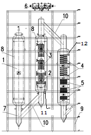
This HRSG is a natural circulation and water tube boiler. The boiler proper is composed of the membrane wall [6]. From the direction of the flue gas flow, high temperature and pressure exhaust gas enters the HRSG by the roof of the blast furnace. Firstly, the exhaust gas enters the settling chamber of HRSG to reduce the temperature and collect dust. Secondly, it runs to the convection chamber I by a linked pipe to transfer heat, then the gas runs to the convection chamber II by the roof of the convection chamber I and the linked pipe to transfer heat again. The structure of the boiler is shown in the Figure 1.
The water system is more complex. Water enters the economizer for heating through the feed water pump and enters the drum, then drops into each cooling chamber of the heating surface respectively by three downcomers. The working fluid is heated through the flue gas, and it runs into the drum by the lead pipe. The saturated steam flows from the steam drum, and is heated in superheater. Because of the typical structure in convection chamber I, the test will analyze and elaborate it.
1. Settling Chamber, 2. Evaporator 1, 3. Superheater, 4. Evaporator 2, 5. Economizer, 6. Drum, 7. Hopper Bottom, 8. Cooled Wall, 9. Steel Frame, 10. Linked Pipe, 11. Chamber I, 12. Chamber II.
Figure 1. Essential Structure Plan of HRSG
3.1 Assumption and simplification of the calculation model
Assuming only consideration of the direction of flow velocity and pressure changes regardless of changes in the radial direction of the working fluid, and the rate and pressure are equal to the flow section [7].
(2) Pressure drop comparing the impact of volume changes in the flow resistance is negligible [8, 9].
(3) Contrapose each division of the riser pipe based on the thermal calculation. The heat load of each pipe is distributed evenly along the length of the tube [10].
(4) Considering the two-phase fluid as homogeneous fluid, and the steam and water have the same equal velocity [11].
(5) The energy loss will not be calculated when the two-phase backflow fluid mixes with the water of the riser pipe [12].
(6) Water is considered as saturated water when the backflow starts in the evaporator. The section has zero rate of vapor content [13].
3.2 Mathematical model of hydrodynamic calculation
The model will establish convection chamber I. As Figure 2(a) shows, the natural circulation loop is comprised of the membrane wall 3, evaporator 6, transfer pipe 7 and 4, supply pipe 2 and 5. The risen system is serial connected respectively by 2,3,4 and 5,6,7, and then parallel connection. They use the only downcomer to constitute the complex circulation loop. The equation set is constituted on the basis of equivalent pressure difference and working fluid [14].
1. Downcomer, 2. Dupply Pipe 1, 3. Cooled Wall, 4. Transfer Pipe 1, 5. Supply Pipe 2, 6. Evaporator, 7. Transfer Pipe 2, 8. Drum.
Figure 2. Model of Hydrodynamic Calculation and Layout Diagram of Evaporator for Convection Chamber I
The water-cooled wall of convection chamber I is a circular arrangement at this HRSG. All of the pipes have the same level of heat, so one hydrodynamic equation is sufficient to calculate it. The length-ways view and the typical cross section of the evaporator is shown in Figure 2(b),(c). In the process of modeling, heat flux density of the heating surface is equal because of the homogeneous velocity of flue gas in the furnace, but the pipe has a different length, causing a non-uniform heat load. According to this assumption, all the evaporator pipes are divided into eight regions on the basis of the different of the lengths, Then all the regions have an even heat load, and the equation is simplified. The number of the equation is reduced from 176 to 8 because of this, and the hydrodynamic character of the all evaporators can be reflected factually by the eight regions. Furthermore, the hydrodynamic parameters can be calculated accurately when the backflow occurs. Based on the same equation of the circulation loop, the only pressure differential equation is explained when it is based on the the risen system 2-3-4 and the downcomer 1.
$\rho^{\prime} g h_{1}-\Delta P_{\mathrm{xj}}=\rho^{\prime} g\left(h_{2}+h_{s 1}\right)+\overline{\rho}_{3} g h_{3}$$+\overline{\rho}_{4} g h_{4}+\Delta p_{y r 1}+\Delta p_{s s 1}+\Delta p_{y c 1}+\Delta p_{f 1}$(1)
where$\rho^{\prime} g h_{1}-\Delta P_{\mathrm{xj}}=\rho^{\prime} g\left(h_{2}+h_{s 1}\right)+\overline{\rho}_{3} g h_{3}$$+\overline{\rho}_{4} g h_{4}+\Delta p_{y r 1}+\Delta p_{s s 1}+\Delta p_{y c 1}+\Delta p_{f 1}$are the length of the respective pipe sections, m; $h_{s 1}$ is the height of the boiling beginning in the riser pipe, m; $\Delta P_{x j}, \Delta P_{y r 1}, \Delta P_{s s 1}, \Delta P_{y c 1}, \Delta P_{f 1}$ are the flow resistance of the respective downcomer section, Pa; $\rho^{\prime}, \overline{\rho}$ are the density of the water and the two-phase fluid in the respective pipe, kg/m3;
The flux of the downcomer is equal to the sum of the riser pipe and the evaporator,
$G_{x j}=G_{s s 1}+G_{s s 2}+\ldots+G_{s s 9}$(2)
When the heat parameters of the working fluid and the structure of the furnace are confirmed, the flow velocity is the only unknown variable in equation 1, so the equation can be simplified as follows:
$\left\{\begin{array}{l}{0=f_{1}\left(w, w_{1}\right)} \\ {0=f_{2}\left(w, w_{2}\right)} \\ {\cdot} \\ {\cdot} \\ {0=f_{9}\left(w, w_{9}\right)} \\ {w A=w_{1} A_{1}+w_{2} A_{2}+\ldots w_{9} A_{9}}\end{array}\right.$(3)
where $\mathcal{W}$ is the flow velocity of the downcomer, $w_{1}$ is the flow velocity of the riser pipe in the water-cooled wall, $w_{2}$, $w_{3}$ …$w_{9}$ are the flow velocity of the riser pipe in the evaporator. Ten unknown numbers are included in ten equations.
The established hydrodynamic model according to non-uniform heat load distribution is universal for the calculation of a complex hydrodynamic circulatory system. The model has been validated by three hydrodynamic calculation examples from appendix two Literature [9]. Tabulation one and Tabulation two are the main parameter comparison tables for the graphic method and software calculation. The flow velocity computational error of water-cooled wall 1 is 3.6% , and the other error is less than 2%. This validation reflects the correctness of the calculation model.
Table 1. Comparison of Results of Different Methods for Flow Velocity
|
|
Water-cooled wall 1 |
Water-cooled wall 2 |
Water-cooled wall 3 |
|
Software Calculation |
0.8195 m/s |
0.8929 m/s |
0.91434m/s |
|
Graphical Method |
0.79 m/s |
0.886 m/s |
0.926 m/s |
|
Error |
0.036 |
0.0077 |
-0.0129 |
|
|
Water-cooled wall 1 |
Water-cooled wall 2 |
Water-cooled wall 3 |
|
Software Calculation |
121.41 Kpa |
123 Kpa |
118.2 Kpa |
|
Graphical Method |
123 Kpa |
122.9 Kpa |
118.1 Kpa |
|
Error |
-0.0131 |
0.0054 |
0.0008 |
5.1 Calculation results contrast for non-uniform heat load and uniform heat load
Tabulation 3 is the distribution of circulatory flow velocity of each partition section of the uniform load calculation model and non-uniform load calculation model on the design conditions of HRSG.
Table 3. Comparison of Circulatory Flow Velocity Calculation Results of Evaporator
|
|
Region 1 |
Region 2 |
Region 3 |
Region 4 |
|
Non-uniform Heat Load |
0.686 m/s |
0.660 m/s |
0.631 m/s |
0.601 m/s |
|
Uniform Heat Load |
0.577 m/s |
0.577 m/s |
0.577 m/s |
0.577 m/s |
|
|
Region 5 |
Region 6 |
Region 7 |
Region 8 |
|
Non-uniform Heat Load |
0.568 m/s |
0.533 m/s |
0.490 m/s |
0.447 m/s |
|
Uniform Heat Load |
0.577 m/s |
0.577 m/s |
0.577 m/s |
0.577 m/s |
5.2 Result analysis
The following major change is the heat load of the blast furnace gas HRSG, and the general rule can be obtained by analysis and comparison of the hydrodynamic character parameter.
Figure 3 shows the changes in flow velocity and the heat load at the riser pipe. The eight regions are the evaporator, and number nine is the water-cooled wall. The flow velocity of the riser pipe is increased because of the larger density contrast between the riser pipe and the backflow pipe when the heat load is increased. Furthermore, the sensitivity of water-cooled wall is larger than the evaporator to heat load change. At the boiling point, the eighth region is taken as an example because of the least heat load. Figure 4 is the condition of changes in the height of boiling point along with the heat load at the evaporator and water-cooled wall. The height of boiling point will come to the minimum because of the higher heat load and quantity of heat. Based on the above analysis, the higher heat load led to smaller density of riser pipe and larger density contrast between riser pipe and backflow pipe. Thus, the hydrodynamic of natural circulation will have more power. Finally, the circulatory flow velocity is increased, the height of boiling point is decreased, and the sensitivity of the water-cooled wall is larger than the evaporator to heat load change.
Figure 3. Flow velocity along with heat load
Figure 4. Height of boiling point along with heat load
Figure 5. Pressure drop of downcomer along with heat load
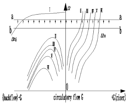
Figure 6. Haracteristic of backflow and positive flow
Figure 5 shows that the pressure drop of downcomer and water-cooled wall is decreasing when the heat load is increasing; that is, operational pressure drop of the HRSG is decreasing when the heat load is increasing. Because the difference of the pressure drop at the downcomer is decreasing between gravity pressure drop and flow resistance pressure drop, and the pressure drop does not change, the flow resistance pressure drop is increasing when the heat load is increasing.
Figure 6 shows the characteristic of backflow and positive flow at each region of the evaporator. The horizontal axis is the flow and vertical coordinates is the pressure drop; Ⅰis the downcomer characteristic curve of pressure drop; Ⅱ,Ⅲ,Ⅳ,Ⅴ,Ⅵ are characteristic curves of the regions eight, six, four, two and one respectively. When the natural circulation is running stably at pressure drop a-a, the pressure drop will decrease because of the increased heat load. Furthermore, there are three or two points of intersection between pressure drop b-b and characteristic curve Ⅱ, so there are three or two solutions for region eight. Finally, the possible backflow of region eight and water-cooled wall of the design structure when the design heat load is 1.1 times is calculated, showing that the blast furnace gas HRSG can operate safely at 1.1 times, as per the follow tabulation:
Table 4. Safety margin calculation table
|
|
Water-cooled wall |
Region eight |
|
Convergence Result |
157935.63Pa |
27524.54Pa |
|
Maximum Pressure Drop |
131728.08Pa |
25167.17Pa |
|
Security Coefficient |
1.19 |
1.09 |
Contraposing a blast furnace gas HRSG, a hydrodynamic calculation method has been proposed based on the principle of non-uniform heat load distribution. A universal hydrodynamic model has been established to calculate the positive flow and backflow. The hydrodynamic parameters of each boiler heating district has been precisely obtained with greater precision and efficiency.
The established model calculates hydrodynamic of a blast furnace gas HRSG in detail. In the case of heat load changing, the model analyzes the change of the hydrodynamic characteristic parameters of the interrelated condition at the HRSG. Calculative results show that the blast furnace gas HRSG can operate safely at 1.1 times, and dangerous situations such as backflow and stagnation will not occur.
[1] H. W. Gao, “Design of five MW blast furnace gas HRSG,” Jiangsu Boiler, vol. 26, no. 1, pp. 20-22, Feb. 2009.
[2] K. Wang, “Development of design software of waste heat boiler for heating furnace,” M.S. thesis, Dept. Northeastern Univ., Changchun, China, 2011.
[3] Design and Operation of Exhaust Heat Boiler, 1st ed., Metallurgical Design Institute, Beijing, China, 1982, pp. 1-16.
[4] Singh, H. N., Kumar, Ravi and Mohanty, Bikash, “Pool boiling heat transfer on wire screen wrapped horizontal tubes,” International Journal of Heat and Technology, vol. 24, no. 1, pp. 129-133, 2006.
[5] Z. W. Wang, “Safety check calculation and optimization of special phosphorus furnace natural water cycle,” Chemical Engineering, vol. 39, no. 3, pp. 91-94, 2011.
[6] Practical Handbook of Boiler, 2nd ed., Shanghai Power Equipment Research Institute, Shanghai, China, 2009, pp. 530-574.
[7] Y. K. Sun, “Commercial operation test and performance analysis of a 200 MWe Super-high-pressure circulating fluidized bed boiler,” Industrial &, Engineering Chemistry Research, vol. 50, no. 6, pp. 3517-3523, 2011. DOI: 10.1021/ie101271x.
[8] Boiler Unit Standard Method for Hydraulic Calculation, 1st ed., Shanghai Power Equipment Research Institute, Shanghai, China, 1981, pp. 193-199.
[9] Power Plant Boiler Hydrodynamic Calculation Method 2nd ed., Shanghai Power Equipment Research Institute, Shanghai, China, 1984, pp. 23-35.
[10] V. N. Baranov, “Studying the hydrodynamic instability of heating surfaces used in a P-57 Boiler,” Thermal E ngineering, vol. 58, no. 12, pp. 988-997, 2011. DOI: 10.1134/S0040601511120044.
[11] Rui Cao, “Performance characteristics analysis of supercritical boiler water wall,” Mechatronics and Materials Processing, vol. 3, pp. 2248-2251, 2011.
[12] Aquaro, D. and Pieve, M., “Compact heat exchangers optimization: Developing a model for the thermal-fluid dynamic sizing,” International Journal of Heat and Technology, vol. 25, no. 1, pp. 9-18, 2007.
[13] Aminossadati, S. M. and Ghasemi, B., “Computational modelling of heat transfer in a partially partitioned enclosure,” International Journal of Heat and Technology, vol. 26, no. 2, pp. 51-58, 2008.
[14] Principle and Calculation of Boiler, Shanghai Power Equipment Research Institute, Shanghai, China, 2003, pp. 402-662.