OPEN ACCESS
Having the premise of the certain acoustic performance, a muffler should make the pressure loss as small as possible. A simulation model of a fork truck muffler with a complex structure is established. Based on the finite volume method, multi- dimensional numerical simulation regarding velocity field and pressure field of steady flows for a muffler is performed using CFD (computational fluid dynamic method). Flow characteristics and pressure distribution of the muffler are analyzed. It is found that the vortex inside the muffler creates a great pressure loss. With the increases of inlet gas flow rate , the pressure loss of the muffler increases gradually. The internal structure of the muffler is redesigned for obtaining the optimized structure on the basis of analysis. The influences of the inner tube length on the flow and pressure loss of muffler are researched. The study will provide a theoretical basis for designing a complex muffler.
Complex muffler, Velocity field, Pressure field, Structure improvement.
Reactive mufflers are widely used in the exhaust system of internal combustion engines. Generally speaking, a muffler structure used in engineering machinery is very complex. Mufflers can cause a decrease in engine power and economy while reducing noise at the same time. Therefore, a detailed study of the flow characteristics of the muffler is very important [1] [2]. For practical complex mufflers, the internal flow is three-dimensional and unsteady. The reports on the flow field and pressure distribution of muffler are rare. Therefore it is important to simulate the speed characteristics and pressure distribution of exhaust muffler [3]. Domestic unreasonable designs can be found by analyzing the flow characteristics of a muffler, and it can provide the necessary theoretical support for the optimized design of a muffler [4]. Three-dimensional CFD simulation technology will reveal new ideas and directions for the optimal design of modern engineering machinery parts [5]. A reactive perforated muffler was investigated numerically and experimentally. Back pressure was obtained based on the flow field analysis and was also compared with experimental results [7]. The performance of automotive exhaust muffler was analyzed based on ANSYS [8]. The flow field was calculated with the CFD method, and the aerodynamic noise was evaluated based on the simulation results [9]. Two typical mufflers were investigated by means of a three-dimensional numerical simulation integrated CFD (computational fluid dynamics) and CAA (computational aeroacoustics) [10]. A monolithic muffler simulation calculation model was introduced in the paper. The pressure loss and internal flow field of the muffler were obtained by CFD simulation [11]. An analysis was made of the effects of the length, turning form and the collocation on the cooling performance and the resistance characteristics [12]. Three-dimensional numerical simulation of the internal turbulent fluid field was performed by using Fluent of computational fluid dynamics software [13]. Most of the authors of above literature researched the internal flow field of existing muffler only, but they did not improve the structure of the original muffler based on the analysis. Therefore, obtaining the optimized structure of the muffler is very meaningful on the basis of comparison.
Excessive pressure loss of exhaust muffler causes a decrease in engine power so as to increase the fuel consumption of engineering machinery. Thus, a muffler with low pressure loss is the goal of designers. An empirical formula is used to calculate the pressure loss of the muffler in the traditional method, but its accuracy is relatively low, and pressure loss problems of complex mufflers cannot be solved. While the test method has high accuracy and reliability, it is not suitable for predicting the flow characteristics of mufflers. In this paper, a numerical simulation of fluid dynamics performance for a fork truck muffler is conducted based on the theory of computational fluid dynamics. The distribution of velocity and pressure fields in the interior of the muffler is obtained. Based on the analysis results, the internal structure of a conventional muffler is improved.
Computational fluid dynamics is a new discipline which combins classical fluid dynamics and numerical methods. In this paper, the integration of equation for the control volume is used to derive a discrete equation by using a finite volume method which is used widely in numerical calculation of fluid and in current commercial CFD software.
2.1 The equations of muffler flow field
For the stable dimensional compressible flow, there are mass and momentum conservation equations that are Reynolds-averaged [14].
$\frac{\partial}{\partial x_{j}}\left(\rho u_{j}\right)=0$ (1)
$\frac{\partial}{\partial x_{j}}\left(\rho u_{j} u_{i}-\tau_{i j}\right)=-\frac{\partial p}{\partial x_{j}}+s_{i}$ (2)
Where $S_{i}$ is the source term, here it represents resistance; $\tau_{i j}$ is the stress tensor, and there are following equations for Newtonian flow.
$\tau_{i j}=2 \mu\left(s_{i j}-\frac{1}{3} \frac{\partial u_{k}}{\partial x_{k}} \delta_{i j}\right)-\overline{\rho u_{i}^{\prime} u_{j}^{\prime}}$ (3)
Where μ is the molecular dynamic viscosity coefficient; $\delta_{i j}$ is Kroneker number; $\overline{\rho u_{i} u_{j}}$ is Reynolds stress tensor;$s_{i j}$ is fluid strain rate tensor, which is determined by the following equation.
$s_{i j}=\frac{1}{2}\left(\frac{\partial u_{i}}{\partial x_{j}}+\frac{\partial u_{j}}{\partial x_{i}}\right)$ (4)
2.2 Turbulence model of muffler flow field
The Reynolds stress is calculated by using a standard κ-ε model to close the flow control equation as follows:
$\overline{\rho u_{i}^{\prime} u_{j}^{\prime}}= -2 \mu_{t} s_{i j}+\frac{2}{3}\left(\mu_{t} \frac{\partial u_{k}}{\partial x_{k}}+\rho k\right) \delta_{i j}$ (5)
Where $\mu_{t}$ is the turbulent viscosity coefficient, which is determined by the following equation.
$\mu_{t}=\frac{c_{\mu} \rho \kappa^{2}}{\varepsilon}$ (6)
Where κ,ε is turbulent kinetic energy and turbulent energy dissipation rate respectively. The transport equation is as follows.
$\frac{\partial}{\partial x_{j}}\left(\rho u_{j} \kappa-\frac{\mu_{e f f}}{\sigma_{\kappa}} \frac{\partial \kappa}{\partial x_{j}}\right)= \mu_{t} s_{i j} \frac{\partial u_{i}}{\partial x_{j}}-\rho \varepsilon-\frac{2}{3}\left(\mu_{t} \frac{\partial u_{i}}{\partial x_{i}}+\rho \kappa\right) \frac{\partial u_{i}}{\partial x_{i}}$ (7)
$\frac{\partial}{\partial x_{j}}\left(\rho u_{j} \varepsilon-\frac{\mu_{e f f}}{\sigma_{\varepsilon}} \frac{\partial \varepsilon}{\partial x_{j}}\right) =c_{\varepsilon 1} \frac{\varepsilon}{\kappa}\left\{\mu_{t} s_{i j} \frac{\partial u_{i}}{\partial x_{j}}-\frac{2}{3}\left(\mu_{t} \frac{\partial u_{i}}{\partial x_{i}}+\rho \kappa\right) \frac{\partial u_{i}}{\partial x_{i}}\right\} -c_{\varepsilon 2} \rho \frac{\varepsilon^{2}}{\kappa}+c_{\varepsilon 4} \rho \varepsilon \frac{\partial u_{i}}{\partial x_{i}}$ (8)
Where $\mu_{e f f}=\mu+\mu_{t}$ ; The empirical coefficients of $C_{\mu}$ ,$\sigma_{k}$ ,$\sigma_{\varepsilon}$ ,$C_{\varepsilon 1}$ ,$C_{\varepsilon 2}$ and $C_{\varepsilon 4}$ are determined according to Table 1.
Table 1. Coefficient of experience [14]
|
$C_{\mu}$ |
$\sigma_{k}$ |
$\sigma_{\varepsilon}$ |
$C_{\varepsilon 1}$ |
$C_{\varepsilon 2}$ |
$C_{\varepsilon 4}$ |
|
0.09 |
1.0 |
1.22 |
1.44 |
1.92 |
-0.33 |
3.1 The object of research
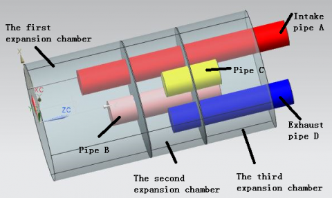
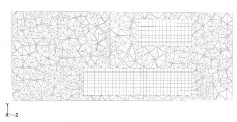
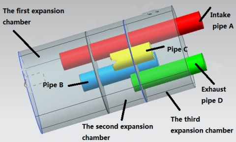
The three-dimensional model of a muffler established is shown in Figure 1. The muffler is divided into three chambers by two separators. The length of the first expansion chamber is 177mm, the length of the second expansion chamber is 100mm and the length of the third expansion chamber is 127mm. The muffler contains four tubes with a diameter of 46 mm. The red tube is the intake pipe A with a length of 380 mm. The blue tube is tube B linking chamber 1 to chamber 3, with a length of 200 mm. The yellow tube is tube C linking chamber 2 to chamber 3, with alength of 100 mm. The green pipe is exhaust pipe Dwith a length of 220 mm. Figure 2 is a section mesh graph of the muffler. The inner tube of the muffler is a cylinder with a relatively simple and regular structure. It is suitable to use a structural grid to divide the inner tube so that the mesh quality and speed generated is relatively high. Because the three chambers are irregular bodies, it is not suitable to use structured grids to divide them, so the unstructured grids are used to divide the three chambers.
Figure 1. Three-dimensional model of muffler
Figure 2. A section mesh graph of the muffler
3.2 Boundary conditions and initial conditions
Equations are solved by using the SIMPLEC algorithm using the standard k-e turbulence model to simulate. Inlet boundary condition is set to the entry speed. Outlet boundary condition is set to a pressure outlet with a gauge pressure value of 0.
3.3 Calculation results
(1) The internal pressure distribution of the muffler
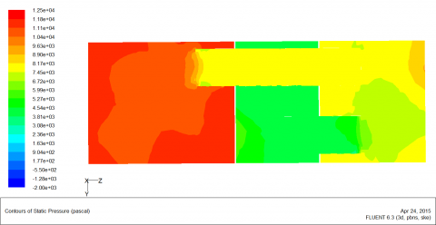
The pressure loss is the pressure difference between the gas inlet and outlet of the muffler. Too much pressure loss from the muffler can seriously affect engine power. Figures 3 (a) and 3 (b) show the pressure contours of the muffler when the inflow rate is 50 m / s. Figure 3 shows that the pressure drop between the three chambers is relatively large. The internal pressure of each expansion chamber is relatively stable and the distribution is relatively uniform. It can be concluded that one cause of a significant reduction in pressure between the two chambers is that the airflow through the inner tube creates a greater pressure loss. Mutations in the gas flow cross-section can have a greater pressure loss. If the flow direction and the gas flow conditions change with a greater degree, it not only will generate the eddy current phenomenon, but also consume more energy.
(a) Section X=0
(b) Section Y=0
Figure 3. Pressure contours of muffler center plane
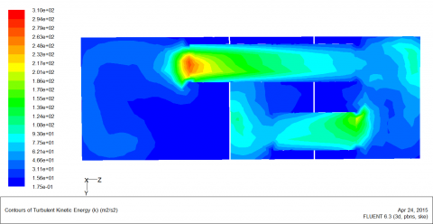
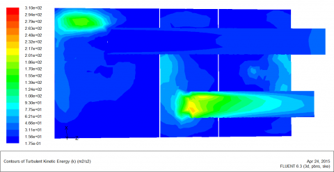
Figures 4 (a) and 4 (b) show the turbulence intensity contours of the muffler when the inflow rate is 50 m / s. The following areas of turbulence intensity are relatively large: left exit region of tube A, end regions of tubes B, C and D. the airflow in strong turbulence region consumes more energy.
(a) Section X=0
(b) Section Y=0
Figure 4. Turbulence intensity contours of muffler center plane
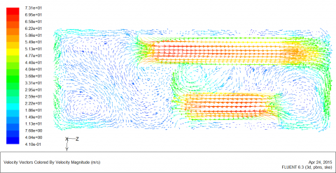
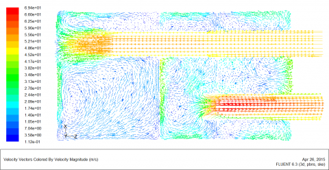
(2) Gas flow characteristics inside the muffler
Airflow velocity and regeneration noise of gas have a direct relationship, which is the main indicator that is also used to evaluate the regeneration noise. The airflow rate will directly affect the performance of the muffler, and excessive air velocity will regenerate noise so as to reduce muffler performance. It is necessary to analyze the velocity field of the muffler. Figures 5 (a) and 5 (b) show the velocity vector of the internal muffler. The figure shows that high flow velocity regions are mainly distributed in the four tubes. As can be seen in Figure 5, both the left upper region of tube A and the left end region of tube C have two distinct vortexes. This is the result of the airflow colliding with the wall directly. The distribution area of swirl point and turbulence intensity is the same.
(a) Section X=0
(b) Section Y=0
Figure 5. Velocity vector of muffler center plane
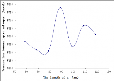
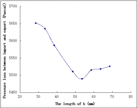
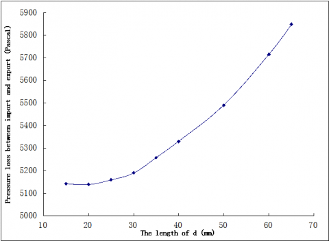
Vortex is the main reason generating pressure loss and the secondary noise of the muffler. Based on the analysis results, the following structure of the muffler will be improved. They include the length of tube A in the first chamber (a), the length of tube C in the second chamber (b) and the length of tube D in the second chamber (d). The first improvement is the length of the tube A at 118.5 mm, 108.5 mm, 98.5 mm, 78.5 mm, 68.5 mm and 58.5 mm respectively. Figure 6 shows the change curve of muffler pressure loss as the length of A. When A is equal to 78.5 mm,the pressure loss of the muffler is minimal. Figure 7 shows the change curve of muffler pressure loss as the length of B. When B is equal to 53.5 mm,the pressure loss of the muffler is minimal. Figure 8 shows the change curve of muffler pressure loss as the length of D. When D is equal to 20 mm,the pressure loss of the muffler is minimal.
Figure 6. The change curve of muffler pressure loss as the length of a.
Figure 7. The change curve of muffler pressure loss as the length of b.
Figure 8. The change curve of muffler pressure loss as the length of d.
5.1 Contrast of pressure loss of muffler under the same velocity
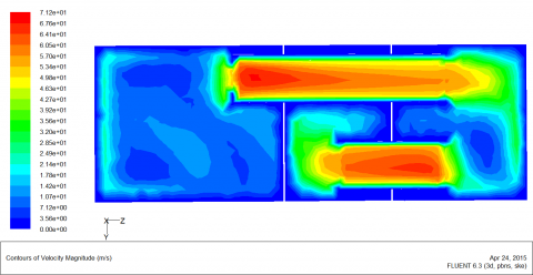
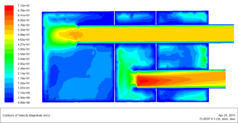
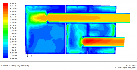
Figure 9 and Figure10 show the velocity contours of the muffler when the flow rate is equal to 50 m/s. It can be seen that the improvement in air velocity distribution of the muffler is similar to that of the original muffler. However, improvement in the pressure loss of the muffler is reduced significantly. It shows the improvement of aerodynamic performance of the muffler is greater.
(a) The original muffler
(b) The improved muffler
Figure 9. The velocity contour of muffler with the section of X direction
(a) The original muffler
(b) The improved muffler
Figure 10. The velocity contour of muffler with the section of Y direction
Figures 11 and 12 show the velocity vector of a muffler when the flow rate is equal to 50 m/s, showing that swirl velocity generated in the left side of tube A and pipe C of the improved muffler has a certain degree of reduction compared to the original muffler. The structural improvement of the muffler not only reduces the pressure loss inside the muffler, but also enhances the aerodynamic performance of the muffler.
(a) The original muffler
(b) The mproved muffler
Figure 11. The velocity vector of muffler with the section of X direction
(a) The original muffler
(b) The improved muffler
Figure 12. The velocity vector of muffler with the section of Y direction
5.2 Pressure loss comparison of muffler when the flow rate is different
Table 2 shows the pressure loss comparison between the original muffler and the improved muffler. The inlet flow velocity of simulation is 10 m/s, 30 m/s, 50 m/s, 70 m/s, 90 m/s. When the intake flow velocity is increased, the pressure loss of the muffler between the intake and exhaust ports will also rise. For any flow velocity, pressure loss of the improved muffler is smaller than that of the original muffler. When the inlet velocity is very large, the drag reduction effectiveness of the muffler is improved more. The study shows that the aerodynamic performance of the improved muffler has been improved at both low and high speeds.
Table 2. The pressure loss comparison between original muffler and the improved muffler
|
Exhaust velocity(m/s) |
Pressure loss of original muffler (pascal) |
Pressure loss of the improved muffler (pascal) |
|
0 |
0 |
0 |
|
10 |
235.82448 |
209.22595 |
|
30 |
2090.6287 |
1856.5557 |
|
50 |
5781.0137 |
5139.4731 |
|
70 |
11288.342 |
10040.176 |
|
90 |
18627.885 |
16563.053 |
Figure 13 shows the improved model of the muffler. The total length of the improved intake pipe A is 370 mm, the total length of the improved pipe B is 200 mm, the total length of the improved tube C is 105 mm and the total length of the improved pipe D is 190 mm.
Figure 13. The improved model of muffler.
1. The mathematical model and the simulation model of the internal flow field for a fork truck muffler are established based on the finite volume method. Pressure distribution and airflow characteristics of the muffler are determined. The cause of generating pressure loss inside the muffler is identified. The variation curve of muffler pressure loss as the length of the inner tube is determined.
2. A large pressure loss is generated inside the muffler due to vortex. At the same time, the vortex is the main cause of noise production, so the muffler structure that does not produce vortexes should be adopted.
3. The inlet velocity of the muffler has a great influence on the pressure loss of the muffler. The pressure loss of the muffler increases with the increase of the inlet flow rate.
4. The pressure loss of the improved muffler is decreased, and the muffler structure with better aerodynamic performance is obtained. This proves that the CFD simulation results and analysis can provide the guidance for designing a complex muffler.
This paper is supported by the National Natural Science Foundation of China (Grant No.51375411;51205336) and the education and research programs for middle-aged and young scholars of Fujian province of China (grant No. JA15367).
1. LIU Peng-fe and BI Chuan-xing, Numerical Analysis of Acoustic Performance and Aerodynamic Characteristics of Automobile’s Muffler. NOISE AND VIBRATION CONTROL, vol. 29, pp. 99-102, 2009. DOI: 10.3969/j.issn.1006-1355.2009.04.028.
2. BI Rong, LIU Zheng-shi, WANG Min, ZHAO Hu, QIN Guang-yu, The Numerical Simulation on Acoustic and Resistance Performance of Exhaust Muffler, NOISE AND VIBRATION CONTROL, Vol. 28, pp. 111-114, 2008. DOI: 10.3969/j.issn.1006-1355.2008.01.032.
3. LI Yi-nong, LU Ming, ZHENG Lei, CHEN Qing-ping, ZHENG Ling, Numerical simulation of the flow and temperature fields in an automotive exhaust muffler, JOURNAL OF CHONGQING UNIVERSITY (NATURAL SCIENCE EDITION), Vol. 31, pp. 1094- 1097, 2008. DOI: 10.11835/j.issn.1000- 582X.2008.10.002.
4. Gu Fang, Liu Botan, Pan Shujie, Numerical Simulation and Optimal Design for Automotive Exhaust Systems, AUTOMOTIVE ENGINEERING, vol. 29, pp. 950-955, 2007. DOI: 10.3321/j.issn:1000-680x.2007.11.006.
5. GU Fang, LIU Bo-tan, LI Hong-liang, PAN Shu-jie, Structural Analyses for the Vehicle Exhaust System Based on CFD Simulation, TRANSACTIONS OF CSICE, vol. 25, pp. 358-362, 2007. DOI: 10.3321/j.issn:1000- 0909.2007.04.012.
6. Shuai Shijin, Wang Jianxin, Zhuang Renjun, Application of CFD to the Optimal Design of Automotive Catalytic Converters, AUTOMOTIVE ENGINEERING, vol. 22, pp. 129-133, 2000. DOI: 10.3321/j.issn:1000-680X.2000.02.014.
7. Verma Abhishek and M. L. Munjal, Flow-Acoustic Analysis of the Perforated-Baffle Three-Chamber Hybrid Muffler Configurations, SAE International Journal of Passenger Cars-Mechanical Systems, vol.8, pp.370-381, 2015. DOI: 10.4271/2015-26-0131.
8. Ma J. H., Guo P., Analysis of Performance of Automotive Exhaust Muffler Based on ANSYS Finite Element, Applied Mechanics and Materials, vol. 509, pp. 118-122, 2014. DOI: 10.4028/www.scientific.net/AMM.509.118.
9. Wang C. N., Tse C. C., Chen S. C. Flow Induced Aerodynamic Noise Analysis of Perforated Tube Mufflers, Journal of Mechanics, vol. 29, pp. 225-231, 2013. DOI: 10.1017/jmech.2012.133.
10. Yang Y., Sun H., Three-Dimensional Aeroacoustic Numerical Simulation of Flow Induced Noise of Mufflers, Parallel Computational Fluid Dynamics, vol. 405, pp. 276-286, 2014. DOI: 10.1007/978-3-642- 53962-6_24.
11. Li X. Q., Dong D. D., Gu M. J., et al., Study on the Flow Characteristics of the Monolithic Muffler in Train Air Conditioning Duct, Advanced Materials Research, vol. 462, pp. 300-306, 2012. DOI: 10.4028/www.scientific.net/AMR.462.300.
12. He G., Wang X. C., Shi X. Y., Cooling Performance of Diesel Exhaust Water-Collecting Box and Its Influencing Factors, Journal of Naval University of Engineering, vol. 24, pp. 64-67, 2012. DOI: 10.3969/j.issn.1009-3486.2012.01.013.
13. Li S. X., Hou Y. Z., Zhang J. H., et al, Flow Field Numerical Simulation and Performance Study of Two- Stage Superheated Electrical Steam Trap, Advanced Materials Research, vol. 774, pp. 271-274, 2013. DOI: 10.4028/www.scientific.net/AMR.774-776.271.
14. Bian Ming, Wang Zhicheng, Gao Hongge, Analysis for Muffler of 1P68F Small Gasoline Engine, Small Internal Combustion Engine and Motorcycle, vol. 38, pp. 68-69, 2009. DOI: 10.3969/j.issn.1671- 0630.2009.03.020.