Atiyah Altayf*![]() | Hafedh Trabelsi
| Hafedh Trabelsi![]() | Jihed Hmad
| Jihed Hmad![]() | Chellali Benachaiba
| Chellali Benachaiba![]()
© 2024 The authors. This article is published by IIETA and is licensed under the CC BY 4.0 license (http://creativecommons.org/licenses/by/4.0/).
OPEN ACCESS
Addressing the challenge of meeting power demand with high reliability at low cost in Renewable energy (RE) generation is vital issue. The Autonomous Hybrid Energy Storage System (AHESS) to cover electrical deficit in Zigen clinic in southern Libya is introduced. It designed to produce 4 kW. The system comprises of photovoltaic (PV), Battery Energy Storage System (BESS) Flywheel Storage System (FESS) and Supercapacitance Storage System (SCSS). Six PV-BESS combinations, six criteria and three scenarios are studied. The research aim is to find the optimal PV-BESS combination based on low cost and high reliability. Multi-Criteria Decision Methods (MCDM) is implemented to select the optimal combination. The study utilizes Net Present Costs (NPC), Loss Power Supply Probability (LPSP), and Levelized Cost of Energy (LCOE) to assess each criterion. Six combinations of AHESS are implemented in MATLAB. Three MCDM methods are used to determine the optimal sizing of PV-BESS. Simulation results show that 30 PV panels and BESS 60 Ah are the optimal choices based on these results NPC = 19801 \$/kWh, LPSP = 0.104 \$/kWh, and LCOE = 0.032 \$/kWh.
TOPSIS, ARAS, SVNS, reliability, MCDM, renewable energy, flywheel, intelligent selection
The cost of installation and the reliability of an AHESS system are the main factors in its implementation. To determine the correct number of AHESS components, that might help to decrease the net present cost and increase the reliability of the system. A control system is implemented to reduce costs and increase reliability [1]. An autonomous system, PV, Wind Turbine (WT), SCSS, BESS, and hydrogen tank are presented to minimize costs and increase reliability. BESS is reduced to 56%, and the level of hydrogen is increased to 98% [2]. Selecting a suitable battery for a renewable hybrid energy storage system by using MCDM based on different criteria is implemented [3]. Based on the MCDM analysis, selecting the BESS according to customer opinion is implemented [4]. MCDM is used to select the RE system projects based on four main criteria and 30 sub-criteria, The MCDM selects social acceptance, net presented cost, and noise which have a high impact [5]. Nine configurations of Energy Storage System (ESS) are implemented with MCMD based on ten economic-reliability-environmental criteria to select the optimal configuration [6]. The selection of RE source for the RE power plant is conducted with five RE sources, and six criteria (efficiency, emission, production, cost, land, and maintenance) are analyzed with MCDM to select the proper Renewable Energy Sources (RES) for the plant [7]. AHESS for remote villages in India is selected by MCDM based on the three criteria of cost, investment, and environmental impact. The selected cost is \$0.21/kWh [8]. Six barriers criteria and nineteen sub-criteria prevent the RE system installation in Malawi; the Technique for Order Preference by Similarity to Ideal Solution (TOPSIS) is implemented to select the high-impact barrier. The economic and investment costs are determined [9]. A study in Ghan for five different types of RE sources with thirteen criteria was implemented with MCDM, and the result was that the hydro source was the optimal one [10]. To reduce the carbon emissions caused by transportation, a suitable battery-electric vehicle is studied based on its economic and technical specifications. MCDM is applied to select the suitable battery-electric vehicle [11]. Off-grid generates 5.75 kW with a PV, and a hydrogen Fuel Cell (FC) system is applied based on the LCOE and lowest NPC [12]. To develop the battery’s aging, hybrid PV/BESS with FESS and without FESS are presented. The BESS lifetime has improved by 1.72% and increased by two years with a low cost of 22,128.54 and 1.82% of LPSP [13]. An AHESS of PV/WT/BESS/FESS is introduced to minimize the total cost, and an operation cost is introduced [14]. Two system configurations to cover ruler healthcare in Northern Nigeria, PV/Deasil Generator (DG)/BESS and WT/DG/BESS, are presented to select the economic configuration based on the total cost [15]. Three different types of BESS are used with the off-grid system: PV, FC, and BESS to determine the appropriate type, it is conducted based on reliability and economic factors. The results showed the lithium iron phosphate battery with fuel cell and retired electric vehicle battery are more economical with LPSP < 1%. The LPSP from 10% to 0.98% is very high at 12745$ [16]. To minimize the LCOE of an AHESS, the power pinch analysis is applied in literature [17]. Two loops of optimization are implemented. Energy management strategy, economic model predictive control, and Genetic Algorithm Optimization (GAO) are used to find the optimum numbers of components [18]. Three different loads are applied to PV/BESS with GAO to find the optimal sizing based on economic, residential, and industrial loads [19]. Nine configurations of PV / WT / BESS / SCSS are implemented in Hybrid Optimization of Multiple Energy Resources (HOMER) based on technical and economic concepts [20]. PV/BESS configuration is implemented based on technical and economical concepts to satisfy village demand [21]. As a critic, most of the previous papers on AHESS systems used the PSPL, LCOE based on various BESS, configurations, cost to select the optimal solution. To select the number of PV panels with BESS capacity based on six related parameters such as NPC, LPSP and LCOE is not supported therefore PV/BESS with MCDM methods for six criteria and 10 sub-criteria are introduced.
The research presented in this paper focuses on the implementation of MCDM techniques, specifically F- Single Value Neutrosophic Logic Linear Scale Transformation, Max Method (F-SVNS), Additive Ratio Assessment (ARAS), and TOPSIS, to determine the optimal number PV and BESS capacity configuration for AHESS. The study aims to address the energy needs of the Zegin village clinic in south Libya by proposing a system design with 4 kW. The proposed system includes different numbers of PV panel ranging from 20 to 36 panels, and BESS capacities from 40 to 75 Ah. In this proposed system, fixed FESS and SCSS are maintained constant.
This study aims to select the most suitable PV number and BESS capacity based on six main criteria and 10 sub-criteria. These criteria include LCOE, NPC, LPSP, Current consumption (I), Charging Energy (Q), and Discharging Time (DT). By evaluating these criteria, the optimal system configuration AHESS should meet the energy demand of the Zegin village clinic.
The main motivations behind this research lie in addressing the pressing need for sustainable and reliable energy solutions in remote locations. The motivations and contribution of this study can be summarized as following.
-Three intelligent methods for decision-making MCDM have been implemented to ensure selection accuracy: F-SVNS, TOPSIS, and ARAS. These methods have been applied to six combinations, labelled PV1 to PV6 based on six factors: NPC, LCOE, LPSP, I, DT, and Q.
-The criteria weights selection is a critical undertaking for decision-makers. The MCDM has been used for different purposes, such as determining the optimal RE reign, RE economic, political, and social aspects. Study on reliability and economics for BESS, Hydrogen Storage System (HSS), and DG without considering the number of PV and WT [6]. The most cost-effective renewable energy sources (PV, WT, biomass, solar thermal, and hydropower) have been implemented [10]. All literature studies do not take the PV panel numbers and the battery capacity based on NPC, LCOE, LPSP, I, DT, and Q into consideration therefore, this study is unique because it fills the gap of knowledge in AHESS.
The applicability methodology's effectiveness is demonstrated, through its application in a case study, specifically focusing on the PV-BESS selection for the Zigen clinic's AHESS. This case study involves handling uncertain, indeterminate, and inconsistent information.
The article is organized into nine sections. The introduction and literature review are presented in the first section. The system description is located in the second part. The third section covers AHESS system modelling. The fourth section describes the system cost. The data set for the system is organized in the fifth section. MCDM methodology and applications are covered in sections six and seven, respectively. Finally, the eighth and ninth sections summarize the results and conclusions.
The AHESS comprises variable component PV, BESS, and constant component FESS, and SCSS. This proposed system integrates three distinct ESS technologies to capitalize on their unique strengths and advantages in charging and discharging capabilities. The FESS, known for its high efficiency of approximately 95%, minimal maintenance requirements, and extended lifespan. The BESS and SCSS complement each other in the system, each offering unique characteristics to enhance overall performance. The BESS mainly functions as a backup generator during periods of solar energy unavailability. On the other hand, the SCSS characterizes attributes such as low energy density, high power density, and rapid responsiveness, it is quickly adapting the changes in power demand. One of the key advantages of the proposed AHESS system is its environmentally friendly, as it operates without the need for fossil fuels, thereby promoting environmental sustainability. To ensure optimal system performance, the control system is implemented to manage the charging and discharging of the ESS.
Table 1. Clinic power consumption
|
Item |
NO |
Power Consump./W |
Working Hours |
Item Total Power/Wh |
|
Computer |
1 |
500 |
3 |
1500 |
|
Printer |
1 |
450 |
1 |
450 |
|
Bulb |
6 |
10 |
8 |
480 |
|
Abdominal Ultrasound |
1 |
400 |
1 |
400 |
|
Air condition |
1 |
1000 |
2 |
2000 |
|
Slit Lab. |
1 |
1650 |
0.5 |
820 |
Figure 1. Average daily Ampere consumption of the clinic
Table 1 illustrates the load profile of electrical equipment and the clinic's electricity consumption. With a designed capacity to produce 4 kW to meet the clinic's demand load, the average ampere consumption throughout the year is shown in Figure 1, fluctuating around 8.5 A at 380 V AC, with an average power consumption of approximately 3230 W. Notably, the peak load during the year reaches up to 3914 W, with a maximum current draw of 10.3 A, while the system generates around 4180 W at 11 A and 380 V AC. Figure 2 presents a schematic diagram of the AHESS, depicting the schematic layout of the six PV and BESS criteria under consideration.
Figure 2. Schematic diagram of the proposed system
3.1 Photovoltaic component
PV is widely used, especially in sunny regions like Africa. There are two types of PV methods: The Single-diode Method (SDM) and the Double-diode Method (DDM) [22]. the solar cells temperature has a significant impact on the current-voltage and power-voltage curves, which is why PV energy generation is relatively expensive. The PV current can be obtained by Eq. (1) [23].
$I=I_L-I_o\left[e^{\frac{I R_S}{a}}-1\right]-\frac{I R_S}{R_{s h}}$ (1)
where the $I_L$ is the diode current, $I_o$ is the reverse saturation current, $R_s$ is the series resistance, $a$ is the modified ideality current, $R_{s h}$ is the shunt resistance [23]. PV power output can be obtained by Eq. (2) [24].
$P_{P V}=Y_{P V-\text { rated }} f_{P V} \frac{H_T}{H_S}\left[1+K_{P V}\left(T c-T_{r e f}\right)\right]$ (2)
where $Y_{P V {-rated }}$ is the rated power of PV based on Standard Test Conditions (STC), $f_{P V}$ is the derating factor of $\mathrm{PV}, H_T$ is incident solar radiation on the surface, $H s$ is constant $\left(1\mathrm{kW} / \mathrm{m}^2\right.$ STC), $K_{P V}$ is the temperature coefficient. $T c$ is the PV cell temperature and $T_{{ref }}$ is constant STC (25℃) [24]. Table 2 illustrates PV profile.
Table 2. PV array profile
|
Vmp/V |
Imp/A |
P PV /W |
Price/ One |
Rsh/ Ω |
Rs/ Ω |
Life- Time |
|
50.3 |
8.15 |
410 |
82$ |
202.2 |
0.378 |
25 |
3.2 Battery energy storage system component
Energy storage system technologies are used in a variety of ways to reduce costs and increasing reliability. BESS is divided into two types: primary BESS and secondary BESS (rechargeable BESS) [25]. The BESS can maximize returns by storing surplus energy and using it when needed or selling it when it is pricey [26]. The design and development of BESS began 140 years ago. The technology evolved from lead-acid BESS to NaS and LiFePO4 BESS [27]. The BESS lifecycle is 1200–1800 cycles, with an efficiency of 75–80% and a lifespane of 5–15 years [28]. Table 3 shows the technical data for BESS. State of Charge (SoC) can be obtained from Eq. (3) [28].
$\operatorname{SOC}(t)=\frac{Q(t)}{Qn}$ (3)
where $Q(t)$ is the current capacity of $\mathrm{BESS}, Qn$ is the nominal capacity of BESS. The initial $S o C$ and final $S o C$ have a strong relationship with charging time replacement, the BESS charging time $T_{B\ Chr}$ can be calculated by Eq. (4) [29].
$T_{B\ Chr}=\frac{\left(S O C_{end }-S O C_{inti}\right) W_B}{P_{Ch\ a}}$ (4)
where $S o C_{end}$ and $S o C_{inti}$ represent the finished $S o C$ and initial $S o C$ respectively, $W_B$ represent battery-rated capacity, and $P_{Ch\ a}$ constant charging power. Table 3 illustrates the BESS which technical data of proposed system.
Table 3. Technical data of BESS
|
BESS Type |
BESS Energy/Ah |
Price/$ |
Lifecycle |
Parallel |
Series |
Total Cost/$ |
Lifetime/Year |
|
Ni-Cd 48 V 2 kW |
40 |
100 |
3000 |
1 |
8 |
800 |
10 |
|
50 |
120 |
960 |
|||||
|
60 |
140 |
1120 |
|||||
|
75 |
160 |
1280 |
3.3 Flywheel energy storage system component
The flywheel is a mechanical storage mechanism used in a variety of applications. FESS characteristics include large life cycles, a long lifespan, rapid response, and environmental [30]. FESS has a high efficiency of 90–95% [31]. The cycle lifetime of FESS is more than 1,000,000 cycles [32]. FESS energy storage depends on angular velocity and moment of inertia [13]. FESS applications are increasing; they can be utilized in aerospace, renewable energy systems, power smoothing, military vehicles, and uninterruptible power supplies (USP) [33]. FESS is made from many materials. Table 4 shows various different types of FESS [34]. FESS's negative aspects include a high capital cost for high rotation, a high self-discharge rate, and a low energy density [35].
A FESS based on the maximum and minimum speeds can be calculated in Eq. (5) [36].
Table 4. Different type of FESS [28]
|
Material |
Density (kg/m3) |
Tensile Strength (MPa) Max |
Max. Energy Density (for 1 kg) (MJ/kg) |
Cost ($/kg) |
|
Composites E-glass |
2000 |
100 |
0.05 |
11.0 |
|
S2-glass |
1920 |
1470 |
0.76 |
24.6 |
|
Carbon T1000 |
1520 |
1950 |
1.28 |
101.8 |
|
Carbon AS4C |
1510 |
1650 |
1.1 |
31.3 |
$E=\frac{1}{2} I \omega_{{\max }^2}\left(1-\frac{\left(\omega_{\min }\right)^2}{\left(\omega_{\max }\right)^2}\right)$ (5)
where $\omega_{\min }$ and $\omega_{\max }$ represent minimum and maximum velocity respectively. $I$, represents the moment of inertia. The main parameters of FESS parameters are maximum stress $\sigma_{max}$ and energy density [36]. Table 5 shows FESS technical data which is used in this paper.
Table 5. FESS technical data
|
FESS |
Parameters |
|
Material of FESS |
Carbon AS4C |
|
Density |
$1510 \mathrm{ Kg} / \mathrm{m}^3$ |
|
Tensile strength |
$1650 * 10^6 \ Pascal$ |
|
The energy density of the material |
$0.30 kWh / kg$ |
|
Mass of FESS |
10 kg |
|
The energy density of FESS |
$0.31 * 10=3.1 Kwh$ |
|
Speed |
1500 rpm |
|
Diameter |
25.4 cm |
|
Width |
2 cm |
|
FESS efficiency |
90% - 95% |
|
Lifetime |
25 years |
|
Life cycle |
Handers thousands |
|
FESS cost |
31.3*10 = 313 $ |
|
Backup time |
10s – 2 m |
3.4 Supercapacitor storage system component
Electric double-layer capacitors (EDLC) are a type of SCSS [37]. EDLC stores the energy in the physical process [38] The combination of the supercapacitor and battery provides a complementary strength [39]. The supercapacitor's energy capacitance can be obtained using Eq. (6) [40]. Table 6 shows SCSS technical data which is used in the proposed system.
$C_{s c}=\frac{2 E_{s c}}{V_a^2-V_b^2}$ (6)
where Esc is the energy requirement of the SCSS, Va and Vb represent the maximum and minimum operating voltage of the SCSS, respectively.
The selection of ESSs in this study is based on detailed evaluations of technical parameters, characteristics, and advantages. For example, the nickel-cadmium BESS is favored for its longer lifecycle and extended lifespan compared to lithium-ion and lead-acid, making it suitable for applications like Uninterruptible Power Supply (UPS) and renewable energy (RE) systems. FESS is preferred for its long lifespan, high efficiency of 90% to 95%, quick response time, low maintenance needs, and environmental friendliness. The Carbon AS4C type of FESS was selected for this study due to its outstanding features, including a high tensile strength of 1650*106 Pascal and an energy density of approximately 3.1 kWh. Additionally, the SCSS distinguishes itself with rapid charging and discharging cycles that can potentially reach up to a million cycles, highlighting its reliability and durability. The SCSS and BESS properties complement each other, with the SCSS offering a balance of low energy density and high-power density. SCSS rated at 3 V and 3400 F is employed in the system design. By strategically selecting these diverse ESS types based on their technical attributes and performance capabilities to enhance overall efficiency and reliability.
Table 6. Technical data of SCSS
|
Supercapacitor |
Parameters |
|
Cell Capacity |
3 V/3400 F |
|
Number of series |
65 pcs |
|
Number of parallel |
3 pcs |
|
Delivered power |
300 W |
|
Discharged time |
2 min |
|
Price for Cell |
35 $ |
|
Price for the system |
2240 $ |
|
Lifetime / Lifecycle |
>15 y/500000 |
In the proposed system, the main factor is the total cost of all equipment. Three cost elements are considered: NPC, Replacement Cost (RC), and Operating and Maintenance Cost (O&M). Table 7 shows the costs, quantities, and lifetimes of each system component. It is important to note that the quantities of PV panels and BESS are still being evaluated. The cost analysis for each criterion is computed. Additionally, the LPSP serves as a metric for system reliability, ranging from 0, which represents low reliability, to 1, which represents high reliability. The reliability factor is positively correlated with the number of PV panels and BESS capacity, thereby increasing system reliability. The LPSP for each criterion, denoted from PV1 to PV6, is calculated using a specified Eq. (7). Table 8 illustrates the data set for the six combinations.
MCDM methods play a crucial role in ranking criteria based on specific constraints. Within the context of the AHESS, the combination of PV panels and BESS is evaluated using various combinations (PV1 to PV6) through implementation in MATLAB. Six combinations are implemented in MATLAB to generate data for each criterion, which is subsequently utilized in the MCDM method. Key parameters considered for each criterion include Q, I, DT, BESS capacity, NPC, LCOE, and LPSP. Notably, LCOE and LPSP are of significant importance as they reflect the economic viability and reliability of the system, respectively. Table 8 presents the dataset obtained for the six combinations, with varying numbers of PV panels ranging from 20 to 36 and BESS capacities ranging from 45 Ah to 75 Ah. By utilizing this data and employing MCDM methods, the study aims to derive optimal solutions for PV and BESS capacity for AHESS.
Table 7. System’s components cost
|
Items |
Number of Items |
PT / kW |
Total Price / $ |
Lifetime / Years |
|
PV Array |
20-24-28-30-32-36 |
4 |
- |
25 |
|
Boost Converter |
1 |
1 |
395 |
15 |
|
FESS |
1 |
3 |
313 |
> 20 |
|
BESS |
40-50-60-75 Ah (8) |
3 |
- |
10 |
|
SCSS |
64 |
0.3 |
2000 |
>15 |
|
DC/AC Inverter |
1 |
10 |
2100 |
10 |
|
Bidirectional converters |
1 |
4 |
350 |
10 |
|
Bidirectional converters |
1 |
4 |
350 |
10 |
|
Bidirectional converters |
1 |
0.3 |
100 |
10 |
|
DC motor |
1 |
2 |
400 |
15 |
Table 8. Data set of six combinations of the proposed system
|
PV / Panels |
BESS / Ah |
LCOE / $ / kWh |
NPC / $ |
LPSP / % |
I / A |
Q / Ah |
DT / Min |
|
(PV1)20 |
40 |
0.028 |
17,587 |
0.188 |
4.2 |
33.8 |
150 |
|
(PV2)24 |
40 |
0.029 |
17,948 |
0.175 |
4.48 |
35.8 |
228 |
|
(PV3)28 |
50 |
0.03 |
18,965 |
0.145 |
5.6 |
45 |
324 |
|
(PV4)30 |
60 |
0.032 |
19,801 |
0.104 |
6.4 |
51 |
390 |
|
(PV5)32 |
60 |
0.033 |
19,982 |
0.041 |
6.8 |
55 |
426 |
|
(PV6)36 |
75 |
0.034 |
20,999 |
0.0 |
8.8 |
70 |
588 |
Average charging current (I) of the system for 20 panels = 134/380 +50/380+... +707/380 = 4.2 A
Energy charged capacity Q = 4.2 A* 8 h = 33.8 Ah. (BESS capacity = 40 Ah)
14 h with 1A = 14 Ah (clinic is closed)
Battery energy at 8 clock = 33.8 -14 = 19.8 Ah
Average current of Clinic = 8 A
Discharging Time (DT) from 8 clock = 19.8Ah/8A = .2.5 h (clinic is open)
The LPSP is defined as the ratio between the sum of the lost power supply and the sum of the demand load. NPC, LCOE, and LPSP can be obtained using Eq. (7) [41], Eqs. (8) and (9) [42].
$L P S P=\frac{\sum_{t=1}^T{loss\ power\ supply}\ (h)}{\sum_{t=1}^T {demand\ load}}$ (7)
$N P C=\frac{C}{C R F\left(i,\ P_{(lifetime)}\right.}$ (8)
where C is total annualized cost, i is real interest rate per annual, Plifetime is the project lifetime. The LCOE can be calculated by the Eq. (9).
$L C O E=\frac{{Total\ annual\ cost}(\$)}{{Electrical\ load\ served }({kWh})}$ (9)
The MCDM is a multifaceted method and complexity reaches heightened levels [43]. Various methods to decision-making have been employed in several fields [44]. MCDM is regarded as the finest method for criteria ranking [45]. MCDM is used for RE ranking based on energy production [46]. In recent years the MCDM has been implemented for the optimal selection of energy sources based on various criteria [47]. The toolkit of MCDM includes methodologies like the Analytic Hierarchy Process (AHP), Analytic Network Process (ANP), TOPSIS, ARSA, Decision-Making Trial and Evaluation Laboratory (DEMATEL), Elimination and Choice Translating Reality (ELECTRE), along with various hybrid approaches [48]. MCDM is widely used, and based on the “ScienceDirect” database (between 2012–2022), 7619 articles from 10,116 are conducted by MCDM [49]. They have steps to rank their objectives [50]. Experts have turned to MCDM methods because of the multiplicity of aspects that must be taken into consideration [51]. Three types of MCDM are illustrated below: F-SVNS, TOPSIS, and ARAS, all of which have benefits that motivate researchers to employ them. They are generally simple to learn, apply, and adapt to a wide range of research applications, and they can deal with ambiguity and partial information. Weight each criterion depending on its relative value. They can estimate the relative closeness of each possibility by taking into account both its positive and negative qualities.
6.1 Fuzzy single valued neutrosophic with linear scale transformation, max method
Sometimes, due to a lack of knowledge, the decision-maker cannot make an optimal decision. Also, the limitations of the classical and intelligent algorithms could affect the final decision to overcome these drawbacks [52]. All membership functions independently in the range of [0, 1]. To define the Single Valued Neutrosophic Set (F-SVNS), the SVNS is represented by the Eq. (10).
$\begin{gathered}\left\{x,\left(T_s(x), I_s(x), F_s(x)\right) x \in U\right\} \\ T_s(x), I_s(x), F_s(x): U \rightarrow[0,1], 0<T_s(x)+ \\ I_s(x)+F_s(x) \geq 3, \text { for each ploint of } \mathrm{x} \in \mathrm{U}\end{gathered}$ (10)
where x is the object, Ts is the truth membership function, Isindeterminacy membership function and Fs falsity membership function.
The methodology of the intelligent decision-making method can be implemented by following steps [53].
Step 1. Identify the objective of MCDM for selection, ranking, sorting, and evaluation for decision-making.
Step 2. Collection of various alternatives and attributes involved in the selection procedure.
Step 3. Preparation of the Decision Matrix.
Step 4. Conversion of qualitative data into quantitative data.
Step 5. Generalization/ Normalization of matrix for beneficial criteria and non- beneficial criteria normalization are carried out with Eqs. (11) and (12) respectively:
$R_{i j}=\frac{X_{i j}}{\sqrt{\sum_{i=1}^m X_{i j}^2}} \forall i, j$ (11)
$R_{i j}^*=1-\frac{X_{i j}}{\sqrt{\sum_{i=1}^m X_{i j}^2}} \forall i, j$ (12)
where the xij performance of the alternative value i concerning criterion j.
Step 6. The positive ideal solution and the negative ideal solution are given by the Eqs. (13) and (14) respectively:
$\begin{gathered}\left(T_{i j}(x), I_{i j}(x), F_{i j}(x)\right) =\left(R_{i j}(x), 1-R_{i j}(x), 1-R_{i j}(x)\right)\end{gathered}$ (13)
$\begin{gathered}\left(T_{i j}(x), I_{i j}(x), F_{i j}(x)\right) =\left(1-R_{i j}(x), R_{i j}(x), R_{i j}(x)\right)\end{gathered}$ (14)
where $T_{i j}(x), I_{i j}(x)$ and $F_{i j}(x)$ represent truth value, indeterminacy and falsity considering criterion $j$ respectively.
Step 7. Find the ideal solution for beneficial and non-beneficial attributes that can be obtained by the Eqs. (15) and (16) respectively:
BAIS $=\left(T_{\max }^*(x), I_{\min }^*(x), F_{\text {min }}^*(x)\right)=(1,0,0)$ (15)
$B A I S=\left(T_{\min }^*(x), I_{\max }^*(x), F_{\text {maz }}^*(x)\right)$ (16)
where T*maxis truth max value, I*minis indeterminacy min value and F*min is falsity min value.
Step 8. and Step 9. Calculation then ranking, the calculation of the alternative weight can be calculated by the Eq. (17):
$\begin{gathered}A w=\sum_{j=1}^m\left(\left(\left(T_{i j}(\mathrm{x}) \times T_{i j}^*(x)\right)+\left(I_{i j}(x) \times I_{i j}^*(x)\right.\right.\right. \left.+\left(F_{i j}(x) \times F(x)\right)\right)\end{gathered}$ (17)
6.2 Additive Ratio Assessment (ARAS)
Chatterjee and Chakraborty [54] adopted the ARAS technique to solve a problem related to gear selection. Likewise, Nguyen et al. [55] harnessed this method to tackle the issue of selecting conveyor equipment in scenarios characterized by uncertainty. The ARAS methods offer a structured approach to dealing with intricate decision scenarios by offering a quantitative framework to evaluate and compare options. The fundamental idea is that a higher value of the weighted sum indicates a more favorable alternative. The ARAS method is a MCDM techniques. In summary, the entire ARAS procedure can be distilled into a series of six steps.
Step 1. and Step 2. Creating the decision matrix and standardize matrix, that can be obtained by Eqs. (18) and (19).
$\overline{x_{i j}}=\frac{x_{i j}}{\sum_{i=1}^m x_{i j}}$ (18)
$x_{i j}=\frac{1}{x_{i j}^*}$ (19)
where xij is the performance value of the alternative i concerning criterion j; x*ij represent the normalized values of the normalized decision-making matrix X and xij* stands for the original value of minimized criteria.
Step 3. Creating the weighted-normalized matrix X using the following Eq. (20):
$\hat{x}_{i j}=\bar{x}_{i j} w_j ; \forall i=1, \ldots, m$ and $j=1, \ldots n$ (20)
where, $\bar{x}_{i j}$ is the normalized value of the criterion $j ; w_j$ is the weight of the criterion $j$.
Step 4. and Step 5. Establishing the values of the optimality function Si and the relative efficiency Ki of a viable alternative, that can be find by Eqs. (21) and (22) respectively:
$S_i=\sum_{j=1}^n \hat{x}_{i j} \ \forall i=1, \ldots, m$ (21)
$K_i=\frac{S_i}{S_o} \forall i=1, \ldots, m$ (22)
where, S0 is the optimal value (i.e., the maximum value of Si) and the calculated values Ki are in the interval [0,1].
Step 6. Arranging the utility degree values Ki in ascending order for the ranking the alternatives.
6.3 Technique for Order Preference by Similarity to Ideal Solution (TOPSIS)
The operational concept of the TOPSIS is rooted in the assessment of alternatives within the context of MCDM. This approach involves gauging the relative closeness of these alternatives to both the optimal and suboptimal benchmarks [56]. It encompasses the evaluation of a set of alternatives in alignment with pre-established criteria. This methodology finds practical utilization across a spectrum of business sectors, emerging as a valuable instrument for instances demanding judicious, data-oriented analytical choices. Generally, the TOPSIS can be distilled into a sequence of seven steps [57, 58].
Step 1. Formulate a matrix comprising M alternatives and N criteria, commonly referred to as an "evaluation matrix."
Step 2. and Step 3. Normalize evaluation matrix and compute the weighted normalized decision matrix, that can be calculated by the Eqs. (23), (24) and (25).
$\alpha_{i j}=\frac{x_{i j}}{\sqrt{\sum_{i=1}^M\left(x_{i j}\right)^2}}$ (23)
where $\alpha_{i j}$ is normalized value and $x_{i j}$ represents the performance of the i-th alternative with respect to the j -th criterion. The metric performance can be improved by Eq. (24).
$x_{i j}=\alpha_{i j \times} w_j$ (24)
$w_j=\frac{w_j}{\sum_{j=1}^M w_j} ; \sum_{j=1}^M w_j=1$ (25)
where wj represents the criteria weights.
Step 4. Identify the best and worst alternatives for each criterion. That can be calculated by Eqs. (26) and (27).
$x_j^b=max _{i=1}^m x_{i j}$ (26)
$x_j^w=min _{i=1}^m x_{i j}$ (27)
where $x_j^b$ represents the best alternative and $x_j^w$ represents the worst alternative.
Step 5. and Step 6. Compute the Euclidean distance separating the target alternative and compute the likeness to the least favourable alternative for each option. That can be calculated by Eqs. (28), (29) and (30).
$d_i^b=\sqrt{\sum_{j=1}^N\left(x_{i j}-x_j^b\right)^2}$ (28)
$d_i^w=\sqrt{\sum_{j=1}^N\left(x_{i j}-x_j^w\right)^2}$ (29)
$S_i=\frac{d_i^w}{d_i^w+d_i^d}$ (30)
where $d_i^b$ is separating dstance of best alternative, $d_i^w$ is separating distance of worst alternative and $S_i$ is optimal solution.
Step 7. Rank the alternatives in descending order based on their TOPSIS scores.
SVNS, TOPSIS, and ARAS methods have been implemented based on six criteria and ten sub-criteria in this study. These criteria can be categorized into two different groups: benefits criteria and non-benefits criteria. The benefits criteria pertain to positive attributes that should be maximized or increased, while the non-benefits criteria encompass negative attributes that should be minimized or decreased. fundamentally, the ideal alternatives are those that optimize benefit attributes and minimize cost attributes, whereas the negative ideal alternatives strive to minimize benefit attributes and maximize cost attributes. Table 9 provides a comprehensive overview of the classification of criteria and sub-criteria within the proposed system, delineating the specific attributes that fall under each category. This structured approach enables the identification of solutions that strike a balance between maximizing positive attributes and minimizing negative attributes, ultimately leading to decision-making in the system design and implementation process.
NPC, LPSP, and LCOE are assigned greater importance among the variables due to their immediate significance to cost and reliability. To conduct MCDM based on these important criteria, it is necessary to classify the significant criteria. Table 10 illustrates the criteria classification; they assigned positive and negative criteria. The MCDM selection will be conducted based on their importance. For example, BESS is assigned a value of 1 as a positive criterion, while I is assigned a value of 0 as a negative criterion, which indicates that BESS is considered more important than I. that means four criteria are more significant than others.
Table 9. Criteria and sub-criteria
|
Criteria |
Benefits |
Sub Criteria |
|
NPC |
Minimize |
-Increase of the business investment of RES -Decrease of environment pollution |
|
LCOE |
Minimize |
-Decrease the electrical payment of residential -Sealing of the surplus power |
|
LPSP |
Maximize |
-System stability -Cover the load demand |
|
Current |
Maximize |
-A guarantee of an equipment operation |
|
Energy Charging |
Maximize |
-A guarantee of the ESS supports the RESS -Increase of the load -supporting of all equipment on the same time |
|
Discharging Time |
Maximize |
-Decrease the number of ESS |
Table 10. The positive and negative criteria
|
|
BESS |
LCOE |
NPC |
LPSP |
I |
Q |
DT |
|
F-SVNS |
(+) |
(+) |
(+) |
(+) |
(-) |
(-) |
(-) |
|
1 |
1 |
1 |
1 |
0 |
1 |
1 |
|
|
TOPSIS |
(+) |
(+) |
(+) |
(+) |
(-) |
(-) |
(-) |
|
1 |
1 |
1 |
1 |
0 |
1 |
1 |
|
|
ARAS |
(+) |
(+) |
(+) |
(+) |
(-) |
(-) |
(-) |
|
1 |
1 |
1 |
1 |
0 |
1 |
1 |
Criteria dataset of the AHESS is used for MCDM, F-SVNS with, TOPSIS, and ARSA. The objective is to determine the PV panel number and BESS capacity based on the dataset in Table 8 and the classified criteria, positive and negative in Table 10.
8.1 The simulation results of three methods MCDM, F-SVNS, TOPSIS and ARAS
-Results using F- SVNS N- LST-MM
% 06 Attributes BESS (+) LCOE (+) NPC (+) I (-) LPSP (+) Q (-) DT (-)
PV1=1, PV2=2, PV3=3, PV4=4, PV5=5, PV6=6
PV = 4 1 6 2 3 5
Rnk = 1 2 3 4 5 6
-Results using TOPSIS
Enter 1 for benefit and 0 for cost criterion
identn = PV = 6 4 5 1 2 3
Rnk = 1 2 3 4 5 3
-Results using ARAS
identn = PV = 5 4 6 1 3 2
Rnk = 1 2 3 4 5 6
The optimal number of PV panels and BESS capacity are determined using MCDM methods, F-SVNS, ARAS, and TOPSIS. The simulation results of MCDM methods based on positive and negative criteria are presented in Table 11. According to the results, F-SVNS selects PV4 (30 panels and BESS 60 Ah) as the optimal solution, ranking it in the first position. TOPSIS also selects PV4 (30 panels and BESS 60 Ah), ranking it in the second position. Similarly, ARAS selects PV4 (30 panels and BESS 60 Ah) and ranks it in second place. Based on these simulation results, it is evident that PV4 emerges as the optimal solution since it achieves three favourable positions (first, second, and second) compared to other alternatives.
Table 11. Simulation results by MCDM methods
|
F-SVNS |
TOPSIS |
ARAS |
|||
|
Six Configuration |
Ranking |
Six Configuration |
Ranking |
Six Configuration |
Ranking |
|
PV4 |
4 |
PV6 |
6 |
PV5 |
5 |
|
PV1 |
1 |
PV4 |
4 |
PV4 |
4 |
|
PV6 |
6 |
PV5 |
5 |
PV6 |
6 |
|
PV2 |
2 |
PV1 |
1 |
PV1 |
1 |
|
PV3 |
3 |
PV3 |
3 |
PV3 |
3 |
|
PV5 |
5 |
PV2 |
2 |
PV2 |
2 |
Figure 3. Selected configuration diagram of AHESS
8.2 Optimal system operating
The proposed AHESS features two fixed energy storage systems, FESS and SCSS, and one variable energy storage system integrated with PV. The optimal configuration of PV panels and BESS capacity is determined through the application of intelligent MCDM methods. The selected system comprises 30 PV panels and a BESS capacity of 60 Ah, SCSS, and FESS. This configuration is chosen based on their criteria, including the minimization of NPC, LCOE, and the maximization of LPSP. Figure 3 shows an optimal configuration diagram of AHESS. Table 12 shows the system component values, which are used for AHESS. The chosen system is capable of generating approximately 4 kW, thereby satisfying the demand load of the clinic while ensuring low costs and high reliability, as validated by three intelligent methods.
Table 12. System components values
|
Component |
Symbol |
Value |
|
Boost converter |
LPV |
15e-3 H |
|
C1 |
900e-5 F |
|
|
C2 |
10e-3 F |
|
|
BESS |
LB |
50e-3 H |
|
RB1 |
0.1 Ω |
|
|
RB2 |
0.1 Ω |
|
|
CB1 |
1 µF |
|
|
CB2 |
30 mF |
|
|
SCSS |
LSC |
1.3e-2 H |
|
RSC1 |
0.1 Ω |
|
|
RSC2 |
400 Ω |
|
|
CSC1 |
0.03 F |
|
|
CSC2 |
900e-5 F |
|
|
FESS |
LFL |
50e-3 H |
|
RFL1 |
0.1 Ω |
|
|
RFL2 |
0.1 Ω |
|
|
CFL1 |
1 µF |
|
|
CFL2 |
30 mF |
|
|
Controller 1 |
PI(z)1 |
P = 0.85 I = 10 |
|
Controller 2 |
PI(z)2 |
P = 0.01 I= 10 |
|
Pulse generator |
PWM |
Freq. =5000 Hz |
8.2.1 Boost converter
The DC-DC boost converter is a key component in RE systems. It works by converting input power to a higher output based on the duty cycle. When the transistor switch activates, the inductor current rises until fully charged. Conversely, when the transistor switch is off, the inductor current flows to the capacitor and the load [59]. The DC-DC boost converter is crucial in renewable energy systems (RES), with practical efficiencies ranging from 70% to 95% [60]. Table 13 provides the parameters of the boost converter. The input of the boost converter, supplied by the PV system, is approximately 271 VDC and 16 A, through the converter, it is regulated to achieve 380 VDC and 11 A. The gain of the boost converter's output voltage (Vout) and the peak-to-peak ripple current (ΔIL) can be calculated using Eqs. (31) and (32) [61].
$V_{\text {out }}=\frac{V_{P V}}{(1-k)}$ (31)
$\Delta I_L=\frac{V_{P V} k}{f L}$ (32)
where $V_{P V}$ is voltage output of PV system, and $k$ is duty cycle, $f$ is Switching Frequency, L is inductor value.
Table 13. Boost converter parameters
|
Parameters |
Values |
|
Voltage Input Vin |
271 V DC |
|
Current Input In |
16 A |
|
Voltage output Vout |
380 V DC |
|
Current output Iout |
11 A |
|
Power output Pout |
4.180→ |
8.2.2 Bidirectional buck boost converter
Continuous advancements in power electronics sciences contribute to improved electrical power conversion in renewable energy systems [62]. These converters feature a bidirectional structure that combines elements of both buck and boost converters. In buck mode, Q1 is in the ON state while Q2 is in the OFF state. Conversely, in the boost mode, Q1 is in the OFF state and Q2 is in the ON state. The duty cycle of the converter determines the sequence of these modes [63] The primary function of the bidirectional converter is to facilitate charging and discharging processes, which are controlled by the system's control.
8.2.3 DC/AC inverter
DC/AC inverter is technically classified into two types: Pulse Width Modulation (PWM) and multilevel modulation [64]. The switching losses in PWM are a significant issue in DC/AC inverters; 1/3 PWM has more features than 2/3 PMW and 3/3 PMW [65]. A three-phase inverter with three legs is used in this model. DC/AC inverter of three-phase full-bridge inverter at 180° is used. The input of the DC/AC inverter is 380 VDC and 11 A. The output of the inverter is 380 VAC, and the maximum power of the inverter is 7 kW.
8.2.4 Control system
The control system is implemented to manage the charging and discharging BESS, SCSS, and FESS. The role of the control is to enhance the energy storage system to increase the power reliability of the proposed system. The system has three scenarios: the first scenario is the power load less than the power bus (PL < Pbus), the second scenario is the power load equal to the power bus (PL = Pbus), and the third scenario is the power load more than the power bus (PL > Pbus). The VBUS represents the power generated by the AHESS. Vref represents the set point value, which is set at 380 V.
The first summing comparator takes the difference between the Vref and the VBUS to obtain the error e(t)V of the BESS. That error passes through the first desecrate Proportional Integral (PI) controller of BESS to generate two values (8 or 0); these values represent the Iref. The second comparator will take the difference between the BESS current IB and the Iref to obtain the e(t)IB of BESS for the second PI; the role of the second desecrate PI is to generate 1 or 0 for PMW; the output control is complementing values (1 or 0); and finally, the complement values are connected to the S1 - Sʹ1 of the BESS bidirectional converter to determine the power direction form or to the DC bus.
The same procedure is applied for S2 Sʹ2 of the FESS bidirectional converter and S3 Sʹ3 of the SCSS directional converter. At night, the PV system is not available, so the controller will compare the VBUS, which is zero at this moment, with the set point Vref (380 V). At this time, the controller will set the BESS bidirectional converter to discharge the power from BESS to the DC bus. This situation is contentious until the PV generates more power than the set point, then the controller sets BESS to be charging, and the PV system becomes a supplier to the DC bus. This procedure is applied to SCSS and FESS as well.
8.2.5 System output
Figures 4-6 illustrate the system output of the AHESS to meet the demand load requirements of a clinic. The control system plays a crucial role in managing the priority of ESS for charging and discharging operations. In scenarios where the PV is not available, BESS/SCSS/FESS serves as the primary energy source to support the demand load based on control system sequences, which are reflected in the system output curves.
Figure 4. PV/BESS/SCSS/FESS output
Figure 4 shows the PV/BESS/SCSS/FESS output, it is presented with distinct curves representing each ESS: a red line for PV, a black line for BESS, a green line for SCSS, and a yellow line for FESS. The power source exchange among these components is visible during specific time intervals, such as 11:35 to 11:49, 12:68 to 12:87, and 14:66 to 14:84, showing the power charging and discharging of the AHESS.
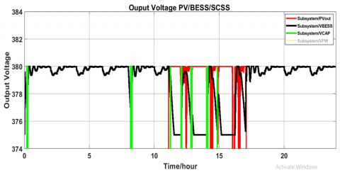
Figure 5. PV/BESS/SCSS output
Figure 6. PV/BESS output
Figure 5 shows the PV/BESS/SCSS, illustrating the power sources exchange between these components during different time intervals, such as from (0:12 to 0:30) minutes, (8:11 to 8:30) as the SCSS response based on BESS drops, and (11:17 to 11:26), showing the relationship between the energy sources as the behavior of PV and BESS fluctuates.
Figure 6 shows the power sources exchange between PV and BESS in time intervals from 11:00 h to 17:00 h. The Figures 4-6 show the response of energy storage systems based on the decrease and increase in PV, as well as on the energy stored in the ESS. All of these sequences are based on the control system.
The implementation of an AHESS system integrating components PV/BESS/SCSS/ FESS has been proposed to address the energy requirements of the Zigen clinic in southern Libya. The primary focus of this system is to ensure cost-effectiveness and reliability, as measured by the metrics NPC, LCOE, LPSP, DT, Q, I, and BESS capacity. To determine the optimal number of PV panels and BESS capacity, MCDM methods were employed based on six criteria and six combinations. Specifically, three intelligent decision-making methods, F-SVNS with LST-MM, TOPSIS, and ARAS, were utilized in MATLAB to assess the various criteria and identify the most efficient solution based on the criteria. The MCDM analysis revealed that the combination of (P4) 30 PV panels and a 60 Ah BESS capacity was considered optimal solution based on the determined criteria. In particular, the results highlighted the PV4 over others, with rankings placing it in the first and second positions across different MCDM methods. Consequently, selecting PV4 with specific conditions was identified as the most suitable choice for the proposed AHESS, offering a favorable LCOE of 0.032 and NPC of 19801$.
Future work is to find the optimal configurations for AHESS, potentially integrating an air compressor storage system with PV, including more criteria, such as technical as well as costs and reliability criteria to determine the optimal configuration of components.
|
Acronyms |
|
|
LPSP |
loss power supply probability |
|
NPC |
net present cost |
|
LCOE |
levelized cost of energy |
|
MCDM |
multi criteria decision maker |
|
F-SVNS |
F- single value neutrosophic logic |
|
LST-MM |
linear scale transformation, max method |
|
TOPSIS |
technique for order preference by similarity to ideal solution |
|
ARAS |
additive ratio assessment |
|
SCSS |
suppercondenser storage system |
|
BESS |
battery energy storage system |
|
FESS |
flywheel energy storage system |
|
EDLC |
electric double-layer capacitor |
|
RC |
replacement cost |
|
PWM |
pulse width modulation |
|
AHESS |
autonomous hybrid energy storage system |
|
GAO |
genetic algorithm optimization |
|
AHP |
analytic hierarchy process |
|
ANP |
analytic network process |
|
RE |
renewable energy |
|
RES |
renewable energy source |
|
PV |
photovoltaic |
|
PWM |
pulse width modulation |
|
ANP |
analytic network process |
|
DEMATEL |
decision-making trial and evaluation laboratory |
|
WT |
wind turbine |
|
HSS |
hydrogen storage system |
|
I |
current |
|
DT |
discharging time |
|
Q |
energy capacity |
|
ESS |
energy storage system |
|
DG |
deasil generator |
|
FC |
fuel cell |
|
SDM |
single diode method |
|
DDM |
double diode methods |
|
UPS |
uninterruptible power supplies |
|
EDLC |
electric double-layer capacitor |
|
O&M |
operation and maintance |
|
ELECTRE |
elimination and choice translating reality |
|
STC |
standard test condition |
|
SoC |
state of charge |
|
HOMER |
hybrid optimization of multiple energy resources |
|
STC |
standard test condition |
|
AC |
alternative current |
|
DC |
direct current |
|
Symbols |
|
|
IL |
Diode current |
|
Io |
Reverse saturation current |
|
a |
Modified ideality current |
|
Rs |
Series resistance |
|
Rsh |
Shunt resistance |
|
C |
Total annualized cost |
|
Plifetime |
Project lifetime |
|
CSC |
Supercapacitor energy capacitance |
|
$W_B$ |
Battery-rated capacity |
|
$P_{ch\ a}$ |
Constant charging power |
|
$Y_{P V-r a t e d}$ |
Rated power |
|
$H_T$ |
Incident solar radiation |
|
$H_S$ |
Constant (1kW/m2 STC) |
|
$K_{PV}$ |
Temperature coefficient |
|
$T_C$ |
PV cell temperature |
|
$T_{ref}$ |
Constant STC (25℃) |
|
$Q(t)$ |
BESS current capacity |
|
$Q_n$ |
BESS nominal capacity |
|
$T_{B_{C h r}}$ |
BESS charging time |
|
$SoC_{i n t i}$ |
Initial SoC |
|
$SoC_{end}$ |
Finished SoC |
|
$P_{Ch\ a }$ |
Constant charging power |
|
$E_{s c}$ |
Energy requirement |
|
$V_{a}$ |
SCSS max. operating voltage |
|
Vb |
SCSS min. operating voltage |
|
C |
Total annualized cost |
|
i |
Real interest rate per annual |
|
Plifetime |
Project lifetime |
|
$V_{P V}$ |
Voltage output |
|
k |
Duty cycle |
|
f |
Switching frequency |
|
L |
Inductance |
|
$x_{i j}$ |
Performance of the Alternative value |
|
$R_{i j}$ |
Beneficial criteria |
|
$R_{i j}^*$ |
Non- beneficial criteria |
|
$A w$ |
Alternative weight |
|
T*max |
Truth max value |
|
I* min |
Indeterminacy min value |
|
F* min |
Falsity min value |
|
$\overline{x_{i j}}$ |
Decision matrix |
|
$\hat{x}_{i j}$ |
Weight of normalized matrix |
|
$S_0$ |
Optimal value |
|
$K_i$ |
Relative efficiency |
|
$w_j$ |
Weight |
|
$x_j^b$ |
Best alternatives of criterion. |
|
$x_j^w$ |
Worst alternatives of criterion. |
|
$d_i^b$ |
Separating distance of $x_j^b$ |
|
$d_i^w$ |
Separating distance of $x_j^w$ |
|
$S_i$ |
Optimal solution |
|
BAIS |
Benefit attribute ideal solution |
|
TS |
Truth-membership function |
|
IS |
Indeterminacy-membership function |
|
FS |
Falsity-membership function |
|
Q1 and Q2 |
Transistor Switches |
|
PL |
Power Load |
|
Pbus |
Power Bus |
|
Vref |
Reference voltage |
|
VBUS |
Bus Voltage |
|
IB |
BESS current |
|
Iref |
Reference current |
|
PI |
Proportional Integration |
|
S1 - Sʹ1 |
BESS bidirectional converter switches |
|
S2 - Sʹ2 |
FESS bidirectional converter switches |
|
S3 - Sʹ3 |
SCSS bidirectional converter switches |
|
Greek symbols |
|
|
Ω |
Ohm |
|
$\omega_{min}$ |
Minimum velocity |
|
$\omega_{max}$ |
Maximum velocity |
|
$\Delta I_L$ |
Ripple current |
|
Ʃ |
Summing |
|
$\alpha_{i j}$ |
Normalize evaluation matrix |
[1] Muchande, S., Thale, S., Wandhare, R. (2020). Integrated solar pv-battery and micro-hydro based low-voltage autonomous dc microgrid for rural electrification. In 2020 47th IEEE Photovoltaic Specialists Conference (PVSC), Calgary, AB, Canada, 2020, pp. 2612-2618. https://doi.org/10.1109/PVSC45281.2020.9300876
[2] Zahedi, R., Ardehali, M.M. (2020). Power management for storage mechanisms including battery, supercapacitor, and hydrogen of autonomous hybrid green power system utilizing multiple optimally-designed fuzzy logic controllers. Energy, 204: 117935. https://doi.org/10.1016/j.energy.2020.117935
[3] Guan, Y., Liu, Z., Du, Y., Xu, D. (2023). Evaluating batteries for renewable energy storage: A hybrid MCDM framework based on combined objective weights and uncertainty-preserved COPRAS. Journal of Renewable and Sustainable Energy, 15(4): 044102. https://doi.org/10.1063/5.0153007
[4] Ren, X., Sun, S., Yuan, R. (2021). A study on selection strategies for battery electric vehicles based on sentiments, analysis, and the MCDM model. Mathematical Problems in Engineering, 2021(1): 9984343. https://doi.org/10.1155/2021/9984343
[5] Ramezanzade, M., Karimi, H., Almutairi, K., Xuan, H.A., Saebi, J., Mostafaeipour, A., Techato, K. (2021). Implementing MCDM techniques for ranking renewable energy projects under fuzzy environment: A case study. Sustainability, 13(22): 12858. https://doi.org/10.3390/su132212858
[6] Thakkar, N., Paliwal, P. (2024). Data driven MCDM models for reliability-economic-environmental analysis of energy storage based autonomous micro-grid. Journal of Energy Storage, 81: 110408. https://doi.org/10.1016/j.est.2023.110408
[7] Goswami, S.S., Mohanty, S.K., Behera, D.K. (2022). Selection of a green renewable energy source in India with the help of MEREC integrated PIV MCDM tool. Materials Today: Proceedings, 52: 1153-1160. https://doi.org/10.1016/j.matpr.2021.11.019
[8] Das, S., De, S. (2023). MCDM for simultaneous optimum economy, investment risk and environmental impact for distributed renewable power: Demonstration with an Indian village data. Energy Conversion and Management, 277: 116631. https://doi.org/10.1016/j.enconman.2022.116631
[9] Chisale, S. W., Lee, H.S. (2023). Evaluation of barriers and solutions to renewable energy acceleration in Malawi, Africa, using AHP and fuzzy TOPSIS approach. Energy for Sustainable Development, 76: 101272. https://doi.org/10.1016/j.esd.2023.101272
[10] Sarkodie, W.O., Ofosu, E.A., Ampimah, B.C. (2022). Decision optimization techniques for evaluating renewable energy resources for power generation in Ghana: MCDM approach. Energy Reports, 8: 13504-13513. https://doi.org/10.1016/j.egyr.2022.10.120
[11] Ecer, F. (2021). A consolidated MCDM framework for performance assessment of battery electric vehicles based on ranking strategies. Renewable and Sustainable Energy Reviews, 143: 110916. https://doi.org/10.1016/j.rser.2021.110916
[12] Pal, P., Mukherjee, V. (2021). Off-grid solar photovoltaic/hydrogen fuel cell system for renewable energy generation: An investigation based on techno-economic feasibility assessment for the application of end-user load demand in North-East India. Renewable and Sustainable Energy Reviews, 149: 111421. https://doi.org/10.1016/j.rser.2021.111421
[13] Ayodele, T.R., Ogunjuyigbe, A.S.O., Oyelowo, N.O. (2020). Hybridisation of battery/flywheel energy storage system to improve ageing of lead-acid batteries in PV-powered applications. International Journal of Sustainable Engineering, 13(5): 337-359. https://doi.org/10.1080/19397038.2020.1725177
[14] Tetuko, R., Lystianingrum, V., Wibowo, R.S. (2022). Optimal scheduling of battery-flywheel hybrid energy storage system for off-grid power system with renewable energy. In 2022 International Conference on Technology and Policy in Energy and Electric Power (ICT-PEP), Jakarta, Indonesia, pp. 220-225. https://doi.org/10.1109/ICT-PEP57242.2022.9988817
[15] Yakub, A.O., Same, N.N., Owolabi, A.B., Nsafon, B.E.K., Suh, D., Huh, J.S. (2022). Optimizing the performance of hybrid renewable energy systems to accelerate a sustainable energy transition in Nigeria: A case study of a rural healthcare centre in Kano. Energy Strategy Reviews, 43: 100906. https://doi.org/10.1016/j.esr.2022.100906
[16] Adeyemo, A.A., Amusan, O.T. (2022). Modelling and multi-objective optimization of hybrid energy storage solution for photovoltaic powered off-grid net zero energy building. Journal of Energy Storage, 55: 105273. https://doi.org/10.1016/j.est.2022.105273
[17] Chennaif, M., Zahboune, H., Elhafyani, M., Zouggar, S. (2021). Electric system cascade extended analysis for optimal sizing of an autonomous hybrid CSP/PV/wind system with battery energy storage system and thermal energy storage. Energy, 227: 120444. https://doi.org/10.1016/j.energy.2021.120444
[18] Rullo, P., Braccia, L., Luppi, P., Zumoffen, D., Feroldi, D. (2019). Integration of sizing and energy management based on economic predictive control for standalone hybrid renewable energy systems. Renewable Energy, 140: 436-451. https://doi.org/10.1016/j.renene.2019.03.074
[19] Saini, P., Gidwani, L. (2020). Optimal siting and sizing of battery in varying PV generation by utilizing genetic algorithm in distribution system. In 2020 21st National Power Systems Conference (NPSC), Gandhinagar, India, pp. 1-6. https://doi.org/10.1109/NPSC49263.2020.9331765
[20] Elmorshedy, M.F., Elkadeem, M.R., Kotb, K.M., Taha, I.B., Mazzeo, D. (2021). Optimal design and energy management of an isolated fully renewable energy system integrating batteries and supercapacitors. Energy Conversion and Management, 245: 114584. https://doi.org/10.1016/j.enconman.2021.114584
[21] Maliro, P., Diarra, B., Samikannu, R. (2022). Technical and economic feasibility assessment for a solar PV mini-grid for Matekenya village. Cogent Engineering, 9(1): 2110707. https://doi.org/10.1080/23311916.2022.2110707
[22] Kang, T., Yao, J., Jin, M., Yang, S., Duong, T. (2018). A novel improved cuckoo search algorithm for parameter estimation of photovoltaic (PV) models. Energies, 11(5): 1060. https://doi.org/10.3390/en11051060
[23] Humada, A.M., Darweesh, S.Y., Mohammed, K.G., et al. (2020). Modeling of PV system and parameter extraction based on experimental data: Review and investigation. Solar Energy, 199: 742-760. https://doi.org/10.1016/j.solener.2020.02.068
[24] Li, C., Zhou, D., Wang, H., Cheng, H., Li, D. (2019). Feasibility assessment of a hybrid PV/diesel/battery power system for a housing estate in the severe cold zone—A case study of Harbin, China. Energy, 185: 671-681. https://doi.org/10.1016/j.energy.2019.07.079
[25] Riaz, A., Sarker, M.R., Saad, M.H.M., Mohamed, R. (2021). Review on comparison of different energy storage technologies used in micro-energy harvesting, WSNs, low-cost microelectronic devices: Challenges and recommendations. Sensors, 21(15): 5041. https://doi.org/10.3390/s21155041
[26] Ramos, A., Tuovinen, M., Ala-Juusela, M. (2021). Battery energy storage system (BESS) as a service in Finland: Business model and regulatory challenges. Journal of Energy Storage, 40: 102720. https://doi.org/10.1016/j.est.2021.102720
[27] Fathima, A.H., Palanisamy, K. (2014). Battery energy storage applications in wind integrated systems—a review. In 2014 International Conference on Smart Electric Grid (ISEG), Guntur, India, pp. 1-8. https://doi.org/10.1109/ISEG.2014.7005604
[28] Chang, W.Y. (2013). The state of charge estimating methods for battery: A review. International Scholarly Research Notices, 2013(1): 953792. https://doi.org/10.1155/2013/953792
[29] Wu, S., Xu, Q., Li, Q., Yuan, X., Chen, B. (2017). An optimal charging strategy for PV-based battery swapping stations in a DC distribution system. International Journal of Photoenergy, 2017(1): 1504857. https://doi.org/10.1155/2017/1504857
[30] Soomro, A., Pullen, K.R., Amiryar, M.E. (2021). Hybrid PV system with high-speed flywheel energy storage for remote residential loads. Clean Technologies, 3(2): 351-376. https://doi.org/10.3390/cleantechnol3020020
[31] Nguyen, X.P., Hoang, A.T. (2020). The flywheel energy storage system: An effective solution to accumulate renewable energy. In 2020 6th International Conference on Advanced Computing and Communication Systems (ICACCS), Coimbatore, India, pp. 1322-1328. https://doi.org/10.1109/ICACCS48705.2020.9074469
[32] Altayf, A.A., Trabelsi, H. (2023). Review of reliability and economically based on wind turbine and photovoltaic with different energy storage systems. In 2023 20th International Multi-Conference on Systems, Signals & Devices (SSD), Mahdia, Tunisia, pp. 89-98. https://doi.org/10.1109/SSD58187.2023.10411257
[33] Arani, A.K., Karami, H., Gharehpetian, G.B., Hejazi, M.S.A. (2017). Review of Flywheel Energy Storage Systems structures and applications in power systems and microgrids. Renewable and Sustainable Energy Reviews, 69: 9-18. https://doi.org/10.1016/j.rser.2016.11.166
[34] Mahlia, T.M.I., Saktisahdan, T. J., Jannifar, A., Hasan, M.H., Matseelar, H.S.C. (2014). A review of available methods and development on energy storage; technology update. Renewable and Sustainable Energy Reviews, 33: 532-545. https://doi.org/10.1016/j.rser.2014.01.068
[35] Olabi, A.G., Wilberforce, T., Abdelkareem, M.A., Ramadan, M. (2021). Critical review of flywheel energy storage system. Energies, 14(8): 2159. https://doi.org/10.3390/en14082159
[36] Amiryar, M.E., Pullen, K.R. (2017). A review of flywheel energy storage system technologies and their applications. Applied Sciences, 7(3): 286. https://doi.org/10.3390/app7030286
[37] Malozyomov, B.V., Martyushev, N.V., Kukartsev, V.A., et al. (2023). Study of supercapacitors built in the start-up system of the main diesel locomotive. Energies, 16(9), 3909. https://doi.org/10.3390/en16093909
[38] Ma, N., Yang, D., Riaz, S., Wang, L., Wang, K. (2023). Aging mechanism and models of supercapacitors: A review. Technologies, 11(2): 38. https://doi.org/10.3390/technologies11020038
[39] Yang, H. (2018, August). A review of supercapacitor-based energy storage systems for microgrid applications. In 2018 IEEE Power & Energy Society General Meeting (PESGM), Portland, OR, USA, pp. 1-5. https://doi.org/10.1109/PESGM.2018.8585956
[40] Salameh, T., Abdelkareem, M.A., Olabi, A.G., Sayed, E.T., Al-Chaderchi, M., Rezk, H. (2021). Integrated standalone hybrid solar PV, fuel cell and diesel generator power system for battery or supercapacitor storage systems in Khorfakkan, United Arab Emirates. International Journal of Hydrogen Energy, 46(8): 6014-6027. https://doi.org/10.1016/j.ijhydene.2020.08.153
[41] Lokesh, V., Badar, A. Q. (2023). Optimal sizing of RES and BESS in networked microgrids based on proportional peer-to-peer and peer-to-grid energy trading. Energy Storage, 5(7): e464. https://doi.org/10.1002/est2.464
[42] Odoi-Yorke, F., Woenagnon, A. (2021). Techno-economic assessment of solar PV/fuel cell hybrid power system for telecom base stations in Ghana. Cogent Engineering, 8(1): 1911285. https://doi.org/10.1080/23311916.2021.1911285
[43] Guertler, M.R., Sick, N. (2021). Exploring the enabling effects of project management for SMEs in adopting open innovation–A framework for partner search and selection in open innovation projects. International Journal of Project Management, 39(2): 102-114. https://doi.org/10.1016/j.ijproman.2020.06.007
[44] Heidary Dahooie, J., Kazimieras Zavadskas, E., Abolhasani, M., Vanaki, A., Turskis, Z. (2018). A novel approach for evaluation of projects using an interval–valued fuzzy additive ratio assessment (ARAS) method: A case study of oil and gas well drilling projects. Symmetry, 10(2): 45. https://doi.org/10.3390/sym10020045
[45] Dhurkari, R.K. (2022). MCDM methods: Practical difficulties and future directions for improvement. RAIRO-Operations Research, 56(4): 2221-2233. https://doi.org/10.1051/ro/2022060
[46] Garcia-Orozco, S., Vargas-Gutierrez, G., Ordonez-Sanchez, S., Silva, R. (2023). Using multi-criteria decision making in quality function deployment for offshore renewable energies. Energies, 16(18): 6533. https://doi.org/10.3390/en16186533
[47] Gribiss, H., Aghelinejad, M.M., Yalaoui, F. (2023). Configuration selection for renewable energy community using MCDM methods. Energies, 16(6): 2632. https://doi.org/10.3390/en16062632
[48] Çolak, M., Kaya, İ. (2017). Prioritization of renewable energy alternatives by using an integrated fuzzy MCDM model: A real case application for Turkey. Renewable and Sustainable Energy Reviews, 80: 840-853. https://doi.org/10.1016/j.rser.2017.05.194
[49] Taherdoost, H., Madanchian, M. (2023). Multi-criteria decision making (MCDM) methods and concepts. Encyclopedia, 3(1): 77-87. https://doi.org/10.3390/encyclopedia3010006
[50] Alanazi, A., Alanazi, M. (2023). Multicriteria decision-making for evaluating solar energy source of Saudi Arabia. Sustainability, 15(13): 10228. https://doi.org/10.3390/su151310228
[51] Wang, C.N., Chung, Y.C., Wibowo, F.D., Dang, T.T., Nguyen, N.A.T. (2023). Site selection of solar power plants using hybrid MCDM models: A case study in Indonesia. Energies, 16(10): 4042. https://doi.org/10.3390/en16104042
[52] Smarandache, F. (1998). Neutrosophy: Neutrosophic probability, set, and logic. Analytic Synthesis & Synthetic Analysis.
[53] Kahraman, C., Otay, İ. (2019). Fuzzy Multi-Criteria Decision-Making Using Neutrosophic Sets. Berlin, Germany: Springer.
[54] Chatterjee, P., Chakraborty, S. (2013). Gear material selection using complex proportional assessment and additive ratio assessment-based approaches: A comparative study. International Journal of Materials Science and Engineering, 1(2): 104-111.
[55] Nguyen, H.T., Md Dawal, S.Z., Nukman, Y., P. Rifai, A., Aoyama, H. (2016). An integrated MCDM model for conveyor equipment evaluation and selection in an FMC based on a fuzzy AHP and fuzzy ARAS in the presence of vagueness. PloS One, 11(4): e0153222. https://doi.org/10.1371/journal.pone.0153222
[56] Ullah, Z., Elkadeem, M.R., Kotb, K.M., Taha, I.B., Wang, S. (2021). Multi-criteria decision-making model for optimal planning of on/off grid hybrid solar, wind, hydro, biomass clean electricity supply. Renewable Energy, 179: 885-910. https://doi.org/10.1016/j.renene.2021.07.063
[57] Emovon, I., Samuel, O.D. (2017). Prioritising alternative solutions to power generation problems using MCDM techniques: Nigeria as case study. International Journal of Integrated Engineering, 9(3): 11-17.
[58] Chien, F., Wang, C.N., Nguyen, V.T., Nguyen, V.T., Chau, K.Y. (2020). An evaluation model of quantitative and qualitative fuzzy multi-criteria decision-making approach for hydroelectric plant location selection. Energies, 13(11): 2783. https://doi.org/10.3390/en13112783
[59] Singh, G., Kundu, S. (2020). An efficient DC-DC boost converter for thermoelectric energy harvesting. AEU-International Journal of Electronics and Communications, 118: 153132. https://doi.org/10.1016/j.aeue.2020.153132
[60] Bendaoud, K., Laassiri, J., Krit, S.D., El Maimouni, L. (2016). Design and simulation DC-DC power converters buck and boost for mobile applications using Matlab/Simulink. In 2016 International Conference on Engineering & MIS (ICEMIS), Agadir, Morocco, pp. 1-6. https://doi.org/10.1109/ICEMIS.2016.7745361
[61] Padhmanabhaiyappan, S., Karthik, R., Ayyar, K. (2018). Investigation of controllers for dc-dc boost converter. In 2018 International Conference on Power, Energy, Control and Transmission Systems (ICPECTS), Chennai, India, pp. 306-308. https://doi.org/10.1109/ICPECTS.2018.8521643
[62] Chub, A., Vinnikov, D., Kosenko, R., Liivik, E., Galkin, I. (2019). Bidirectional DC–DC converter for modular residential battery energy storage systems. IEEE Transactions on Industrial Electronics, 67(3): 1944-1955. https://doi.org/10.1109/TIE.2019.2902828
[63] Alatai, S., Salem, M., Ishak, D., et al. (2021). A review on state-of-the-art power converters: Bidirectional, resonant, multilevel converters and their derivatives. Applied Sciences, 11(21): 10172. https://doi.org/10.3390/app112110172
[64] Albert, J.R., Stonier, A.A. (2020). Design and development of symmetrical super-lift DC-AC converter using firefly algorithm for solar-photovoltaic applications. IET Circuits, Devices & Systems, 14(3): 261-269. https://doi.org/10.1049/iet-cds.2018.5292
[65] Antivachis, M., Anderson, J.A., Bortis, D., Kolar, J.W. (2020). Analysis of a synergetically controlled two-stage three-phase DC/AC buck-boost converter. CPSS Transactions on Power Electronics and Applications, 5(1): 34-53. https://doi.org/10.24295/CPSSTPEA.2020.00004