Youssef Bandeira El Halal![]() | Giulio Lorenzini*
| Giulio Lorenzini*![]() | Giovani Dambros Telli
| Giovani Dambros Telli![]() | Rafael Adriano Alves Camargo Gonçalves
| Rafael Adriano Alves Camargo Gonçalves![]() | Liércio André Isoldi
| Liércio André Isoldi![]() | Luiz Alberto Oliveira Rocha
| Luiz Alberto Oliveira Rocha![]() | Elizaldo Domingues dos Santos
| Elizaldo Domingues dos Santos![]()
© 2025 The authors. This article is published by IIETA and is licensed under the CC BY 4.0 license (http://creativecommons.org/licenses/by/4.0/).
OPEN ACCESS
This study presents a numerical investigation of a steady, two-dimensional, incompressible turbulent flow with forced convection along a small channel with corrugated walls in a trapezoidal shape. The objective of this study is to evaluate the effect of corrugation geometry on the heat transfer rate and pressure drop through the channel. The constructal design method was applied to the geometry domain with two constraints: the total area of the channel and the area of the trapezoidal corrugation upstream of the channel. Two degrees of freedom are considered: the ratio of the smaller base to the larger base of the upstream trapezoidal corrugation (LA2/LA1) and the ratio of the trapezoid’s height to its larger base (H1/LA1). All cases were simulated for convective flows with Reynolds and Prandtl numbers of ReD = 22,000 and Pr = 0.71, respectively. The time-averaged mass, momentum, and energy conservation equations are solved using the Finite Volume Method with the RANS (Reynolds-Averaged Navier-Stokes) turbulence model and the k-ω SST (Shear Stress Transport) turbulence closure model. The results indicate that a specific H1/LA1 ratio improves the heat transfer rate by 26.2% compared to the worst case for the same LA2/LA1 ratio. Furthermore, larger insertions of trapezoidal corrugations at the bottom of the channel enhance the thermal performance of the heat exchanger, while the insertion of corrugations at the upper part of the channel has a negligible effect on heat transfer performance. From a fluid dynamic perspective, smaller insertions in the fluid flow direction led to lower pressure losses.
corrugation, small channel, forced convection, constructal design, heat exchanger, turbulent flow
Currently, the growing global demand for energy has become a serious issue. It is driven primarily by population growth and increasing basic needs [1]. Projections indicate that energy consumption might increase by approximately 50% to 2050, followed by a significant rise in carbon dioxide emissions [2]. Only the energy used in the industry sector is responsible for around 24.2% of the greenhouse gases [3]. In this context, one of the key missions of the engineering field is to reduce greenhouse gases emissions by finding more efficient ways to utilize energy, both in the production of goods and in daily life.
Among the most commonly used equipment in industry are heat exchangers. These devices need an electrical energy supply from a compressor or other mechanical work (such as fans or pumps) to drive the fluid, thereby removing or adding thermal energy to a system. The development of heat recovery systems is completely linked to improving the energy efficiency of a variety of processes and systems in the industry or even in other sectors [4]. In this context, improving the heat transfer and reducing energy loss within the channels through which the fluid flows are essential to increase the energy efficiency of systems.
In the literature, there are numerous studies focusing on optimizing heat exchangers to enhance their efficiency [5-7]. However, there is a need to reduce their size to develop effective cooling solutions for new technologies, such as microelectronics systems. In this regard, microchannel heat exchangers have emerged as an interesting solution. This type of heat exchange has the advantage of their high heat removal potential due to a larger specific surface area combined with small size [8]. They can be applied to several applications such as refrigeration systems [9], membrane-based heat exchangers [10], supercritical carbon dioxide (sCO2) Brayton cycles [11], electronic systems [12] and solar panels [13]. Although microchannel heat exchangers are not a new technology, there are relatively few studies addressing their heat transfer and hydraulic performance in relation to their design. Some research focuses on manufacturing techniques for micro heat exchangers [14-16], and the influence of materials used in their fabrication [17, 18].
Tuckerman and Pease [19] were the first to study and introduce the concept of microchannel heat exchangers for electronic microcircuits. They observed that the convective heat transfer coefficient (h) is inversely proportional to the channel width. After this work, Peiyi and Little [20] investigated the friction coefficient and pressure drop in microchannels with trapezoidal cross-sections made of silicon. Then, Peng et al. [21] experimentally studied the forced convection heat transfer in microchannels with rectangular cross-sections. The authors observed that the flow became fully turbulent at Reynolds numbers starting from 1500, and the transition from laminar to turbulent flow occurred within the range of 200 to 700 in the microchannels.
More recently, Wang et al. [22] conducted both experimental and numerical studies on a micro heat exchanger with a trapezoidal cross-section in laminar flow. Based on their findings, the authors concluded that the Navier-Stokes and energy equations can be effectively used to predict the physical behavior of fluids in microchannels. Yu et al. [23] investigated the thermal and fluid dynamic characteristics in tree-shaped microchannels for various geometric ratios in laminar flow, employing the fractal method. The authors observed that, due to the formation of vortices in microchannels with this geometry, heat transfer was enhanced compared to straight microchannels of the same cross-sectional area.
Chai et al. [24] investigated the effects of fan-shaped insertions in a rectangular microchannel on the temperature field and the local and average heat transfer under laminar flow conditions. The authors analyzed two main configurations: the first with alternating insertions on the lower and upper walls of the domain, and the second with aligned insertions. Additionally, they examined the influence of geometric variations of the ribs. The authors observed that the channel height and the spacing between insertions have a significant influence on heat transfer. For microchannels with smaller heights and larger spacing between insertions, the aligned configuration showed better heat transfer performance.
Pan et al. [25] compared a conventional rectangular microchannel heat exchanger to one with fan-shaped cavities under laminar flow. The results demonstrated that the heat exchanger with fan-shaped cavities showed higher heat transfer performance and reduced pressure drop compared to the conventional design. In the study of Hou and Xu [8], five microchannel heat exchangers with elliptical concave cavities were designed to investigate the pressure drop and heat transfer performance. Results show that as the ellipticity increases, the pressure drop decreases, reaching a minimum at ellipticity 1.0. At this point, it was also found to have the best heat transfer performance.
From the literature, it is clear that the heat exchanger’s thermal and hydraulic performance is largely determined by its geometric design and fluid flow characteristics [1]. The heat exchanger design – cross section, fin geometry, positions and number of rows – can modify the flow patterns, affecting boundary layers and their attachment/reattachment, making it easier or harder to transfer heat and influencing the overall heat transfer performance. In this regard, the constructal design can help to identify flow architectures that improve the systems’ efficiency. This methodology originated from the Constructal Law, which outlines the natural tendency of any flow system to evolve over time in order to facilitate access to the internal streams running through it [26-28]. The change in design is made to minimize the system’s thermodynamic imperfections [29, 30]. The constructal design approach is widely used in heat transfer applications, such as in fins, cavities and channels [31-34], radiant cooling panels [35], heat exchangers [36-39] or even in battery cooling systems [40-42]. From these examples, changing the flow architectures by the constructal design lenses helps to improve the system’s efficiency.
In this context, this work analyzes the corrugation geometry in a small channel that simulates microchannel heat exchanger under turbulent flow and forced convection in order to enhance the heat transfer performance and reduce the pressure losses. The main contribution of this work lies in applying the constructal design to investigate corrugation geometry in microchannels under turbulent forced convection—a topic scarcely explored in the literature. The objective is to propose theoretical design guidelines that minimize pressure drop and energy losses while maximizing heat transfer efficiency and then, offering new insights into the influence of geometric parameters on the thermal-hydraulic performance of microchannel heat exchangers.
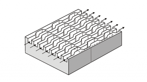
This study investigates turbulent flow through a channel that mimics a microchannel heat exchanger, as illustrated in Figure 1. The system consists of a channel with a height of H = 10 mm and a length of L = 50 mm, and trapezoidal corrugated walls. Air is defined as the working fluid, which enters the microchannels with an inlet velocity of 14.6 m/s (ReH = 22,000), with a Prandtl number of 0.71, and an inlet temperature of Tin = 300 K, which approximates to ambient conditions. The air’s thermal-physical properties are defined as ρ = 1.225 kg/m³, Cp = 1006.43 J/kgK, k = 0.0242 W/mK and μ = 1.7894x10⁻⁵ kg/ms. The fluid flows along the channel toward the outlet, where a boundary condition of gauge pressure Pgauge = 0 Pa is applied.
Figure 1. Illustration of heat exchanger with corrugated-wall microchannels
For the thermal field, a locally parabolic condition (∂T/∂n = 0) is imposed at the outlet, where n denotes the flow direction in the control volume immediately upstream of the channel exit. This approach prevents non-physical solutions that may arise from vortex formation at the domain boundary. The channel walls are maintained at a constant temperature of Tw = 330 K, representing a typical operating temperature of electronic components. The difference between the wall and air flow temperature provides the temperature gradient that drives the heat transfer within the system.
Regarding the fluid flow boundary conditions, the no-slip condition and impermeability constraints (u = v = 0 m/s) are applied to the top and bottom surfaces of the channel. Figure 2 shows the computational domain and boundary conditions (a), and also the channel dimensions (b).
Since the objective of this study is to analyze the influence of the channel corrugation geometry on both the heat transfer rate and pressure drop, Figure 2b illustrates the computational domain and the evaluated geometric parameters, where H1 represents the corrugation height, LA1 is the larger base of the trapezoid, and LA2 is the smaller base.
The geometric evaluation was conducted using the Constructal Design method [26, 43]. Figure 3 presents the flowchart steps to apply the constructal design methodology. Steps 1 and 2 are the definition of the flow system and what is flowing, respectively. As presented before, the system in analysis is the channel heat exchanger under forced convection and turbulent flow, and what is flowing is the heat transfer from the channel walls to the air flowing.
Steps 3 to 5 of Figure 3 are presented in this paragraph. In this work, specific constraints are applied to investigate the effect of certain geometric ratios on two performance indicators: the heat transfer rate, which is to be maximized, and the pressure drop, which is to be minimized. A geometric constraint is imposed on the trapezoidal area, which represents the channel corrugation, set as the total area of AT = 11.25 mm², considering the limitations imposed by the channel width. Based on this constraint, two degrees of freedom are defined and studied: H1/LA1 (the ratio of trapezoid height to larger base) and LA2/LA1 (the ratio of the smaller base to the larger base of the trapezoid). It is important to highlight that these ratios were applied to the upstream corrugations, while the downstream corrugations are kept constant.
The design of the simulations, step 6, was organized as follows: Initially, H1/LA1 is held constant, and various LA2/LA1 ratios are analyzed, as presented in Table 1. This process leads to the definition of the optimal value of (LA2/LA1)o. Additionally, the corresponding maximized heat transfer rate per unit depth (q′m) and minimized pressure drop (ΔPm) are determined. It is worth noting that, for the optimal ratios, it is used a subscript “F” for the configurations that minimize the pressure drop, and the subscript “T” for the cases that maximize the heat transfer rate. The next step involves varying H1/LA1 and performing simulations for each value using the same LA2/LA1 ratios evaluated previously. The configurations that conduct to the twice-maximized heat transfer rate (q′mm), and the twice-minimized pressure drop (ΔPmm) are the twice-optimized ratio (LA₂/LA₁)oo, and the once-optimized ratio (H1/LA1)o. The studied H1/LA1 ratios are also listed in Table 1. Figure 4 provides a schematic overview of the simulation process followed in this study.
To perform the simulations to find the best system design (step 7), numerical solutions of governing equations were adopted. Subsequently, the impacts of the H1/LA1 on both heat transfer rate and pressure drop are analyzed. Then, if it is not possible to add more freedom to the system, the design is completed since the best design was found for the constraints and degree of freedom adopted for this work. In this work, step 8 was not implemented, but it can be applied in future works if new opportunities to improve the system performance are identified.
Figure 2. Computational domain of the corrugated channel
Figure 3. Constructal design method flowchart steps. Adapted from [40, 44]
Table 1. Simulated values for each degree of freedom
|
Search Range |
||||||||||
|
H1/LA1 |
0.05 |
0.10 |
0.15 |
0.20 |
0.25 |
0.30 |
- |
- |
- |
- |
|
LA2/LA1 |
0.10 |
0.20 |
0.30 |
0.40 |
0.50 |
0.60 |
0.70 |
0.80 |
0.90 |
1.00 |
Figure 4. Simulation flowchart illustrating the cases investigated in the present study
The problem under study in this work involves a two-dimensional, turbulent, steady-state flow with heat transfer by forced convection. The conservation equations for mass, momentum in the x and y directions, and energy are given, respectively, by [45]:
∂ˉu∂x+∂ˉv∂y=0 (1)
∂∂x(ρˉuˉu)+∂∂y(ρˉvˉu)=−∂P∂x+(μ+μt)(∂2ˉu∂x2+∂2ˉu∂y2) (2)
∂∂x(ρˉuˉv)+∂∂y(ρˉvˉv)=−∂P∂y+(μ+μt)(∂2ˉv∂x2+∂2ˉv∂y2) (3)
∂∂x(ˉuˉT)+∂∂y(ˉvˉT)=(α+αt)(∂2ˉT∂x2+∂2ˉT∂y2) (4)
where, ρ is the fluid density [kg/m³], u and v are the fluid velocity components in the x and y directions, respectively [m/s], k is the thermal conductivity of the fluid [W/m·K], cₚ is the specific heat of the fluid [J/kg·K], μ denotes the dynamic viscosity of the fluid [N·s/m²], T is the fluid temperature [K], and P represents the fluid pressure. The overbar placed above the temperature and velocity variables indicate time-averaging. To address the turbulence closure problem, the k-ω SST model was selected. This model consists of two equations and is highly adaptive since it employs the k-ω formulation in the inner region of the boundary layer while transitioning to the k-ε model in the free stream, thereby avoiding the sensitivity issues inherent to the original model in these regions [46, 47]. More details about the modeling can be seen in the Refs. [46-48].
The governing equations, Eqs. (1-4), are solved using Ansys Fluent [49, 50]. The software applies the finite volume method to solve the equations. The turbulence model employed is the k-ω SST model, using the default parameter settings provided by the software. For the pressure-velocity coupling, the SIMPLE-C algorithm (Semi-Implicit Method for Pressure Linked Equations-Consistent) is applied. A pressure-based solver is used, and the simulation is conducted under steady-state conditions. Given the significant influence of convective transport in the present problem, a second-order Upwind interpolation scheme is used for the discretization of the momentum, energy, and specific dissipation rate equations. For the turbulent kinetic energy equation, a first-order Upwind scheme is employed, as the flow exhibits abrupt variations within the domain, and this scheme is better suited to handle such discontinuities while minimizing numerical errors. Standard under-relaxation factors from Ansys Fluent were used. The simulations converged when at least two consecutive iterations were less than 10−6 for mass equation, 10−6 for momentum equation, 10−8 for the energy equation, 10−6 for turbulent kinetic energy and 10−6 for the specific dissipation rate.
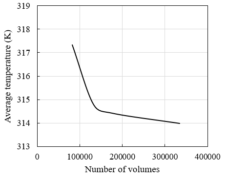
The mesh generation was carried out using the software Ansys Fluent Meshing. To better capture the anisotropic characteristics of the flow, a triangular mesh was used in the central region of the domain. In contrast, near-wall regions were refined with a rectangular mesh to more accurately solve the temperature and velocity gradients in these areas. It is also noticeable that the central region contains coarser volumes; this strategy was employed to reduce the total number of control volumes and, consequently, minimize computational effort. A mesh independence test was conducted for the domain considered in this study. Discretization with approximately 80,000, 130,000, 240,000, and 320,000 control volumes were simulated. The verified variable was the average temperature (Tavg) of the fluid at the outlet of the corrugated channel. Figure 5 shows the mesh independence test results. Analyzing the results, a difference of 3 K in the average temperature is observed between the cases with 80,000 and 130,000 volumes, whereas the difference between 130,000 and 240,000 volumes reduces to just 0.5 K, indicating a region where the temperature field becomes insensitive to further mesh refinement. For this reason, and to avoid unnecessary computational effort, the mesh with 130,000 control volumes was selected for the simulations. It is important to highlight that, for the mesh independence test, all cases were run under transient conditions with a time step of 0.001 seconds and a final simulation time of 5 seconds.
To check the steady-state assumption to reduce computational effort, a comparison between transient and steady-state models was performed. For this analysis, the computational domain with 130,000 control volumes was employed. The convective heat transfer coefficient along the lower wall of the microchannel was verified. In the transient simulations, a time step of 0.001s was adopted. Figure 6 shows the comparison between the steady-state and transient models. The figure demonstrates that there are no significant differences in the convective heat transfer coefficients obtained from the steady-state and transient simulations when comparing the time-averaged fields over the interval of 5.0s. Based on these findings, the steady-state approach was selected for the simulation in this study, ensuring reliable results while substantially decreasing computational cost. It is worth highlighting that, by using the steady-state regime, the total simulation time was reduced from approximately 24 hours to 30 minutes without compromising accuracy.
Figure 5. Mesh independence test under transient conditions for the case studied in the present work
Figure 6. Comparison between the convective heat transfer coefficients obtained using steady-state and transient modeling
Figure 7. Comparison between the convective heat transfer coefficients obtained in the present study and those reported by Teixeira et al. [48] for a flow at ReD = 22,000 and Pr = 0.71
To validate the computational model, the benchmark case presented by Teixeira et al. [48] was employed. The authors’ model was validated based on the works of Ranjan and Dewan [51] and Chen and Xia [52]. The study by Teixeira et al. [48] was chosen for verification because it employs the same Reynolds and Prandtl numbers as used in the present work. Moreover, it also simulates a free shear flow, exhibiting boundary layer separation and reattachment phenomena similar to those induced by the corrugations studied in the present work. Therefore, if the code is successfully verified against this case, it can be assumed to be capable of accurately performing the simulations required in this study. For comparison purposes, the convective heat transfer coefficient (h) was monitored on the faces of the square bluff body. Regarding the computational domain, it consists of a two-dimensional rectangular domain with a length of L = 26D, a height of H = 10D, and a square bluff body side length of D = 1 m. For more detailed information about the discretization used for model verification can be found in the study [48].
Figure 7 presents a comparison between the convective heat transfer coefficient curves obtained in the present study and the results reported by Teixeira et al. [48]. To quantitatively compare the results, the mean relative error was calculated. It can be observed that both curves exhibit very similar behavior, with a mean relative error of 8%, which is considered an acceptable deviation given the simulation of turbulent flows with convection. This error is likely attributed to differences in the mesh discretization between the domain used by the authors and the one employed in this study. Nevertheless, a refined mesh ensuring y⁺ < 1 in the region near the bluff body is maintained.
4.1 Effect of the corrugation geometry on the velocity, pressure and temperature fields
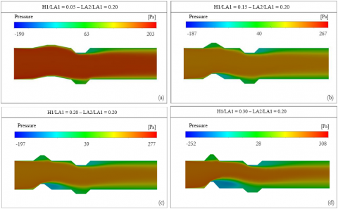
To better understand the physical phenomena inside the channel, it is important to analyze the fluid flow dynamics and how it can impact the temperature field and pressure drop in the microchannel. In this regard, Figures 8, 9 and 10 present the velocity vectors, pressure drop and temperature map for a fixed ratio of LA2/LA1 = 0.20 and different values of H1/LA1, respectively. It is possible to see that by increasing the H1/LA1 ratio, the height of the trapezoid in the bottom part of the channel increases, causing a flow restriction, along with an increase in fluid velocity, particularly in the central region of the channel. In addition, when the H1/LA1 increase, it leads to the formation of recirculation zones, as well as an extended reattachment path for the fluid. For H1/LA1 = 0.05 and H1/LA1 = 0.15, the flow reattachment occurs upstream of the downstream corrugation, while for higher H1/LA1 ratios, reattachment occurs within the following corrugation itself. This behavior contributes to an increase in pressure drop, as observed in Figure 9. It is clear that the corrugation in the bottom part of the channel directly increases the pressure drop since it restricts the fluid flow. However, since heat exchangers typically consist of multiple shared channels, it becomes impractical to remove this corrugation by directing the insertion outward from the domain. This is because the wall of one channel is shared with the adjacent channel, and so on. Consequently, an outward-directed insertion in one channel results in an inward-directed insertion in the neighboring channel.
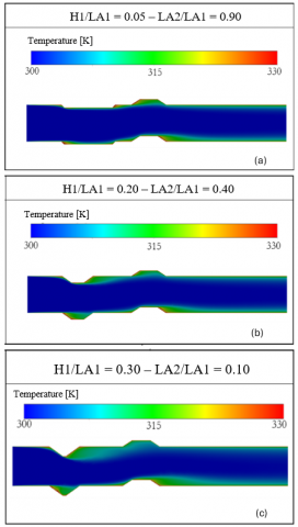
Regarding the fluid temperature in Figure 10, the first key point to highlight is that the corrugations directed outward from the domain are not significant to the temperature map, as they do not significantly affect the temperature fields downstream of the fluid flow. In contrast, the corrugations extending into the channel domain have a considerable influence on the temperature fields, notably impacting the temperature gradients immediately downstream of each corrugation. It is also clear that the temperature gradient increases as the corrugation height increases, with 0.05 < H1/LA1 < 0.30, as illustrated in Figure 10. The results also suggest that applying corrugations with different H1/LA1 ratios - asymmetric corrugations - may lead to improved thermal performance.
4.2 Influence of geometry on heat transfer performance
After presenting the fluid flow and qualitatively understanding the influence of the corrugation geometry on the fluid dynamics and thermal field in the channel, it is also possible to quantitatively assess the impact of the corrugated geometry on the heat transfer rate per unit depth (q'). The interest in this analysis is evaluating how the heat transfer rate responds to variations in the LA2/LA1 and H1/LA1 ratios.
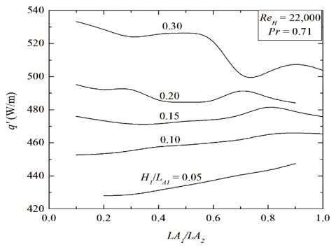
Figure 11 illustrates the heat transfer rate (q') in relation to the LA2/LA1 ratios for the different H1/LA1 ratios. It is interesting to observe the increase in the heat transfer rate (q') with the increasing H1/LA1 ratio. For LA2/LA1 = 0.2, an increase of approximately 26.2% in the heat transfer rate is observed when increasing the H1/LA1 ratio. In contrast, for LA2/LA1 = 0.9, a minor increase of around 14.6% in q’ with an increase in the H1/LA1 ratio was observed. A possible explanation for this trend is the stronger influence of the corrugation height on the interaction between the fluid flow and the heated wall, compared to the effect of corrugation width.
Figure 8. Velocity field for fixed LA2/LA1 = 0.20 ratio and different H1/LA1: (a) H1/LA1 = 0.05, (b) H1/LA1 = 0.15, (c) H1/LA1 = 0.20, (d) H1/LA1 = 0.30
Figure 9. Pressure field for fixed LA2/LA1 = 0.20 ratio and different H1/LA1: (a) H1/LA1 = 0.05, (b) H1/LA1 = 0.15, (c) H1/LA1 = 0.20, (d) H1/LA1 = 0.30
Figure 10. Temperature maps for fixed LA2/LA1 = 0.20 ratio and different H1/LA1: (a) H1/LA1 = 0.05, (b) H1/LA1 = 0.15, (c) H1/LA1 = 0.20, (d) H1/LA1 = 0.30
It can be also seen in Figure 11 that for 0.05 ≤ H1/LA1 ≤ 0.10, the heat transfer rate increases as LA2/LA1 increases. However, when H1/LA1 ≥ 0.15, the behavior of the heat transfer rate presents a different trend, suggesting that the effect of LA2/LA1 is strongly dependent on the value of H1/LA1 ratios. Specifically, at H1/LA1 = 0.15, the heat transfer rate remains nearly constant. Beyond H1/LA1 = 0.20 values, the heat transfer rate shows the opposite trend, meaning that increasing LA2/LA1 ratios results in a decrease in the heat transfer rate. This behavior can be possibly explained by the fact that, for H1/LA1 ≥ 0.15, the LA2/LA1 ratio varying from 0.10 to 1.0 corresponds to a transition in the corrugation geometry from an almost triangular shape to a rectangular one. As a result, at LA2/LA1 = 0.10, the geometry generates fewer recirculation zones and facilitates the interaction between the fluid and the heated walls. Consequently, configurations with higher H1/LA1 and lower LA2/LA1 ratios are able to remove more heat from the walls and exhibit a higher heat transfer rate compared to cases with higher LA2/LA1 values, which have a stronger impact on the fluid flow and lead to reduced heat transfer efficiency. On the other hand, for 0.05 ≤ H1/LA1 ≤ 0.10 values, the increase in the heat transfer rate with the increase in LA2/LA1 can be attributed to the higher fluid flow interaction with the heated wall for higher LA2/LA1 values. To better understand these phenomena, Figure 12 illustrates the temperature map for the cases of H1/LA1 = 0.30 and H1/LA1 = 0.05, respectively. It can be seen that for the H1/LA1 = 0.30 ratio, increasing the LA2/LA1 ratio reduces the temperature gradient immediately downstream of the corrugation. On the other hand, for H1/LA1= 0.05, the temperature gradient increases as LA2/LA1increases.
These findings are particularly relevant to designing and manufacturing this type of heat exchanger. If the manufacture constraints limit the corrugation height to H1/LA1< 0.15, increasing LA2/LA1would be advantageous for maximizing heat transfer. Conversely, if the constraint requires constructing the channel with H1/LA1> 0.15, a lower LA2/LA1ratio should be selected to increase thermal performance.
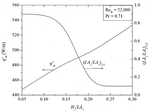
The maximum heat transfer rates (q'm) achieved for each H1/LA1 ratio and their corresponding thermally optimal geometries, denoted as (LA2/LA1)o,T, are summarized in Figure 13. In other words, Figure 13 shows the effect of the H1/LA1 ratio on both the once maximized heat transfer rate (q'm) and the once optimal (LA2/LA1)o,T (on the thermal perspective). The left vertical axis presents the q'm as a function of H1/LA1 (horizontal axis), and it is evident that higher H1/LA1 ratios lead to higher q'm values. The right vertical axis presents the optimal LA2/LA1 ratios corresponding to each q'm. From this figure, it can be seen that the trend inversion previously discussed is noticeable, with a clear change occurring at H1/LA1 = 0.15. Moreover, these results highlight that for lower H1/LA1 ratios, a corrugation shape approaching a rectangle type achieves higher thermal performance. On the other hand, at higher H1/LA1 ratios, the optimal geometry tends to be triangular or a trapezoid with a smaller upper base.
Figure 11. Variation of the heat transfer rate (q’) with H1/LA1 and LA1/LA2 ratios
Figure 12. Microchannel temperature map for different H1/LA1 and LA2/LA2 ratios. Left-side: H1/LA1 = 0.30 and LA2/LA1 – 0.10 (a), 0.60 (b) and 1.0 (c). Right-side: H1/LA1 = 0.05 and LA2/LA1 – 0.30 (d), 0.60 (e) and 0.9
Figure 13. Effect of H1/LA1 on the once maximized heat transfer rate per unit depth (q′m) and the corresponding optimal ratio (LA2/LA1)o,T
Figure 14. Temperature map for selected H1/LA1 ratios and their respective thermally optimal (LA2/LA1)o,T ratios
It is also interesting to note that while the width of the corrugations influences the heat transfer, its effect is less pronounced compared to the corrugation height. The maximum variation in q' as a function of LA2/LA1 for H1/LA1 = 0.05 is only 3.8%, whereas for H1/LA1 = 0.30, the maximum variation is about 4.6%. This trend result collaborates with the findings of Chai et al. [24], who reported a minor influence of width on heat transfer performance for fan-shaped corrugations. Figure 14 illustrates the temperature map for selected H1/LA1 ratios and their respective thermally optimal (LA2/LA1)o,T ratios. Notably, the case with H1/LA1 = 0.30 and LA2/LA1 = 0.10 presents the higher temperature gradient. Consequently, the highest heat transfer rate among the cases investigated in this study. It can be explained by stronger interaction between the corrugations and turbulent flow. The turbulent flow reattachment occurs latter in the microchannel, increasing the intensity and removing more heat.
4.3 Influence of geometry on pressure drop
Figure 15 presents the pressure drop (ΔP) in relation to LA1/LA2 and different H1/LA1 ratios. It is evident from the figure that the pressure drop exhibits higher variability, and it follows a similar trend to the heat transfer rate curves presented in Figure 11. This trend is expected since the corrugations in the microchannel restrict the fluid flow, resulting in an increase in pressure drop. It is evident in Figure 15 that higher H1/LA1 ratios achieved higher pressure drop values. It is because higher H1/LA1 ratios have higher corrugation heights, which restrict more the flow in comparison to lower H1/LA1 ratios. The pressure drop decreases as the LA1/LA2 increases for the H1/LA1 = 0.30. It can also be attributed to the transition in the corrugation geometry from an almost triangular shape to a rectangular one from 0.1 to 1.0 in LA1/LA2 ratios. On the other hand, for lower H1/LA1 values, the pressure drop increases as the LA1/LA2 ratio increases due to the higher fluid flow restriction for higher LA1/LA2 values.
Figure 15. Pressure drop in relation to LA1/LA2 ratios for different H1/LA1 ratios
From an engineering perspective, for a single channel, this pressure differential is not particularly significant, with a maximum difference of only 80 Pa, comparing the pressure drop between H1/LA1 = 0.05 with LA2/LA1 = 0.20 and H1/LA1 = 0.30 with LA2/LA1 = 0.10. Such a pressure difference can be easily compensated for using standard fans and may not represent a limitation in terms of economic feasibility.
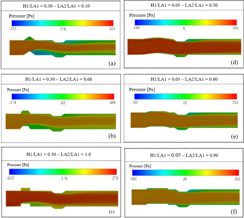
Figure 16. Pressure drop for different H1/LA1 and LA2/LA2 ratios. Left-side: H1/LA1 = 0.30 and LA2/LA1 – 0.10 (a), 0.60 (b) and 1.0 (c). Right-side: H1/LA1 = 0.05 and LA2/LA1 – 0.30 (d), 0.60 (e) and 0.9 (f)
Figure 17. Minimum pressure drop (ΔPmin) for each H1/LA1 (left-side axis) and the optimized (LA2/LA1)o,F ratio for each H1/LA1 (right-side)
Figure 16 presents the pressure map for H1/LA1 = 0.30 at LA2/LA1 = 0.10 (a), LA2/LA1 = 0.60 (b), and LA2/LA1 = 1.00 (c) ratios, respectively. From Figure 16, it is clear that higher pressure gradients occur at higher H1/LA1 with lower LA2/LA1 ratios, and these gradients decrease as LA2/LA1 increases. In addition, it is possible to note that the corrugation that is outward-directed (upper surface of the channel) has a slight effect on the pressure field, while the corrugation inward-directed (bottom surface) to the channel has a strong effect on the pressure field due to its restriction and interaction with the turbulent flow. In the H1/LA1 = 0.30 with LA2/LA1 = 0.10 ratio case, we can see that the corrugation presented almost a triangular shape and has a strong effect in the fluid flow in relation to the cases with LA2/LA1 = 0.60 and 1.0. Similarly, Figure 16 shows the pressure fields for H1/LA1 = 0.05 at LA2/LA1 = 0.20 (d), LA2/LA1 = 0.60 (e), and LA2/LA1 = 0.90 (f). In contrast to the previous case, here the pressure gradients increase with increasing LA2/LA1 ratios. It can be possibly explained by the fact that with H1/LA1 = 0.05, the fluid flow is less restricted than with H1/LA1 = 0.30, meaning that the impact of the LA2/LA1 ratio in the pressure gradient is higher in these cases.
Figure 17 shows the minimum pressure drop (ΔPmin) for each H1/LA1 (left-side axis) and the once optimized (LA2/LA1)o,F ratio (from fluid perspective) for each H1/LA1 (right-side). Although the width of the corrugation has little influence on heat transfer, it plays a more significant role in the pressure drop. Specifically, variations in ΔP as a function of LA2/LA1 reach 19.5% for H1/LA1 = 0.05 and 20.6% for H1/LA1 = 0.30. Therefore, to minimize pressure losses, it is better to use lower LA2/LA1 ratios for smaller insertions and higher LA2/LA1 ratios for larger insertions. This trend is clearly illustrated in Figure 17, where the optimal (LA2/LA1)o,F values are lower for smaller H1/LA1 ratios. It can also be seen that the pressure drop tends to increase with the augmentation of H1/LA1 ratios.
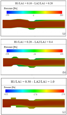
Figure 18 presents the pressure fields for selected H1/LA1 ratios and their corresponding optimized (LA2/LA1)o,F ratios in the flow perspective. The case with H1/LA1 = 0.30 and LA2/LA1 = 1.00 exhibits the highest-pressure gradient. Consequently, there is a higher pressure drop along the channel. On the other hand, the case with H1/LA1 = 0.10 and LA2/LA1 = 0.20 shows the lowest pressure gradient, resulting in the lowest pressure drop.
Figure 18. Pressure fields for selected H1/LA1 ratios and their corresponding optimized (LA2/LA1)o,F ratios in the fluid dynamic perspective. (a) H1/LA1 = 0.10 – (LA2/LA1)o,F = 0.20 (b) H1/LA1 = 0.20 – (LA2/LA1)o,F = 0.40 (c) H1/LA1 = 0.30 – (LA2/LA1)o,F = 1.00
This study investigated, through the application of constructal design method, the effect of different geometric configurations on the heat transfer rate per unit depth and pressure drop in a channel with trapezoidal corrugations under turbulent flow with forced convection. It is important to highlight that this research topic has been scarcely addressed in the literature, especially using the constructal design method to help find the best corrugation designs. The geometric ratios analyzed were H1/LA1, varying from 0.05 to 0.30, and LA2/LA1, ranging from 0.1 to 1.0. The results led to the following conclusions:
From a thermal perspective:
• The H1/LA1 ratio has a greater influence on the heat transfer rate, resulting in a 26.2% increase for LA2/LA1 = 0.1 ratio when comparing H1/LA1 = 0.05 and H1/LA1 = 0.30 ratio. It can be explained by the fact that the corrugation height has a more significant effect than the corrugations widths in the heat transfer.
• Overall, the results demonstrated that the effect of the LA2/LA1 ratio on q' depends on the H1/LA1 ratio. In other words, there is no universal optimal geometry.
• To maximize heat transfer performance when no design constraints are present, increasing H1/LA1 and minimizing LA2/LA1 results in better thermal performance. On the other hand, considering design limitations for a corrugated channel, for small insertions, it is preferable to prioritize increasing the LA2/LA1 ratio.
• The geometric investigation results, combined with the temperature fields, suggest that using asymmetric corrugations on the top and bottom walls may be beneficial since the upper corrugation tends to contribute less to heat transfer.
From a fluid dynamic perspective:
• Increasing the corrugation height through a higher H1/LA1 ratio leads to an increase in pressure drop along the channel. Although the LA2/LA1 ratio has a minimal influence on heat transfer, it significantly affects pressure drop, with variations of 19.5% for H1/LA1 = 0.05 and 20.6% for H1/LA1 = 0.30.
• To minimize pressure drop, lower LA2/LA1 ratios should be used for small insertions and higher ratios for larger insertions.
• The maximum difference in pressure drop observed during the optimization process was only 80 Pa (between H1/LA1 = 0.05, LA2/LA1 = 0.10 and H1/LA1 = 0.30, LA2/LA1 = 0.10). While this may not be significant from an economic point of view for a single channel, it may become relevant depending on the total number of channels in the heat exchanger.
The author G.D. Telli thanks FAPERGS for the financial support (Process: 23/2551-0000802-5). The authors L.A. Isoldi, L.A.O. Rocha, and E.D. dos Santos thank CNPq (Brasília, DF, Brazil) for research grants (Processes: 309648/2021-1, 307791/2019-0, 308396/2021-9). The authors also thank the financial support of CNPq in the Call CNPq/MCTI Nº 10/2023 - Universal (Process: 403408/2023-7). Authors L.A.O. Rocha and E.D. dos Santos thank Fundação para a Ciência e Tecnologia, I.P. (doi.org/10.54499/UIDP/04683/2020; doi.org/10.54499/UIDB/04683/2020).
|
At |
Trapezoidal area |
m2 |
|
cp |
Specific heat at constant pressure |
J/(kg×K) |
|
h |
Convection heat transfer coefficient |
W/(m²×K) |
|
H |
Channel height |
m |
|
H1 |
Height of the trapezoid |
m |
|
k |
Thermal conductivity of the fluid |
W/(m×K) |
|
L |
Channel length |
m |
|
LA1 |
Larger base of the trapezoid |
m |
|
LA2 |
Lower base of the trapezoid |
m |
|
Pgauge |
Pressure |
Pa |
|
Pr |
Prandtl number |
|
|
ReH |
Reynolds number |
|
|
q' |
Heat transfer rate per unit depth |
W/m |
|
T |
Temperature |
K |
|
Tin |
Inlet temperature |
K |
|
Tw |
Wall temperature |
K |
|
U |
Fluid velocity in x direction |
m/s |
|
V |
Fluid velocity in y direction |
m/s |
|
Greek symbols |
||
|
Μ |
Dynamic viscosity |
kg/(m×s) |
|
Ρ |
Density |
kg/m³ |
|
Subscripts |
||
|
M |
Once maximized |
|
|
Mm |
Twice maximized |
|
|
O |
Once optimized |
|
|
T |
Optimized from the thermal perspective |
|
|
F |
Optimized from the fluid dynamic perspective |
|
[1] Kamsuwan, C., Wang, X., Seng, L.P., Xian, C.K., Piemjaiswang, R., Piumsomboon, P., Manatura, K., Pratumwal, Y., Otarawanna, S., Chalermsinsuwan, B. (2025). Enhancing performance of oblique double layer plate microchannel heat exchanger by computational fluid dynamics: Design and performance optimization. International Journal of Heat and Mass Transfer, 242: 126865. https://doi.org/10.1016/j.ijheatmasstransfer.2025.126865
[2] International Energy Agency (IEA). (2021). World energy outlook 2021.
[3] Ritchie, H. (2020). Sector by sector: Where do global greenhouse gas emissions come from? Our World in Data. https://ourworldindata.org/ghg-emissions-by-sector.
[4] Ghorbani, M., Wang, H. (2023). Computational modeling and experiment validation of a microchannel cross-flow heat exchanger. International Communications in Heat and Mass Transfer, 149: 107116. https://doi.org/10.1016/j.icheatmasstransfer.2023.107116
[5] Wu, Z., Feng, H., Chen, L., Xie, Z., Cai, C. (2019). Pumping power minimization of an evaporator in ocean thermal energy conversion system based on constructal theory. Energy, 181: 974-984. https://doi.org/10.1016/j.energy.2019.05.216
[6] Esfandyari, M., Delouei, A.A., Jalai, A. (2023). Optimization of ultrasonic-excited double-pipe heat exchanger with machine learning and PSO. International Communications in Heat and Mass Transfer, 147: 106985. https://doi.org/10.1016/j.icheatmasstransfer.2023.106985
[7] Zhang, T., Chen, L., Wang, J. (2023). Multi-objective optimization of elliptical tube fin heat exchangers based on neural networks and genetic algorithm. Energy, 269: 126729. https://doi.org/10.1016/j.energy.2023.126729
[8] Hou, T., Xu, D. (2023). Pressure drop and heat transfer performance of microchannel heat exchangers with elliptical concave cavities. Applied Thermal Engineering, 218: 119351. https://doi.org/10.1016/j.applthermaleng.2022.119351
[9] Wang, Q., Su, D., Li, M., Wang, Z., Dang, C., Liu, X., Li, J., Wang, P. (2024). Effects of lubricating oil on flow and heat transfer characteristics in microchannel: A systematic review and meta-analysis. International Journal of Heat and Mass Transfer, 235: 126199. https://doi.org/10.1016/j.ijheatmasstransfer.2024.126199
[10] Zhai, C., Xu, M., Liu, Z., Han, H., Wei, W., Li, X. (2025). Performance of a mass recovery microchannel membrane-based heat/mass exchanger in an absorption chiller. International Journal of Thermal Sciences, 208: 109427. https://doi.org/10.1016/j.ijthermalsci.2024.109427
[11] Ejaz, F., Zubair, S.M. (2025). Advancing recuperated supercritical carbon dioxide (sCO2) Brayton cycle performance: Microchannel heat exchangers vs. traditional compact designs. International Communications in Heat and Mass Transfer, 163: 108693. https://doi.org/10.1016/j.icheatmasstransfer.2025.108693
[12] Ho, C.J., Liu, Y.C., Ghalambaz, M., Yan, W.M. (2020). Forced convection heat transfer of Nano-Encapsulated Phase Change Material (NEPCM) suspension in a mini-channel heatsink. International Journal of Heat and Mass Transfer, 155: 119858. https://doi.org/10.1016/j.ijheatmasstransfer.2020.119858
[13] Li, G., Feng, W., Jin, Y., Chen, X., Ji, J. (2017). Discussion on the solar concentrating thermoelectric generation using micro-channel heat pipe array. Heat and Mass Transfer, 53: 3249-3256. https://doi.org/10.1007/s00231-017-2026-3
[14] Vásquez-Alvarez, E., Degasperi, F.T., Morita, L.G., Gongora-Rubio, M.R., Giudici, R. (2010). Development of a micro-heat exchanger with stacked plates using LTCC technology. Brazilian Journal of Chemical Engineering, 27: 483-497.
[15] Zhuang, J., Hu, W., Fan, Y., Sun, J., He, X., Xu, H., Huang, Y., Wu, D. (2019). Fabrication and testing of metal/polymer microstructure heat exchangers based on micro embossed molding method. Microsystem Technologies, 25: 381-388. https://doi.org/10.1007/s00542-018-3988-x
[16] Careri, F., Khan, R.H., Todd, C., Attallah, M.M. (2023). Additive manufacturing of heat exchangers in aerospace applications: A review. Applied Thermal Engineering, 235: 121387. https://doi.org/10.1016/j.applthermaleng.2023.121387
[17] Nekahi, S., Vajdi, M., Moghanlou, F.S., Vaferi, K., Motallebzadeh, A., Özen, M., Aydemir, U., Sha, J., Asl, M.S. (2019). TiB2–SiC-based ceramics as alternative efficient micro heat exchangers. Ceramics International, 45(15): 19060-19067. https://doi.org/10.1016/j.ceramint.2019.06.150
[18] Li, L., Tang, Q., Chen, X., Weng, C. (2025). Polymer-based pin-fin microchannel heat exchangers: A comparative study of material and structural effects on performance. International Journal of Thermal Sciences, 209: 109546. https://doi.org/10.1016/j.ijthermalsci.2024.109546
[19] Tuckerman, D.B., Pease, R.F.W. (1981). High-performance heat sinking for VLSI. IEEE Electron Device Letters, 2(5): 126-129. https://doi.org/10.1109/EDL.1981.25367
[20] Peiyi, W., Little, W.A. (1983). Measurement of friction factors for the flow of gases in very fine channels used for microminiature Joule-Thomson refrigerators. Cryogenics, 23(5): 273-277. https://doi.org/10.1016/0011-2275(83)90150-9.
[21] Peng, X.F., Peterson, G.P., Wang, B.X. (1994). Heat transfer characteristics of water flowing through microchannels. Experimental Heat Transfer An International Journal, 7(4): 265-283. https://doi.org/10.1080/08916159408946485
[22] Wang, G., Hao, L., Cheng, P. (2009). An experimental and numerical study of forced convection in a microchannel with negligible axial heat conduction. International Journal of Heat and Mass Transfer, 52(3-4): 1070-1074. https://doi.org/10.1016/j.ijheatmasstransfer.2008.06.038
[23] Yu, X.F., Zhang, C.P., Teng, J.T., Huang, S.Y., Jin, S.P., Lian, Y.F., Cheng, C.H., Xu, T.T., Chu, J.C., Chang, Y.J., Dang, T., Greif, R. (2012). A study on the hydraulic and thermal characteristics in fractal tree-like microchannels by numerical and experimental methods. International Journal of Heat and Mass Transfer, 55(25-26): 7499-7507. https://doi.org/10.1016/j.ijheatmasstransfer.2012.07.050
[24] Chai, L., Xia, G.D., Wang, H.S. (2016). Numerical study of laminar flow and heat transfer in microchannel heat sink with offset ribs on sidewalls. Applied Thermal Engineering, 92: 32-41. https://doi.org/10.1016/j.applthermaleng.2015.09.071
[25] Pan, M., Wang, H., Zhong, Y., Hu, M., Zhou, X., Dong, G., Huang, P. (2019). Experimental investigation of the heat transfer performance of microchannel heat exchangers with fan-shaped cavities. International Journal of Heat and Mass Transfer, 134: 1199-1208. https://doi.org/10.1016/j.ijheatmasstransfer.2019.01.140
[26] Bejan, A., Lorente, S. (2008). Design with constructal theory. John Wiley & Sons. Hoboken, NJ, USA, 2008. https://doi.org/10.1002/9780470432709
[27] Bejan, A. (2019). Freedom and evolution: Hierarchy in nature, society and science. Springer Nature.
[28] Bejan, A., Zane, J.P. (2013). Design in Nature: How the constructal law governs evolution in biology, physics, technology, and social organizations. Anchor.
[29] Bejan, A., Lorente, S. (2011). The constructal law and the evolution of design in nature. Physics of Life Reviews, 8(3): 209-240. https://doi.org/10.1016/j.plrev.2011.05.010
[30] Bejan, A., Lorente, S. (2013). Constructal law of design and evolution: Physics, biology, technology, and society. Journal of Applied Physics, 113(15): 151301. https://doi.org/10.1063/1.4798429
[31] Sias Aldrighi, E., Lorenzini, G., Dambros Telli, G., Schwarz Franceschini Zinani, F., Isoldi, L.A., Oliveira Rocha, L.A., Domingues Dos Santos, E. (2024). Geometrical assessment of rectangular fins at different surfaces and positions on Nusselt number of lid-driven cavities under laminar forced convection. Journal of Computational Applied Mechanics, 55(4): 744-770. https://doi.org/10.22059/jcamech.2024.380432.1183
[32] Xie, T., Chen, L., Feng, H., Ge, Y. (2024). Constructal design for a composite structure with an “X”-shaped high conductivity channel and a “T”-shaped fin. International Communications in Heat and Mass Transfer, 159: 107985. https://doi.org/10.1016/j.icheatmasstransfer.2024.107985
[33] Feijó, B.C., Lorenzini, G., Isoldi, L.A., Rocha, L.A.O., Goulart, J.N.V., Dos Santos, E.D. (2018). Constructal design of forced convective flows in channels with two alternated rectangular heated bodies. International Journal of Heat and Mass Transfer, 125: 710-721. https://doi.org/10.1016/j.ijheatmasstransfer.2018.04.086
[34] Gonzales, G.V., Biserni, C., Rocha, L.A.O., Estrada, E.D.S.D., Isoldi, L.A., da Silva Neto, A.J., dos Santos, E.D. (2025). Geometrical optimization of an isothermal double Y-shaped cavity employing differential evolution algorithm with a constructal approach. International Communications in Heat and Mass Transfer, 161: 108447. https://doi.org/10.1016/j.icheatmasstransfer.2024.108447
[35] Mosa, M., Labat, M., Lorente, S. (2019). Role of flow architectures on the design of radiant cooling panels, a constructal approach. Applied Thermal Engineering, 150: 1345-1352. https://doi.org/10.1016/j.applthermaleng.2018.12.107
[36] Rodrigues, M.K., da Silva Brum, R., Vaz, J., Rocha, L.A.O., dos Santos, E.D., Isoldi, L.A. (2015). Numerical investigation about the improvement of the thermal potential of an Earth-Air Heat Exchanger (EAHE) employing the Constructal Design method. Renewable Energy, 80: 538-551. https://doi.org/10.1016/j.renene.2015.02.041
[37] da Silva Brum, R., Labat, M., Lorente, S. (2019). Improving the performances of earth air heat exchangers through Constructal design. International Journal of Energy Research, 43(14): 8822-8833. https://doi.org/10.1002/er.4835
[38] Godi, N.Y. (2024). Complex heat transfer analysis in heat exchanger with constructal cylindrical fins. International Communications in Heat and Mass Transfer, 159: 108116. https://doi.org/10.1016/j.icheatmasstransfer.2024.108116
[39] Arshad, A. (2025). A phase change material-based constructal design finned heat sink: An evolutionary design for thermal management. International Communications in Heat and Mass Transfer, 161: 108379. https://doi.org/10.1016/j.icheatmasstransfer.2024.108379
[40] da Silveira Borahel, R., Telli, G.D., Bolzoni, A.A., Isoldi, L.A., dos Santos, E.D., Oliveira, L.A. (2025). Numerical analysis of the impact of PCM reservoir width on lithium-ion battery cooling: A constructal design study. Research on Engineering Structures and Materials, 1-15. https://doi.org/10.17515/resm2025-557en1202rs
[41] Telli, G.D., Gungor, S., Lorente, S. (2024). Counterflow canopy-to-canopy and U-turn liquid cooling solutions for battery modules in stationary Battery Energy Storage Systems. Applied Thermal Engineering, 238: 121997. https://doi.org/10.1016/j.applthermaleng.2023.121997
[42] Gungor, S., Cetkin, E., Lorente, S. (2022). Canopy-to-canopy liquid cooling for the thermal management of lithium-ion batteries, a constructal approach. International Journal of Heat and Mass Transfer, 182: 121918. https://doi.org/10.1016/j.ijheatmasstransfer.2021.121918
[43] Bejan, A. (2000). Shape and Structure, from Engineering to Nature. Cambridge University Press.
[44] Rodrigues, P.M., Cunegatto, E.H.T., de Escobar, C.C., Zinani, F.S.F., dos Santos, E.D., Isoldi, L.A., Rocha, L.A.O. (2025). Geometric evaluation and constructal design applied to a lid-driven cavity with three fins of distinct sizes. Journal of the Brazilian Society of Mechanical Sciences and Engineering, 47(3): 130. https://doi.org/10.1007/s40430-025-05430-2
[45] Bejan, A. (2013). Convection Heat Transfer. 4th ed, John Wiley & Sons, Inc., Hoboken, New Jersey, USA.
[46] Jones, W.P., Launder, B.E. (1972). The prediction of laminarization with a two-equation model of turbulence. International Journal of Heat and Mass Transfer, 15(2): 301-314. https://doi.org/10.1016/0017-9310(72)90076-2
[47] Menter, F.R., Kuntz, M., Langtry, R. (2003). Ten years of industrial experience with the SST turbulence model. Turbulence, Heat and Mass Transfer, 4(1): 625-632.
[48] Teixeira, F.B., Lorenzini, G., Errera, M.R., Rocha, L.A.O., Isoldi, L.A., Dos Santos, E.D. (2018). Constructal Design of triangular arrangements of square bluff bodies under forced convective turbulent flows. International Journal of Heat and Mass Transfer, 126: 521-535. https://doi.org/10.1016/j.ijheatmasstransfer.2018.04.134
[49] Versteeg, H.K., Malalasekera, W. (2007). An Introduction to Computational Fluid Dynamics: The Finite Volume Method. Pearson Education Limited, London, UK.
[50] ANSYS. FLUENT User’s Guide, Version 14.0; ANSYS Inc.: Canonsburg, PA, USA, 2011.
[51] Ranjan, P., Dewan, A. (2015). Partially Averaged Navier Stokes simulation of turbulent heat transfer from a square cylinder. International Journal of Heat and Mass Transfer, 89: 251-266. https://doi.org/10.1016/j.ijheatmasstransfer.2015.05.029.
[52] Chen, X., Xia, H. (2017). A hybrid LES-RANS study on square cylinder unsteady heat transfer. International Journal of Heat and Mass Transfer, 108: 1237-1254. https://doi.org/10.1016/j.ijheatmasstransfer.2016.10.081