Maher Ali Hussein* | Abbas Allawi Abbas | Nadya Husain Muslim
© 2022 IIETA. This article is published by IIETA and is licensed under the CC BY 4.0 license (http://creativecommons.org/licenses/by/4.0/).
OPEN ACCESS
The aim of the present study is to facilitate the machining process of cast steel (HSS) through cooling and lubricating by compressed air with liquid in three directions and consisting of (oil, soap, carbolic acid, and sculpture) and was compared with the lubricant process in one direction and at different cutting speeds (2.08, 6.25, 10.4, and 14.16 m/sec). The Auto Desk Inventor programme is used to simulate the cutting process by applying cutting forces to the tool's shear surface. The interface equipment is used to measure cutting tool strains by the response of a strain gauge and the Arduino equipment to measure cutting tool temperature. In addition, the tool strain equations were used assuming that the cutting tool is fixed between the two walls (fixing region and surface of the workpiece) to get the best results at the same speed. The results refer to the lubricant in three directions, which is better than one direction due to decreasing cutting tool strain, reaction of cutting force on the shear surface of the cutting tool, and cutting tool temperature. The experimental results show that a cutting speed of 10.4 m/sec is the best for the cutting process. Furthermore, the numerical results are converged with practical results in a small correction factor (0.428), preventing the tool from vanishing.
turning cutting process, three direction lubricant, cutting tool temperature, cutting tool strain
The study investigated different conditions for cooling of cutting processes and machining factors on wear flank region (Vs) and surface roughness (Ra) in the state of steel hard machining AISID2 by using multi-coating layers of carbide insets. The results analysis showed that the effect of machining time (72.5%) was greater than the cutting speed effect (16.02). These parameters have a high effect on tool wear distribution and surface roughness [1, 2]. The slow flow of lubricant fluid and high cutting speed show good distribution to reduce tool wear and improve surface finishing [3, 4].
The machining of titanium is more required to improve new techniques for lubricant and cooling of tools, which are needed in the most extreme state [5]. The ester shows high performance lubricant fluid during cutting. The work investigates the molecular structure ester effect in oil to form an emulsion and interface with the surface to form an oil film, resulting in efficient cutting fluid. The lubricant performance protects the tool from wear and dimpling such as (Ti 6Al 4V). The lubricant is improved because of the origin film formation on the metal surface, which depends on the molecular structure of the ester and its ability to adsorb on the surface. The best percentage of ester is 12% to produce active cutting fluid, while the percentage of 26.8% and above leads to tool wear. This work is useful in the machining of difficult metals such as Ti6Al4V and g-TiAl, which require more efficient lubricants and are sustainable [6, 7].
The cutting processes produce heat generated at the cutting region (around the tool and work piece when interfacing them). This heat generated causes different effects on the cutting tool and work piece, the finishing of the product, and the performance of machining. Previous research focused on various machining conditions, heat generation effects on tool and work piece, and reducing heat generated at the cutting region. This study dwelled on simulation by the Ansys 19.1 programme to get the percentage ratio of heat removal. The heat is generated due to two types of cutting tool wear, crater and flank wear. Variables studied in research include cutting tool life, dimension accuracy, surface finishing, and work piece corrosion. The defects and pros are discussed [8-10].
The study deals with comparing simulation and practise in cutting force, cutting stress, and easy chip streamline during nano and macro cutting. Single crystal copper is cut and sliced. The finite element method was used as the (Johnson–Cook) metal strength and failure samples were used to a macro cutting sample, cutting force, cutting stress, and cutting displacement. The molecular dynamic simulation is used to produce a cutting sample with cutting forces and Von Mises stress. Then analysis comparison is done to attain simulation results for the macro cutting sample, as following: 1-The changing of cutting force direction in x and y is different, but the cutting force ratio in x and y in nano and macro cutting processes is convergence. 2-The stress in nano cutting is one hundred times more than in macro cutting. 3-The chip length in nano cutting is larger than the chip length in macro cutting. 4: The change of practical cutting force is similar to force change in the simulation process, but there is a difference in values [11-13].
The heating is generated in a metal cutting process which led to resist of the chip interface between tool and work piece. The high temperature at cutting point because of high generated heat can be led to damage of cutting tool, hence, high cutting force subjected on metal and tool due to high roughness of surface, reduce of surface life and inaccuracy in part dimensions [14, 15]. The cutting fluid is used to help metal removed, cool of cutting region, chip flushing and lubricant. The minimum quantity of lubricant fluid with high pressure in cutting region give minimum pollution in machining industries [16, 17].
Based on the above survey, most research attempted to cool the cutting region in order to reduce cutting tool strain caused by cutting force and thermal stress. Therefore, the goal of this study is to find the optimal lubricating liquid for cooling the cutting region and facilitating the chip slipping process. When compared to the results cited in references, the best results were obtained when subjected to liquid flow in three directions.
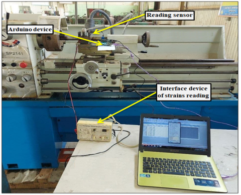
The present work's experimental rig was put up in the workshop of Almusaib Technical Institute. Horizontal turning machine with high-speed steel cutting tool. The strain gauge is attached to the cutting edge by an interface device, which measures cutting tool strains and then converts the readings to a computer programme. The thermocouple is linked to the other side of the cutting tool, and an amplifier is used to amplify the responses. The thermocouple is then connected to an Arduino, which then translates the temperature readings from the cutting tool to a computer programme, as shown in Figure 1.
Figure 1. Experimental set up of the current study
In the first state, the lubricant process of the cutting tool is performed on the top tool face by lubricant liquid whose properties are illustrated in Table 1 [18]. In the second state, the lubricant process of the cutting tool is done in three directions by the same of lubricant liquid and air compressed with liquid to enhance the performance of the cutting tool and to reduce strain and temperature as shown in Figure 2.
Table 1. Details of the lubricant liquid
|
Stuff |
Office |
Contact: (%Vol./Vol. of fixed oil) |
|
Fixed oil |
Base oil |
80% |
|
Washing soap |
Emulsifier |
10% |
|
Carbolic acid |
Germicide |
5% |
|
Sculpture |
Extreme |
5% |
Figure 2. Lubricant process in three directions on cutting tool
According to the previous studies, can express about the theoretical model of the current study as shown below:
Cutting power $=F_c \cdot V_c$ (1)
$e_{t h}=\gamma \cdot(\Delta T) \cdot L$ (2)
$e_{t h}-e_R=\Delta$ (3)
$\gamma(\Delta T) L-\frac{F \cdot L}{A \cdot F}=\Delta$ (4)
$\frac{\Delta}{L}=e=\operatorname{strain}$ (5)
$e=\gamma \cdot \Delta T-\frac{F}{A \cdot E}$ (6)
where:
$\Delta T=T_{\text {tool }}-T_{\text {lubricant oil befor cutting }}$
$A_{\text {square cross section of tool }}=l^2=(10 \mathrm{~mm})^2$
$ \quad \gamma= cofficent\,\, of\,\, heat\,\, translate=11.8 * 10^{-6} \frac{m}{w} C^0$
The simulation process is done by Auto Desk Inventor program for different cutting speeds. Explicit dynamic methods are used to estimate the stress and strain in the cutting tool. In this research, sold cutting tool material (HSS) with dimensions of (60*8*8) mm cross section, (15º) Rag angle (α), (10º) Tolerance angle, (75) Tool angle (β) and (8) mm tool edge width is used for the analysis process. The mechanical properties of these materials are listed in the Table 2.
Table 2. Mechanical Properties of (HSS) materials
|
No. |
Properties |
Values |
|
1 |
Ultimate tensile strength |
540 MPa |
|
2 |
Poisson’s ratio |
0.28 |
|
3 |
Young’s modulus |
233 GPa |
|
4 |
Mass density |
7.6 kg/m3 |
|
5 |
Yield strength |
250 MPa |
|
6 |
Specific heat |
0.42 [J/(kg·K)] |
|
7 |
Thermal Expansion Coff. |
12.6×10 – 6 [K−1] |
|
8 |
Thermal conductivity |
20.2 [W/(m·K)] |
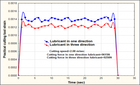
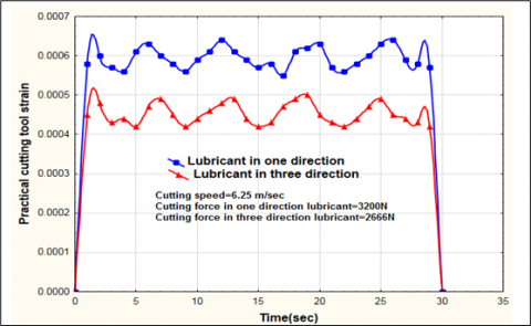
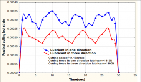
The interface equipment records strains readings of cutting tool in two cases of lubricant process and in different cutting speed as shown in Figures 3, 4, 5, and 6. Also, the Arduino device records temperature readings of cutting tool with changing of cutting speed and inconstant cutting depth (0.4mm) as shown in Figures 7, 8, 9, and 10.
Figure 3. The practical strain readings of the cutting tool at a cutting speed 2.08m/sec
Figure 4. The practical strain readings of the cutting tool at a cutting speed 6.25 m/sec
Figure 5. The practical strain readings of the cutting tool at a cutting speed 10.4m/sec
Table 1 shows volumetric ratios of lubricant liquid. The oil ratio is high percentage as well as the soap ratio, which helps to prevent chip slipping on the rack angle surface. Figure 1 shows the three directions of lubricant liquid flow with compression air to reduce cutting temperature and strain, which are produced on the tool edge and in the interface region between tool and work piece, and then keep the tool and work piece from deformation by reducing temperature and strain on the surfaces of tool and work piece.
Figure 6. The practical strain readings of the cutting tool at a cutting speed 14.16 m/sec
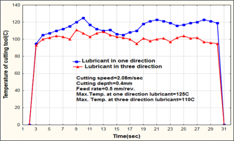
Figure 7. The practical temperatures of a cutting tool in speed 2.08m/sec
Figure 8. The practical temperatures of a cutting tool in speed 6.25m/sec
The practical Figures 3, 4, 5, 6 show the relationship between cutting time, which is limited to 30 seconds, and practical strains by interface device, which depends on the changing of whatston bridge resistance as in Figure 1, which gives digital strain reais dings by computer program. The response is by a strain gauge (120 Hz) fitted on the cutting tool edge. The property of strain gauge helps to get the maximum strain value during 30 seconds.
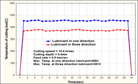
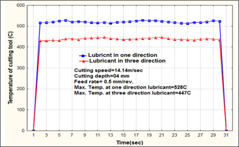
The practical Figures 7, 8, 9, 10 illustrate the relationship between cutting tool temperature in a close region from the cutting edge by a thermocouple fitted in this region of the cutting tool and cutting time is limited by 30 seconds. The readings are recorded for two lubricant flows in one direction and in three directions at different cutting speeds. The maximum cutting temperature is specified for the previous two lubricant states. At cutting speed (2.08 m/sec) in Figure 7, cutting temperatures in two lubricant states are more closely related, especially at 13 seconds from cutting time, as shown in Figure 3, for the same speed at strain reading. This refers to true practical results for strains and temperatures readings. While in Figures 8, 9, and 10, the difference between the temperatures of the two lubricant states is stable and constant approximately. The maximum temperature difference between two lubricant states for different speeds (2.08, 6.25, 10.4, 14.16) is (15, 70, 78, 81 Co). The results refer to an increase in cutting speed due to the improvement of the lubricant process, and as in strain readings, the cutting speed (10.4 m/sec) gives good results for cutting tool temperature and strains.
Figure 9. The practical temperatures of a cutting tool in speed 10.4m/sec
Figure 10. The practical temperatures of a cutting tool in speed 14.14m/sec
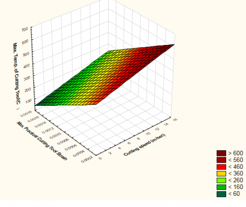
Figures 11 and 12 show the difference between lubricant in one direction and three directions with maximum values of strains and temperatures of cutting tool.
Moving to the numerical results, when turning tool collides in in work piece to start cutting process, the constraining of cutting tool is occur between tool fixing region and work piece, because of longitudinal vibration in turning tool and that is led to effect on metal tool as displacement, strains, stresses. They are translating to tool root; therefore, the tool temperature increases because of compression force in opposite direction of its feed rate. The tool deformation has isotropic and proportional with temperature variation. The strain function with temperature variation, coefficient of thermal expansion is constant value [19, 20].
Figure 11. The relationship between Max. Temperatures, Strains and Cutting Speed in one direction of lubricant
Figure 12. The relationship between Max. Temperatures, Strains and Cutting Speed in three directions of lubricant
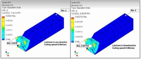
Figure 13. The simulation of one and three direction lubricant in cutting process at 2.08m/sec
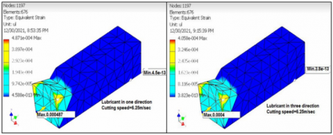
Figure 14. The simulation of one and three direction lubricant in cutting process at 6.25m/sec
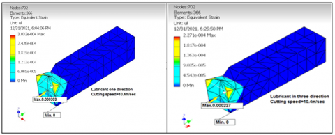
Figure 15. The simulation of one and three direction lubricant in cutting process at 10.4m/sec
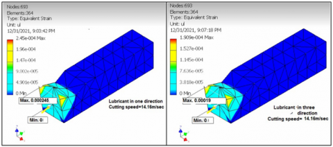
Figure 16. The simulation of one and three direction lubricant in cutting process at 14.16m/sec
Table 3. The theoretical, practical and simulation results of turning tool strains
|
Simulation strains of 3D lubricant |
Simulation strains of 1D lubricant |
Practical strains of 3D lubricant |
Practical strains of 1D lubricant |
Theoretical Strains of 3D lubricant |
Theoretical Strains of 1D lubricant |
Cutting speed m/sec |
|
0.00173 |
0.0018 |
0.00138 |
0.00144 |
0.0003 |
0.0004 |
2.08 |
|
0.0004 |
0.000487 |
0.00048 |
0.0006 |
0.00268 |
0.00343 |
6.25 |
|
0.000227 |
0.000303 |
0.00029 |
0.000387 |
0.00392 |
0.00483 |
10.4 |
|
0.00019 |
0.000245 |
0.00025 |
0.00032 |
0.00511 |
0.006 |
14.16 |
As mentioned earlier, the simulation process is done by Auto Desk Inventor program for different cutting speeds as illustrated in Figures 13, 14, 15, 16 and the results of theoretical, practical and simulation strains are inserted in Table 3.
The Auto Desk inventor programme generated simulation Figures 13, 14, 15, and 16 that were subjected to the same loads values on the shear surface of the cutting tool in two cases of one-direction lubricant and three-direction lubricant with changing cutting speed (2.08, 6.25, 10.4, and 14.16 m/sec) and strain difference between two cases of lubricant (0.000068, 0.000087, 0.000076, 0.000055). The results show the high difference in strain is in the second speed (6.25m/sec), but the strain value of the third speed is close to the strain value of the second speed. Therefore, this refers to the convergence of simulation results with experimental and theoretical that this speed is the best for cutting tool (HSS) during the cutting process. Hence, the correction factor between experimental and theoretical results is (0.425), while that between experimental and simulation results is (0.428) as shown in Table 3. This refers to convergence of simulation and experimental results because the correction factor is very small, while unconference of theoretical and experimental results occurs because thermal stress is added to the value of the cutting force effect, and this can be taken in experimental values as an added ratio.
The present investigation yields the following conclusions:
[1] Mir, M.J., Wani, M.F. (2018). The influence of cutting fluid conditions and machining parameters on cutting performance and wear mechanism of coated carbide tools. Jurnal Tribologi, 18: 58-80.
[2] Hussein, M.A., Abbas, A.A., Abdul-Nabe, R.A. (2018). Enhancement the mechanical properties of the deep drawing products through intelligence design and finite element analysis. Jour Adv Res. Dyn. Control Syst, 10(13): 2156-2169.
[3] Bouzid, L., Berkani, S., Yallese, M., Girardin, F., Mabrouki, T. (2018). Estimation and optimization of flank wear and tool lifespan in finish turning of AISI 304 stainless steel using desirability function approach. International Journal of Industrial Engineering Computations, 9(3): 349-368. https://doi.org/10.5267/j.ijiec.2017.8.002
[4] Berkani, S., Yallese, M., Boulanouar, L., Mabrouki, T. (2015). Statistical analysis of AISI304 austenitic stainless steel machining using Ti (C, N)/Al2O3/TiN CVD coated carbide tool. International Journal of Industrial Engineering Computations, 6(4): 539-552. https://doi.org/10.5267/j.ijiec.2015.4.004
[5] Benedicto, E., Rubio, E.M., Aubouy, L., Sáenz-Nuño, M.A. (2021). Formulation of sustainable water-based cutting fluids with polyol esters for machining titanium alloys. Metals, 11(5): 773. https://doi.org/10.3390/met11050773
[6] Wickramasinghe, K.C., Sasahara, H., Abd Rahim, E., Perera, G.I.P. (2020). Green Metalworking Fluids for sustainable machining applications: A review. Journal of Cleaner Production, 257: 120552. https://doi.org/10.1016/j.jclepro.2020.120552
[7] Chan, C.H., Tang, S.W., Mohd, N.K., Lim, W.H., Yeong, S.K., Idris, Z. (2018). Tribological behavior of biolubricant base stocks and additives. Renewable and Sustainable Energy Reviews, 93: 145-157. https://doi.org/10.1016/j.rser.2018.05.024
[8] Ogedengbe, T.S., Okediji, A.P., Yussouf, A.A., Aderoba, O.A., Abiola, O.A., Alabi, I.O., Alonge, O.I. (2019). The effects of heat generation on cutting tool and machined workpiece. In Journal of Physics: Conference Series, 1378(2): 022012. https://doi.org/10.1088/1742-6596/1378/2/022012
[9] Ogedengbe, T.S., Awe, P., Joseph, O.I. (2019). Comparative analysis of machining stainless steel using soluble and vegetable oils as cutting fluids. International Journal of Engineering Materials and Manufacture 4(1):33-40. https://doi.org/10.26776/ijemm.04.01.2019.05
[10] Songmene, V., Zaghbani, I., Kientzy, G. (2018). Machining and machinability of tool steels: Effects of lubrication and machining conditions on tool wear and tool life data. Procedia CIRP, 77: 505-508. https://doi.org/10.1016/j.procir.2018.08.252
[11] Ozimina, D., Kowalczyk, J., Madej, M., Nowakowski, Ł., Kulczycki, A. (2017). The impact of the type of cutting fluid on the turning process. Tribologia, 273(3): 119-126. https://doi.org/10.5604/01.3001.0010.6149
[12] Chen, D., Wu, S., He, Y., Li, S., Luo, Y., Wang, X. (2021). Comparison analysis between simulation and experiment of cutting force and cutting stress as well as chip morphology during the macro and nano cutting of single crystal copper. The International Journal of Advanced Manufacturing Technology. https://doi.org/10.21203/rs.3.rs-849526/v1
[13] Zhou, L., Wang, Z., Wen, H. (2019). On the accuracy of the Johnson-Cook constitutive model for metals. Chinese Journal of High Pressure Physics, 33(4): 3-16.
[14] Ravi, S., Gurusamy, P., Mohanavel, V. (2020). A review and assessment of effect of cutting fluids. Materials Today: Proceedings, Journal. www.elsevier.com/locate/matpr.
[15] Agrawal, S.M., Patil, N.G. (2018). Experimental study of non-edible vegetable oil as a cutting fluid in machining of M2 Steel using MQL. Procedia Manufacturing, 20: 207-212. https://doi.org/10.1016/j.promfg.2018.02.030
[16] Araújo, R.P., Rolim, T.L., Oliveira, C.A., Moura, A.E., Silva, J.C.A. (2019). Analysis of the surface roughness and cutting tool wear using a vapor compression assisted cooling system to cool the cutting fluid in turning operation. Journal of Manufacturing Processes, 44: 38-46. https://doi.org/10.1016/j.jmapro.2019.05.040
[17] Kumar, P., Ravi, S. (2021). Investigation on effects of vegetable-based cutting fluids in turning operation of “EN 24 Steel”. Materials Today: Proceedings, 39: 95-99. https://doi.org/10.1016/j.matpr.2020.06.315
[18] Sahu, S., Mondal, D.P., Goel, M.D., Ansari, M.Z. (2018). Finite element analysis of AA1100 elasto-plastic behaviour using Johnson-Cook model. Materials Today: Proceedings, 5(2): 5349-5353. https://doi.org/10.1016/j.matpr.2017.12.120
[19] García-Martínez, E., Miguel, V., Martínez-Martínez, A., Manjabacas, M.C., Coello, J. (2019). Sustainable lubrication methods for the machining of titanium alloys: An overview. Materials, 12(23): 3852. https://doi.org/10.3390/ma12233852
[20] Lin, Y., Liu, Y.T., Chang, Y.W. (2019). An investigation of the temperature-drift effect on strain measurement of concrete beams. Applied Sciences, 9(8): 1662. https://doi.org/10.3390/app9081662