Ahmed M. Saheb* | Bashar Sakeen Farhan
© 2022 IIETA. This article is published by IIETA and is licensed under the CC BY 4.0 license (http://creativecommons.org/licenses/by/4.0/).
OPEN ACCESS
This paper presents a modern charging system to improve the reliability of locating the closest and available free charging slot to charge low-power smart-devices. Also, the presented system is based on the cloud and the used network is based on the internet of things technology. The basic idea of the charging system is to provide a public charging place for all individuals who wish to charge their smart devices when it is close to running out. First and foremost, the charging system was designed and implemented to have multiple power sources in the event that one of the system's power sources failed. Secondly, the charging system provides a special smart mobile application that has also been designed and implemented, which allows the user to know the locations of the charging systems on a map and choose the nearest available system near the user. After selecting the nearest charging system, the user will be able to know whether or not there is an available charging port and the number of associated devices in each system. The study successfully built this system in practical life.
IoT, smart-charging system, cell phone, multi-source
Currently, the world is witnessing an increasing growth in the use of smart devices [1] and the rapid development of the Internet of Things [2] and its entry into various aspects of daily life [3].
From the above, it is clear that users should remain connected continuously on the Internet, which requires the provision of continuous and multiple sources of charging, especially in critical periods and places where there are no sources of electrical power for the purpose of conducting the charging for mobile devices. Technical solutions to life problems increase the efficiency of the system, increase accessibility and reduce dependence on the human element.
The main idea of the study by Zhang et al. [4] was to design a remote-control plug based on Wi-Fi to control appliances by smartphone. The main components of this design were the power supply, which accepts only 220 volts and the output power is 5 volts, the relay which provides a connection between home appliances and input power, and the ESP8266 module, which is used to connect the smartphone with the plug when the smartphone is inside the Wi-Fi range. In this design, the main power is only 220 Volte and there are no supplementary power supplies (Solar cells and batteries). There is no feedback from the plug to the Smartphone device to confirm that the home appliance has been turned on/off. The design doesn't deal with failure tolerance of the system, and the researchers don't mention anything about the applied algorithm. They also don't mention anything about the smartphone application that will control the plug.
Sindhuja and Balamurugan [5] designed a system to control and monitor the loads of home appliances. The home devices that consume power are monitored by an ARM controller, which is stored in a database over the cloud. Based on this data, the user will control the home devices by turn on/off these devices-based on the user's need to minimise the consumed power. In this work, there is no operation confirmation from the home devices to the user.
Brito-Rojas et al. [6] proposed a prototype design and development of a low-priced solar cell smartphone charger. The idea of this project is to reduce the growing amount of energy consumed by smartphones, which will lead to a reduction in global warming. In this work, the proposed prototype circuit design needs more development due to many design problems. Also, the proposed system provides single user use (not for public users).
Patel et al. [7] used a Wi-Fi module called ESP8266 to implement the TCP and MQTT protocols in this work. MQTT and TCP protocols are implemented in the ESP8266 Wi-Fi module. With the help of this Wi-Fi module, the user can monitor and control their home appliances. With the help of this Wi-Fi device, they can control and monitor and control their home instruments, such as lights, TVs, or any other electronic device.
In order to resolve the shortcomings of the systems referred to above and inspired in ref. [1-4] and some related works [8], the current study presents a new charging system based on IoT. First, our charging system uses a mechanism that uses a mechanism to search for the charging system's location in real time and find an empty slot that could be used for charging. Second, if the current charging system is full (no available slots for charging), the user will check another charging system location by using a map. Third, guarantee the charging system is on most of the time by providing different sources of power to the system. A network of charging systems is introduced such that each charging system is a node in a network. The slot status of each node will be updated instantaneously. This increases the probability of discovering an unused charging slot at a particular location. In contrast to other charging systems, our system provides greater availability. Our system is evaluated through designation and implementation. The implemented system provides better performance than the other systems. The proposed charging system allows users to charge their devices in public places, find the location of these charging systems, find an empty slot for charging, and the charging system uses different sources of energy to increase the availability of the system in different conditions. The system will help users to save their businesses by allowing them to be available online. It will also reduce the probability of turning off the device. We have successfully implemented the charging system.
In this paper, a smart system was designed and implemented for the purpose of providing a public charger and being multi-energy (220 volts, batteries, and solar panels). It supports various electronic devices and a smart application was designed and implemented for the purpose of determining the nearest location of charging systems on the map, whether the mobile device has an Internet connection or not, with the possibility of recognising the status of these charging systems (whether the system works or not, is there an empty charging port or not). As a final result, the system provides charging for mobile devices from multiple sources in different circumstances and in general areas, and to know the location of these systems was provided, an electronic application was provided to find out the nearest available location for these systems with the possibility of knowing the status of the system.
2.1 System outline
The charging system uses a proximity sensor to monitor the charging system. A proximity sensor reads the free charging slot in each charging system. The use of proximity sensors enables large-scale system implementation at low cost [9]. The charging system helps to reduce wasted time in the search for a free charging slot. Upon running the charging system application, the user can find the free and available charging slots in each charging system. Details of every charging system will be shown to the user via a map over a web application. When a new phone is attached to the charging slot, the charging system will change the status of the charging slot from ‘available’ to ‘reserved’ based on the proximity sensor reading. Therefore, the overall charging system status is dynamically updated in real time. The charging system will help to identify the charging time for each charging slot in real time. The charging system adopts a mechanism to guarantee the availability of charging power by having many sources of electricity. Changing from one source to another will happen dynamically and automatically based on the priority of the power source.
2.2 Architecture of charging system
Figure 1 demonstrates a smart charging system based IoT. The system elements:
i. Cloud-Server
It is a web-based system which stores the resource data gathered by the sensing unit located in each charging slot. The system helps the end user locate the charging system and find information about free charging slots for every charging system by accessing the cloud server directly, without the need to access the charging system node directly.
ii. Hardware System
The hardware system is located in every charging system, stores the status of each charging slot and chooses the best source of power, as shown in Figure 2. The hardware system contains the following:
1. Power Control Unit
It is an Arduino microcontroller board [10], which is available in every charging system node to control the choosing of the source of power from different sources (main power 220v, solar cells, and battery) based on the priority number given to each source of power. To communicate the Arduino module together with the cloud server, the internet connection is used to pass data from the current charging system to the database of the cloud server.
2. Sensing unit
It is the proximity sensor, which is used to check the availability of charging slots in the charging system node by sending the sensing data from charging system slot to cloud server database via an Internet connection at every change.
iii. Client Software System
In this software system, the end user can find the full details about each charging system, as shown in Figure 2. The client software system includes the following:
It is a smartphone mobile application designed and implemented to operate on the Android OS (operating system). End users must download and install it on their mobile devices and use it to find charging system node locations, the total number of charging slots, the free charging slots, and a map of charging system nodes. The users can access the system through Wifi/3G/4G connections.
It is a smartphone mobile application that can be downloaded from the Google Play Store [11]. The idea of this application is to provide a simple messaging between client and cloud server by using the MQTT (Message Queuing Telemetry Transport) protocol [12], which is designed to fit constrained resource devices with low resources, therefore it is used widely in IoT projects. Based on the previously mentioned MQTT protocol, the smart charging system will send an MQTT message to inform the cloud server that a new smartphone device is added to the charging port or disconnected from the charging port. Here, the smart charging system is responsible for sending the data to the cloud server. That's if we look from the smart charging system side.
But if we look from the smartphone device side, it will communicate with the cloud server when the mobile application is initiated, the cloud server will send all the information it received from the smart charging system to the application and this information will appear in the interface of the mobile application which shows whether the system is It available or not, as well as showing whether there are empty ports that can be used, as it shows the occupied charging ports.
Figure 1. Architecture of smart charging system based IoT
Figure 2. Charging system details (Client-to-Server)
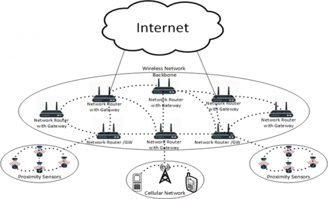
Figure 3. Infrastructure/backbone design
2.3 Architecture of charging system network
The infrastructure/backbone design [11] is used for the charging system network, as shown in Figure 3, where the wireless connection is represented by dotted lines and the wired link is represented by solid lines. In the charging network, the router is used as an infrastructure to connect the end users where the gateway feature enables the routers to connect to the internet. Wireless technologies could be used in infrastructure/backbone to connect the charging system nodes between each other.
The following sections are organised to describe the charging system operation in both parts of the operations and the hardware system.
3.1 Operations of software system
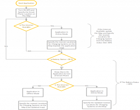
If the end user's mobile device’s battery is diminished to a threshold value, then the end user must find a charging slot, and he must run the client software system. After successful running, a request is sent to search for a charging system. Then, the cloud server will send back a response containing the detailed information, including the charging system nodes' locations on the map and the detailed information about free charging slots in each charging node. The end user will choose the charging system node based on the nearest location according to the current location and availability of the free charging slot. If there is no free charging slot in the current charging system current charging system slots are full, the user will check another charging system, as shown in Figure 4.
Figure 4. Describe the operation of software system
Figure 5. Simplified block diagram for the smart charging system
3.2 Operations of hardware system
In Figure 5, a simplified block diagram for the smart charging system is presented. It consists of a power supply module with multi-energy sources like a 220v main power supply, solar cell, 12v battery backup, voltage regulators, microcontroller, and a WIFI module. The sensors section supports the MCU (microcontroller unit) with the appropriate information about the voltage sources' existence and the battery levels. The system communicates with the server through the WIFI Module to upgrade the system's status. The MCU section uses the Arduino Uno as a compromise between cost and simplicity. Finally, the output port supports the USB connector of the 5V/1A specification.
3.2.1 Charging Current Calculation (current sensor)
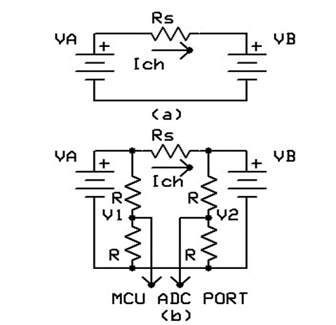
According to electrical circuit theory, the charging current Ich flows in the circuit shown in Figure 6a could be determined by using Eq. (1) [13].
$I c h=(V A-V B) / R s$ (1)
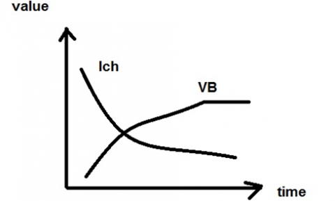
where, VA the is charging battery, Ich is the charging current and VB is the battery under charging. When VB values increased, the Ich values decreased as shown in Figure 7.
To make the MCU read instantaneous Ich value, the circuit in Figure 6a will be modified to the circuit in Figure 6b. This modification will protect the MCU input port from damage because the MCU deals with 5 volts only and VA is greater than 5 volts. To derive Ich equation of Figure 6b as shown:
Figure 6. Charging current sensor circuit
Figure 7. Charging current vs. time relationship
$V 1=V A R /(R+R)$ (2)
$V 1=V A / 2$ (3)
$V A=2 V 1$ (4)
And the same procedure V2 equation could be found as:
$V 2=V B / 2$ (5)
$V B=2 V 2$ (6)
Substitute Eqns. (4) and (5) into Eq. (1) yields:
$I c h=2(V 1-V 2) / R s$ (7)
3.2.2 System design diagram
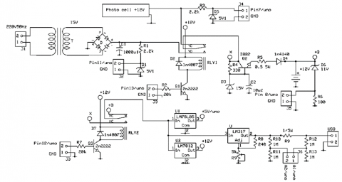
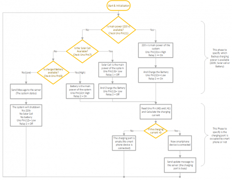
Figure 8 and Figure 9 represent the block diagram and schematic diagram of the power supply module. Three types of energy are shown; 220v main power, solar cell, and battery backup. Sensors are used to sense which energy type is found and the system gives high priority to the 220v main power, then to solar, then to the backup battery. Finally, if the battery is the only source that exists and it is continuously giving power to the system, a sensor watches the battery level. If it reaches 11v, the system shuts down to protect the battery from discharging anymore. Then the system shuts down waiting for any source to charge the battery and wake up the system again. The mechanism of the smart charging system can be simply explained using a flowchart as shown in Figure 10. Figure 10 simply illustrates the system's working cycle. The Arduino will check pin (11) port if it is high or low. If high, 220v exists and the backup battery is in charge, the Arduino checks pin (7) or pin (8) for other types of power to feed the system and send information to update the system status.
Figure 8. Power supply module block diagram
Figure 9. Power supply module schematic diagram
Figure 10. Smart system flow chart
A client software system is designed and implemented specially to operate on an Android platform-based smartphone [12], but it can also operate on any web browser-based device. The client software system was implemented from the scratch to allow developers to build convincing mobile apps that take maximum benefit of all that a smartphone can give. In this step, we’re using the Android Software Development Kit SDK (Frameworks, Version 24.3.4), which is a suite of programming tools used to create applications-based Android framework which can use the command prompt to implement Android Apps. The cloud-based web server is deployed using MOT (Master of Things). MOT is an IDE (integrated development environment) that uses JavaScript for development. The built-in MOT database is used as a database for wide-scale data collection and handling.
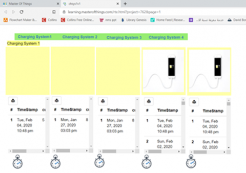
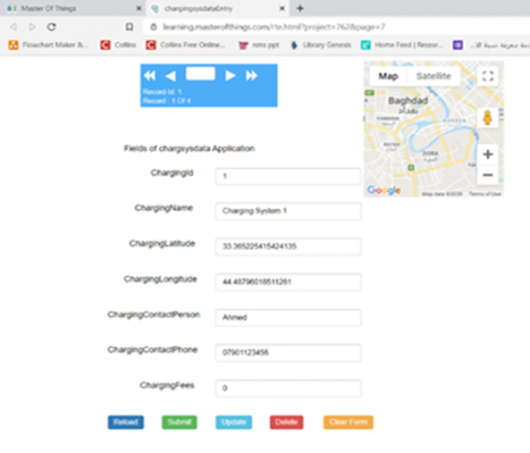
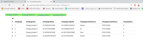
Figure 11a illustrates the location and distribution of each charging system on the map with specific details. Figure 11b describes the real-time status of each charging slot (free or busy) in a visualised manner and provides the ability to move from one charging system to another. Figure 11c shows the admin panel which is used to add a new charging system node on the map with some details. This panel includes a mini-map for specifying the charging system's longitude and latitude. Figure 11d illustrates the charging system name, longitude, latitude and etc.
(a)
(b)
(c)
(d)
Figure 11. (a) Charging system location; (b) Real-time status of each charging slot; (c) Admin panel to add a new charging system node; (d) Charging system name
Figure 12 illustrates the charging system node implementation (hardware and software) for one port in the Lab environment. When a phone was connected to the charging port as the user was asking for a service, a current flowed and Arduino had determined the charging current using Eq. (7) by measuring only V1 and V2 voltages.
Figure 12. Charging port in action
In this research paper, an integrated charging system has been designed and successfully implemented in a real environment. This system is multi-source and available in public places to provide charging for mobile devices. The charging system will be connected to the Internet with the possibility of providing Wi-Fi coverage to users who do not have an Internet service. It is possible to know the status of the system (On/Off and available charging ports) and charging system location through a mobile application designed for this purpose. In this design, the low costs were taken into account, relying mainly on basic electronic components with the capability of system production in the local market. The use of this charging system will help and serve many people in various emergency situations and even in developing business environments that require social communication with customers.
[1] Alam, T. (2018). A reliable framework for communication in internet of smart devices using IEEE 802.15. 4. ARPN Journal of Engineering and Applied Sciences.
[2] Madakam, S., Lake, V., Lake, V., Lake, V. (2015). Internet of Things (IoT): A literature review. Journal of Computer and Communications, 3(5): 164-173. https://doi.org/10.4236/jcc.2015.35021
[3] Dineshreddy, V., Gangadharan, G.R. (2016). Towards an “Internet of Things” framework for financial services sector. In 2016 3rd International Conference on Recent Advances in Information Technology (RAIT), Dhanbad, India, pp. 177-181. https://doi.org/10.1109/RAIT.2016.7507897
[4] Zhang, Y.P., Liu, T., Yang, Z.X., Mou, Y., Wei, Y.H., Chen, D. (2015). Design of remote control plug. In 2015 IEEE International Conference on Applied Superconductivity and Electromagnetic Devices (ASEMD), pp. 29-30. https://doi.org/10.1109/ASEMD.2015.7453451
[5] Sindhuja, P., Balamurugan, M.S. (2015). Smart power monitoring and control system through internet of things using cloud data storage. Indian Journal of Science and Technology, 8(19). https://doi.org/10.17485/ijst/2015/v8i19/76698
[6] Brito-Rojas, J.A., Aguilar-Calderón, J.A., Garcia-Sanchez, O., Tripp-Barba, C., Zaldívar-Colado, A., Misra, S. (2014). A low-cost solar cell charger prototype for smartphone's battery charging. In 2014 IEEE 6th International Conference on Adaptive Science & Technology (ICAST), Ota, Nigeria, pp. 1-5. https://doi.org/10.1109/ICASTECH.2014.7068137
[7] Patel, K.K., Patoliya, J., Patel, H. (2015). Low cost home automation with ESP8266 and lightweight protocol MQTT. Transactions on Engineering and Sciences, 3(6): 14-19. https://doi.org/10.1109/R10-HTC.2016.7906845
[8] Pham, T.N., Tsai, M.F., Nguyen, D.B., Dow, C.R., Deng, D.J. (2015). A cloud-based smart-parking system based on Internet-of-Things technologies. IEEE Access, 3: 1581-1591. https://doi.org/10.1109/ACCESS.2015.2477299
[9] Herz, S.M., Yepez, R.G., Westerman, W.C., Hotelling, S.P. (2013). U.S. Patent No. 8,600,430. Washington, DC: U.S. Patent and Trademark Office.
[10] Sarhan, Q.I. (2020). Systematic survey on smart home safety and security systems using the Arduino platform. IEEE Access, 8: 128362-128384. https://doi.org/10.1109/ACCESS.2020.3008610
[11] Delap, L. (2006). ‘Thus does man prove his fitness to be the master of things’: Shipwrecks, chivalry and masculinities in nineteenth-and twentieth-century Britain. Cultural and Social History, 3(1): 45-74. https://doi.org/10.1191/1478003805cs044oa
[12] Naik, N. (2017). Choice of effective messaging protocols for IoT systems: MQTT, CoAP, AMQP and HTTP. In 2017 IEEE international systems engineering symposium (ISSE), Vienna, Austria, pp. 1-7. https://doi.org/10.1109/SysEng.2017.8088251
[13] Theraja, B.L. (2008). A Textbook of Electrical Technology. S. Chand Publishing.