Djamel Khezzar* | Djamel Khedrouche | Tayeb A. Denidni
© 2021 IIETA. This article is published by IIETA and is licensed under the CC BY 4.0 license (http://creativecommons.org/licenses/by/4.0/).
OPEN ACCESS
This paper provides a numerical investigation in designing wideband circularly polarized 60 GHz antenna using Low-Temperature Co-fired Ceramic technology (LTCC). The LTCC provides high-density multilayer integration, low dielectric loss, and low costs. The use of LTCC technology is advantageous for easy and flexible 3D integration and freer vias distribution in the substrate. The designed antenna focuses on obtaining a better trade-off in terms of size, gain, circular polarization (CP), and large bandwidth. The circular polarization was chosen in order to minimize the transmission errors caused by polarization inconsistency between the transmitter and the receiver. The antenna geometry is developed taking into consideration the design rules of the LTCC with a layer thickness of 100 µm after firing and a metal layer thickness of 9 µm. A bandwidth of more than 33% centered at 60 GHz was obtained for this designed multilayer antenna. The results are obtained by using the High-Frequency Structure Simulator (HFSS). The proposed integrated antenna can be used in future 5G wireless communication systems and other 60 GHz spectrum applications.
LTCC, millimeter waves, microstrip antenna, 5G
The extension of wireless communication systems to the millimeter-wave spectrum has attracted great interest. Indeed, the unlicensed 60 GHz frequency band has become a potential candidate for the next generation of communication to meet the demand for high traffic capacity. The small size, wideband, and high-performance requirements of the microwave spectrum are the main advantages of the millimeter-wave spectrum. The focus on millimeter-wave technology is due to its ability to transmit a large amount of data with low transmission power in short-range indoor and outdoor wireless communications [1-5].
The antenna is an indispensable element of any wireless communication system. At the millimeter waves, it exhibits several design challenges such as limited gain, complex structure, higher-order mode losses, etc. The microstrip antenna is the better choice for millimeter-wave devices due to its compactness, conformity, integrability, and ease of fabrication [6]. This type of antenna has a wide range of applications in wireless communication systems, especially in mobile communication devices [7]. However, a fundamental drawback of conventional patch antennas is a narrow impedance bandwidth which is generally less than 5% of the operating center frequency [8]. To improve the impedance bandwidth of microstrip antenna, a large body of research has been conducted, leading to several improvement techniques, which include the use of cavities, metamaterials, and stacked structures [9-11]. However, this additional manufacturing process increases the complexity of the circuit and the manufacturing cost. Besides, at this frequency range, the antenna manufacturing exhibits significant tolerances. Thus, the antenna design difficulties move away from the structural challenges to the manufacturing process to reduce the manufacturing tolerances. LTCC technology provides high-density multilayer integration, low dielectric loss, and low costs. The use of LTCC technology is advantageous for easy and flexible 3D integration and freer vias distribution in the substrate, which makes the LTCC method suitable for the design of compact and light antennas for high operating frequencies [12, 13].
This paper aims to provide a broadband antenna in order to meet the demand for high-speed data in the 5G cellular mobile systems. This proposed antenna is circularly polarized which permits to receive linearly polarized (LP) waves in an arbitrary direction. Therefore, it minimizes significantly the transmission errors caused by the polarization inconsistency [14, 15]. To minimize the manufacturing cost, the proposed multilayer antenna design is simplified and enhanced by avoiding the use of vias, cavities, and metamaterial surfaces, etc. In order to achieve these goals, a parametrical study is applied as a guiding technique for the numerical simulation to optimize the antenna structure, looking for better accuracy in terms of resonance frequency, wider bandwidth, an adequate gain, and good impedance matching compared to the relevant reported antennas.
In the rest of this paper, section two presents the antenna geometry and the design approach based on the parametrical study. The obtained results of the proposed antenna using HFSS (High-Frequency Structure Simulator) are presented and discussed in section 3, while section 4 concludes the paper.
Figure 1(a) shows the top and cross-section view of the designed structure. The antenna is designed to achieve wide bandwidth and circular polarization using an irregular hexagon shape. The proposed antenna is based on LTCC multilayer technology for 3D vertical integration of different antenna elements. The radiating element is placed on the top layer and fed using strip line feeding structure on the sixth layer. These two elements are separated by the top ground in the seventh layer and connected by a vertical probe in the substrate and the created slot in the top ground. This feeding structure is used to increase the ability to use a thicker substrate in order to achieve a wideband. This proposed structure is simplified to minimize the fabrication cost, by reducing the number of vias and the total module size without the use of cavities. The antenna geometry has been developed respecting the LTCC technology design rules. The layer thickness is 100 µm for each tape after firing. The metal layer type is gold with a thickness of 9 µm. the design criteria of the LTCC antenna are shown in Table 1.
Table 1. LTCC design criteria
|
Dielectric permittivity |
er = 5.9 |
Number of layers for top substrate |
NL = 4 |
|
Loss Tangent |
tand = 0.002 |
Conductor type |
Gold |
|
Layer thickness |
100 µm |
Number of layers for down substrate |
NL = 7 |
|
The metal layer thickness |
9 µm |
Taking the previous parameters as constants, we assume that the radiating element is a rectangular patch in order to determine the desired operating frequency. The length of the conventional patch determines the operating frequency, and the width of the antenna controls its impedance. For better accuracy in terms of resonance frequency and according to the cavity model for microstrip antenna, the length of the antenna should be calculated by taking into consideration the fringe coupling effect. The width and the effective length of the supposed rectangular radiating element are calculated using a MATLAB algorithm. In order to get more accuracy in terms of the desired center frequency, the calculated length of the antenna needs to be more adjusted using a parametrical study. Similarly, the width is calculated and adjusted to have a better impedance matching response. By increasing or minimizing the length and width of the antenna, the parametric study aims to achieve a better compromise between these two parameters at the desired center frequency.
After defining the rectangle patch width and length, the corners of the radiator element are truncated to have an irregular hexagon shape. All hexagon dimensions have been adjusted in addition to the feed width and length, the probe diameter and position for a better compromise between many desired but incompatible features of the antenna such as resonant frequency, bandwidth, impedance, axial ratio, etc. Hence, another parametric study includes all dimensional parameters of the antenna is applied. The parametrical study permits more than three-dimensional parameters to be varied while the other parameters are fixed in a constant value. Figure 1(b) illustrates a flow chart of the methodology based on the parametric study. This design process is repeated until the reach of a configuration that satisfies the design needs in terms of antenna performances and the desired optimizations. The optimum dimensions of the antenna that gives circularly polarized and broad impedance bandwidth are given in Table 2. The radiating element is placed on an LTCC substrate with a thickness of h0= 0.4 mm from the top ground to the radiating element, h1 = 0.1 mm from the integrated stripline to the top ground and h2 = 0.7 mm from the down ground to the stripline. the total antenna height is h0 + h1 + h2.
Table 2. Antenna parameters
|
Parameter |
Length |
|
|
a |
0.52 mm |
0.104ʎ0 |
|
b |
0.49 mm |
0.098ʎ0 |
|
c |
0.438 mm |
0.0876ʎ0 |
|
Feed length |
1.743 mm |
0.3486ʎ0 |
|
Probe radius |
0.05 mm |
0.01ʎ0 |
|
Probe height |
0.50 mm |
0.1ʎ0 |
|
Slot radius |
0.24 mm |
0.048ʎ0 |
(a)
(b)
Figure 1. (a) antenna geometry, (b) flow chart of the design methodology
The simulated results of this LTCC based antenna are obtained using High-Frequency Structure Simulator (HFSS), which enables fast and accurate analysis of high-frequency devices such as filters, couplers, antennas, planar and multi-layer structures. Figure 2 shows the surface current distribution for the designed antenna. According to this figure, the surface current is minimal in the radiating slots and maximal in the non-radiating slots (inverse to the voltage in the radiating slots). This helps to define the radiating corners and the associated effective length that directly affect the resonance frequency.
Figure 2. Surface current distribution
Figure 3 shows the plot of return loss as a function of frequency. The related bandwidth is defined as the frequency range where the return loss is less than 10 dB. The solver shows an impedance bandwidth of 33% that covers the unlicensed frequency spectrum around 60 GHz. Two resonance frequencies are observed according to the return loss graph. A good impedance matching is obtained because of the good choice of probe position to connect the strip line to the radiating element. The same probe allows the use of a thicker substrate for getting larger bandwidth. However, the substrate thickness should be chosen carefully to not allow surface wave propagation.
Figure 3. Return loss
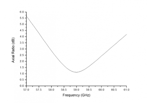
To make the antenna circularly polarized, two orthogonal modes must be excited. This is assured by the use of the irregular hexagonal form of the radiating element. Figure 4 shows the obtained plot for the Axial ratio characteristic of the designed antenna. The antenna is circularly polarized in the frequency interval where the axial ratio is less than 3 dB. This design result has a center frequency of 59 GHz with a bandwidth of 2.383 GHz ranging from 57.94 GHz up to 60.33 GHz.
Figure 4. Axial ratio
Figure 5 illustrates the corresponding VSWR of the designed antenna, which points how well antenna terminal input impedance is matched to the characteristic impedance of the transmission line. In the ideal case, the VSWR equals 1.0 which means no power is reflected from the antenna. However, when the VSWR is less than 2, it remains a good impedance matching between antenna and feed. According to the obtained curves of the VSWR, a good impedance matching to the bandwidth frequency range as it is noted less than 2. The closer VSWR to 1, the better the antenna is matched to the transmission line, and the more power is delivered to the antenna. According to the return loss and VSWR curves, the designed antenna has a wide bandwidth ranging from 52.7 GHz to 72.8 GHz.
Figure 5. VSWR
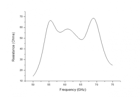
The real part of the antenna impedance is illustrated in Figure 6. At the frequency range of interest, the antenna input resistance is around 50 ohms. For the ideal case, the antenna input impedance equals 50 ohms which means the power that arrives at the antenna is radiated away. Otherwise, the received power is absorbed by the antenna. The obtained curve of the antenna resistance (real part of the antenna input impedance) shows a good impedance matching at the considered frequency spectrum.
Figure 6. Antenna resistance
The imaginary part of the input impedance in Figure 7 represents the power that is stored in the near field of the radiator. This power is not considered as a radiated power. An antenna with zero reactance and real input impedance (zero imaginary part) is considered to be resonant at the corresponding frequency. The obtained results of the antenna reactance (imaginary part of the antenna input impedance) show a good impedance matching at the considered frequency spectrum.
Figure 7. Antenna reactance
Figure 8 shows the 2D radiation pattern in the E-plan and H-plane of the designed antenna. The energy radiated by an antenna is represented by its Radiation pattern. this diagrammatical representation defines the variation of the power radiated by an antenna as a function of the direction away from the antenna and shows the distribution of radiated energy into space.
In order to verify the stability of the radiation pattern of this designed antenna across the considered frequency bandwidth, the 3D radiation pattern is illustrated in Figure 9. According to this figure, this antenna has another important factor of performance in terms of stability of the produced radiation pattern for given frequencies 55 GHz, 60 GHz, and 65 GHz. The antenna has maximal radiation in the Z-axis and independent of frequency across the considered bandwidth. The performance in terms of the gain of this antenna is about 4,9 dBi. This obtained gain is acceptable for a single radiator element at this range of the spectrum, where the antenna element becomes too small as its size needs to be scaled with wavelength. These obtained results of the proposed antenna are compared to recent similar works in Table 3. A 60 GHz antenna was designed based on LTCC technology. It shows a bandwidth of 16.16 % and a gain of 4.9 dBi [5]. The obtained S11 parameter is -27dB. In [11], three antennas are proposed using LTCC technology. These antennas have a peak bandwidth and a peak gain of 22.7 % and 4.8 dBi respectively. The deeper S11 parameter obtained is -36 dB. Accordingly, our proposed 60 GHz radiator has a higher gain, wider bandwidth, and a deeper S11. Moreover, the proposed design is simplified and enhanced without using complicated structures such as cavities and metamaterial surfaces.
Figure 8. 2D radiation pattern
Figure 9. 3D radiation pattern
Table 3. Comparison of the proposed antennas to the relevant reported antennas
|
Antenna |
Technology |
Center Frequency (GHz) |
S11 (dB) |
BW (GHz) |
BW |
GAIN (dBi) at 60 GHz |
Year |
|
Proposed antenna |
LTCC |
60 |
-43 |
19.8 |
33% |
4.9 |
- |
|
[5] |
LTCC |
60 |
-27 |
10 |
16.6% |
4.9 |
2016 |
|
[11] |
LTCC AMC1 |
60 |
-29 |
13.3 |
22.1% |
4.8 |
2019 |
|
LTCC AMC2 |
60 |
-36 |
13.7 |
22.7% |
4.4 |
||
|
LTCC AMC3 |
60 |
-23 |
8.6 |
13.7% |
4.8 |
This work presents a design of a 60-GHz antenna for bandwidth and gain enhancement using LTCC technology. The proposed antenna has been designed and simulated with HFSS software. The design shows a good impedance matching with a peak gain of about 4.9 dBi, a good radiation pattern response, and a bandwidth of more than 33% centered at 60 GHz. Hence, these obtained results stand for better trade-off in terms of size, gain, CP, and bandwidth. The proposed antenna has the advantage of wide bandwidth, adequate gain, planar form, and the ability of integration using LTCC multilayer technology. These performances make this antenna a good candidate for future wireless communications components and other millimeter-wave applications.
This work was supported by the Algerian Ministry of Higher Education and Scientific Research via funding through the PRFU project.
No. A25N01UN280120180001.
[1] Singh, S., Chawla, M. (2017). A review on millimeter wave communication and effects on 5G systems. IARJSET, 4(7): 28-33. https://doi.org/10.17148/iarjset.2017.4705
[2] Seker, C., Guneser, M.T., Ozturk, T. (2018). A review of millimeter wave communication for 5G. 2018 2nd International Symposium on Multidisciplinary Studies and Innovative Technologies (ISMSIT), Ankara, Turkey. https://doi.org/10.1109/ismsit.2018.8567053
[3] Rappaport, T.S., Xing, Y., MacCartney, G.R., Molisch, A.F., Mellios, E., Zhang, J. (2017). Overview of millimeter wave communications for fifth-generation (5G) wireless networks-with a focus on propagation models. IEEE Transactions on Antennas and Propagation, 65(12): 6213-6230. https://doi.org/10.1109/tap.2017.2734243
[4] Barakat, A., Pokharel, R., Elsadek, H. (2017). Innovative Techniques for 60-GHz On-Chip Antennas on CMOS Substrate. In Microwave Systems and Applications. InTech. https://doi.org/10.5772/66238
[5] Ali, I., Chang, R.Y., Liu, J.Y.C. (2016). Multilayer CPW-fed patch antenna on new AMC ground plane for 60 GHz millimeter-wave communications. 2016 IEEE 83rd Vehicular Technology Conference (VTC Spring), Nanjing, China. https://doi.org/10.1109/vtcspring.2016.7504357
[6] Agarwal, S., Singh, D. (2018). CPW-fed concurrent, dual band planar antenna for millimeter wave applications. International Journal of Microwave and Wireless Technologies, 10(9): 1088-1095. https://doi.org/10.1017/s1759078718001009
[7] Bondarik, A., Sjoberg, D. (2015). Investigation of reconfigurability for a stacked microstrip patch antenna pattern targeting 5G applications. 2015 IEEE-APS Topical Conference on Antennas and Propagation in Wireless Communications (APWC), Turin, Italy. https://doi.org/10.1109/apwc.2015.7300200
[8] Xu, K.D., Xu, H., Liu, Y., Li, J., Liu, Q.H. (2018). Microstrip patch antennas with multiple parasitic patches and shorting vias for bandwidth enhancement. IEEE Access, 6: 11624-11633. https://doi.org/10.1109/access.2018.2794962
[9] Lee, H.J., Li, E.S., Jin, H., Li, C.Y., Chin, K.S. (2019). 60 GHz wideband LTCC microstrip patch antenna array with parasitic surrounding stacked patches. IET Microwaves, Antennas & Propagation, 13(1): 35-41. https://doi.org/10.1049/iet-map.2018.5226
[10] Dzagbletey, P.A., Jung, Y.B. (2018). Stacked microstrip linear array for millimeter-wave 5G baseband communication. IEEE Antennas and Wireless Propagation Letters, 17(5): 780-783. https://doi.org/10.1109/lawp.2018.2816258
[11] Lee, H.J., Li, E. S., Li, C.Y., Lin, Y.Y., Lu, R., Chin, K.S. (2019). Bandwidth and gain enhancement of LTCC 60-GHz patch antenna by using AMC structure. Journal of Electromagnetic Waves and Applications, 33(11): 1463-1476. https://doi.org/10.1080/09205071.2019.1614483
[12] Zaid, J., Farahani, M., Denidni, T.A. (2016). A compact circularly-polarized GPS antenna using LTCC technology. Microwave and Optical Technology Letters, 58(12): 2926-2929. https://doi.org/10.1002/mop.30183
[13] Kim, J.S., Moon, S.M., Oh, H.M., Kim, C.Y. (2016). A fully integrated LTCC Wilkinson power divider/combiner using a parasitic compensated 100 OHM RF resistor for 60 GHz wireless applications. Microwave and Optical Technology Letters, 58(3): 720-722. https://doi.org/10.1002/mop.29659
[14] Guo, L., Tang, M.C., Li, M. (2018). A low-profile dual-layer patch antenna with a circular polarizer consisting of dual semicircular resonators. Sensors, 18(6): 1773. https://doi.org/10.3390/s18061773
[15] Sun, L., Ou, G., Lu, Y., Tan, S. (2013). Axial ratio bandwidth of a circularly polarized microstrip antenna. In Advancement in Microstrip Antennas with Recent Applications. InTech. https://doi.org/10.5772/54664