OPEN ACCESS
Numerical investigation of an electrically conducting micropolar fluid having steady incompressible flow with heat and mass transfer towards a stagnation point through a porous medium on a vertical plate is obtained in the present study. The effects of heat generation i.e. source /absorption i.e. sink and first order chemical reaction are also discussed. The governing non-dimensional form of the nonlinear coupled ordinary differential equations are formulated using similarity technique and then the solution of these transformed equations are obtained numerically using Runge-Kutta fourth order method associated with shooting technique. The validation of the present result is confirmed with the earlier published work which is solved by Finite Difference Method. The effect of pertinent physical parameters govern the flow phenomena are presented through graphs, and numerical computation of rate of shear stress, rate of heat and mass transfer are presented using tables.
micropolar fluid, porous medium, assisting and opposing flow, stagnation point, numerical solution
Micropolar fluid dynamics has been playing a significant role in processing industries. Therefore many scientists have been working in this area. The theory of microplar fluids took birth from Eringen in 1966. Most of the fluids have been used in the processing industries are non-Newtonian. These fluids with microstructure have immense applications in biology, industry, technology. Due to large scale applications of the hydromagnetic stagnation point flows past through heated or cooled bodies in the field of engineering and natural processes have attracted many researchers to examine the characteristic of fluid flow. So studies on behaviour of these fluids are carried by many scientists in recent years. Bhargava et al. (2000) have studied the characteristics of heat transfer of micropolar boundary layer in a moving wall near a stagnant point. The microrotation of fluid elements, the effects of the couple stresses and spin inertia are very much important in micropolar fluids which are studied by Eringen (1964). Stagnation point flow of classical two dimensional fluid on a flat plate was studied by Hiemenz (1911). Wang (1978) was investigated impinging stagnation flow of two fluids of different densities. Mahapatra and Gupta (2001) have studied two dimensional MHD steady stagnation point flow towards a stretching surface.
Recently, Pal and Biswas (2016) studied oscillatory flow of micropolar fluid in the presence of heat sink and thermal radiation. Mishra et al. (2015) investigated flow of MHD free convective micropolar fluid with heat source. Srinivas Raju et al. (2016) examined heat absorption effects MHD free convection flow past over a vertical plate both by analytically (Laplace transform method) and numerically (Finite Element Method).
Mathematical modelling and numerical analysis of heat and mass transfer and their effects in different geometries are studied by Alam et al. (2016) (stretching/shrinking wedge), Mishra et al. (2013), Tripathy et al. (2016). Effect of variable surface temperature on steady MHD stagnation point flow over a stretching sheet was studied by Ishak et al. (2009). Recently, Lok et al. (2010) examined and analysed the flow of a micropolar fluid over a shrinking sheet where shrinking and ambient fluid velocity were assumed to vary linearly with the stagnation point. The laminar mixed convection in two-dimensional stagnation flows around surfaces was studied by Ramachandran et al. (1988).
Hassanien et al. (1990) and Devi et al. (1991) have extended the work of Ramachandran on micropolar fluid to unsteady case where they found dual solution exists for a certain range of the buoyancy parameter. Stagnation point over a vertical surface in the presence of thermal radiation and viscous dissipation was examined by Olanrewaju et al. (2011) and Manjoolatha et al. (2013). MHD flow of a visco-elastic fluid through a porous medium has been investigated by Baag et al. (2015). Dash et al. (2016) studied stagnation-point flow past a stretching/shrinking sheet problem numerically.
However, to the best of our knowledge, the main aim of the present investigation is to find numerical solutions of heat and mass transfer of magnetohydrodynamic (MHD) micropolar fluid flow towards a stagnation point on a vertical plate through porous medium. Additional heat source is also taken into account in the energy equation. In our present problem we discussed for both the case of strong (n=0) and weak (n=1/2) concentrations those have not considered by El-dabe et al. (2015). The similarity transformation is applied to transfer the governing partial differential equations into nonlinear ordinary equations and have been solved numerically by using Runge-Kutta method of order four followed by shooting technique. Comparison of the present result with earlier published result in a particular case employing finite difference method. The effects of various parameters of the problem characterize the flow phenomena have been analyzed through figures and tables.
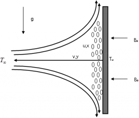
In this study a two dimensional flow system is considered. Along x-axis a heated vertical stretching sheet embedded in a porous medium is placed (Figure 1) through which a steady flow near the stagnant point of MHD incompressible micropolar fluid has been experimented. The half plane (y>0) is occupied by the fluid. Further, it is assumed that the boundary layer velocity U, the sheet temperature Tw and concentration Cw are proportional to the distance from stagnant point. Mathematically U=px, Tw=T∞+qx and Cw=C∞+rx where p,q,r are positive constants. Both Tw and Cw are greater than T∞ and C∞ respectively. T∞ and C∞ are uniform temperature and concentration respectively of the fluid. The magnetic field strength B0 is uniform, applied normal to stretching plate in the positive direction of y-axis. In this flow study the magnetic Reynolds number is too small which avoid induced magnetic field.
The governing equations for this flow are
$\frac { \partial u } { \partial x } + \frac { \partial v } { \partial y } = 0$ (1)
$u \frac { \partial u } { \partial x } + v \frac { \partial u } { \partial y } = U \frac { d U } { d x } + \left( \frac { \mu + \kappa } { \rho } \right) \frac { \partial ^ { 2 } u } { \partial y ^ { 2 } } + \frac { \kappa } { \rho } \frac { \partial \omega } { \partial y } + \left( \frac { \sigma B _ { 0 } ^ { 2 } } { \rho } + \frac { \mu } { \rho K p ^ { * } } \right) ( U - u )$ $\pm g \beta \left( T - T _ { \infty } \right) \pm g \beta ^ { * } \left( C - C _ { \infty } \right)$ (2)
$u \frac { \partial \omega } { \partial x } + v \frac { \partial \omega } { \partial y } = \frac { \gamma } { \rho j } \frac { \partial ^ { 2 } \omega } { \partial y ^ { 2 } } - \frac { k } { \rho j } \left( 2 \omega + \frac { \partial u } { \partial y } \right)$ (3)
$u \frac { \partial T } { \partial x } + v \frac { \partial T } { \partial y } = \alpha \frac { \partial ^ { 2 } T } { \partial y ^ { 2 } } + \frac { v } { c _ { p } } \left( \frac { \partial u } { \partial y } \right) ^ { 2 } - \frac { 1 } { \rho c _ { p } } \left( \frac { \partial q _ { r } } { \partial y } \right)$$+ \frac { D _ { m } k _ { T } } { c _ { s } c _ { p } } \left( \frac { \partial ^ { 2 } C } { \partial y ^ { 2 } } \right) + \frac { Q } { \rho c _ { p } } \left( T - T _ { \infty } \right)$ (4)
$u \frac { \partial C } { \partial x } + v \frac { \partial C } { \partial y } = D _ { m } \frac { \partial ^ { 2 } C } { \partial y ^ { 2 } } + \frac { D _ { m } k _ { T } } { T _ { m } } \left( \frac { \partial ^ { 2 } T } { \partial y ^ { 2 } } \right) - K c ^ { \cdot } \left( C - C _ { \infty } \right)$ (5)
Figure 1. Schematic diagram
With boundary conditions as given below
$\left.\begin{array} { l l } { u = 0 , v = 0 , \omega = - n \frac { \partial u } { \partial y } , T = T _ { w } , C = C _ { w } , } & { \text { at } y = 0 } \\ { u \rightarrow U ( x ) , \omega \rightarrow 0 , T \rightarrow T _ { \infty } , C \rightarrow C _ { \infty } } & { \text { as } y \rightarrow \infty } \end{array} \right\}$ (6)
Where u, v are x and y components of velocity, the cp, Dm, Tm, KT, cs and the acceleration due to gravity, g, fluid temperature, T, fluid concentration, C, kinematic viscosity of the fluid, v, thermal and solutal expansion coefficient, β, β*, radiative heat flux, and chemical reaction coefficient, Kr respectively. Whereas ρ, μ, k, j, ω, γ, α are fluid density, dynamic viscosity, vortex viscosity, microinertia density, microrotation velocity, spin gradient viscosity and thermal diffusivity.
The following stream function and similarity transformations are used
$\left.\begin{array} { l } { \eta = \sqrt { \frac { a } { v } } y , \psi = \sqrt { a v } x f ( \eta ) = , \omega = a x \sqrt { \frac { a } { v } } h ( \eta ) } \\ { j = \frac { v } { a } , \theta ( \eta ) = \frac { \left( T - T _ { \infty } \right) } { \left( T _ { w } - T _ { \infty } \right) } , \phi ( \eta ) = \frac { \left( C - C _ { \infty } \right) } { \left( C _ { w } - C _ { \infty } \right) } } \end{array} \right\}$ (7)
to transform the systems of equations from (1) to (5) with their corresponding boundary conditions as ordinary.
Here the independent variable η is the similarity variable used for transformation and f(η), g(η), θ(η), Ø(η) are respectively the dimensionless stream function, microrotation, temperature, concentration whereas Ψ is the stream function which is defined in its usual way.
$u = U f ^ { \prime } ( \eta ) , v = - \sqrt { a v } f ( \eta )$ (8)
Prime denotes the differentiation with respect to η.
We get the following ordinary differential equations by the above transformations
$( 1 + K ) f ^ { \prime \prime \prime } + f f ^ { \prime \prime } + 1 - f ^ { \prime 2 } + K g + \left( M + \frac { 1 } { K p } \right) \left( 1 - f ^ { \prime } \right) \pm \lambda _ { 1 } \theta \pm \lambda _ { 2 } \phi = 0$ (9)
$\left( 1 + \frac { K } { 2 } \right) g ^ { \prime \prime } + f g ^ { \prime } - f ^ { \prime } g - K \left( 2 g - f ^ { \prime \prime } \right) = 0$ (10)
$\left( 1 + \frac { 4 } { 3 } R d \right) \theta ^ { \prime \prime } + \operatorname { Pr } f \theta ^ { \prime } - \operatorname { Pr } f ^ { \prime } \theta + \operatorname { Pr } E c f ^ { \prime \prime 2 } + \operatorname { Pr } D u \phi ^ { \prime \prime } + \operatorname { Pr } S \theta = 0$ (11)
$\phi ^ { \prime \prime } + S c f \phi ^ { \prime } - S c f ^ { \prime } \phi + S c S r \theta ^ { \prime \prime } - S c K c \phi = 0$ (12)
Here the parameter $M = \frac { \sigma B ^ { 2 } } { a \rho }$ is the magnetic parameter, $\lambda _ { 1 } = \pm \frac { G r } { R _ { e x } ^ { 2 } } , \lambda _ { 2 } = \pm \frac { G m } { R _ { e x } ^ { 2 } }$ are the thermal buoyancy parameter and solutal buoyancy parameter respectively. When λ1<0, λ2<0, the bouncy forces act as in the direction of the mainstream and fluid is accelerated in the manner of a favourable pressure gradient and λ1<0, λ2<0, buoyancy forces oppose the motion, retarding the fluid in the boundary layer, acting as an adverse pressure gradient. $G r = \frac { g \beta \left( T _ { w } - T _ { \infty } \right) } { v ^ { 2 } } , G m = \frac { g \beta ^ { * } \left( C _ { w } - C _ { \infty } \right) } { v ^ { 2 } }$ and $R _ { ex} = \frac { L \overline { x } } { v }$ are called the local thermal Grashof number, the local soutal Groshof number, the local Reynolds number respectively:
$E c = \frac { U ^ { 2 } } { c _ { p } \left( T _ { w } - T _ { \infty } \right) } , \operatorname { Pr } = \frac { v \rho c _ { p } } { \kappa } , R d = \frac { 4 \sigma T _ { \infty } ^ { 3 } } { \kappa \kappa ^ { * } } , S c = \frac { v } { D } , K c = \frac { K c ^ { * } } { a }$ are the Eckert number, Prandtl number, radiation parameter, Schmidt number, Chemical reaction parameter respectively. $D u = \frac { D _ { m } k _ { T } c x } { v c _ { s } c _ { p } b x } = \frac { D _ { m } k _ { T } \left( C _ { w } - C _ { \infty } \right) } { v c _ { s } c _ { p } \left( T _ { w } - T _ { \infty } \right) }$, Dufour number and $S r = \frac { D _ { m } k _ { T } b x } { v T _ { m } c x } = \frac { D _ { m } k _ { T } \left( T _ { w } - T _ { \infty } \right) } { v T _ { m } \left( C _ { w } - C _ { \infty } \right) }$, the Soret number.
The corresponding boundary conditions are
$\left.\begin{array} { l } { f ( 0 ) = 0 , f ^ { \prime } ( 0 ) = 0 , g ( 0 ) = - n f ^ { \prime \prime } ( 0 ) , \theta ( 0 ) = 1 , \phi ( 0 ) = 1 } \\ { f ^ { \prime } ( \infty ) \rightarrow 1 , g ( \infty ) \rightarrow 0 , \theta ( \infty ) \rightarrow 0 , \phi ( \infty ) \rightarrow 0 } \end{array} \right\}$ (13)
The major physical quantities of interest are the skin friction coefficient Cf, Nusselt number Nu, and Sherwood number Sh, which are defined as
$C _ { f } = \frac { \tau _ { w } } { \rho U ^ { 2 } / 2 } , \quad N u = \frac { x q _ { w } } { k \left( T _ { w } - T _ { \infty } \right) } , \quad S h = \frac { x q _ { m } } { D _ { m } \left( C _ { w } - C _ { \infty } \right) }$ (14)
where surface shear stress, surface heat and mass flux are defined as
$\tau _ { w } = \left[ ( \mu + \kappa ) \frac { \partial \iota } { \partial y } + \kappa \omega \right] _ { y = 0 } q _ { w } = - k \left( \frac { \partial T } { \partial y } \right) _ { y = 0 } \quad q _ { m } = - D _ { m } \left( \frac { \partial C } { \partial y } \right) _ { y = 0 }$ (15)
Using the non-dimensional variables (8), we get from Eqs. (14) and (15) as
$\frac { 1 } { 2 } C _ { f } \operatorname { Re } _ { x } ^ { 1 / 2 } = \left( 1 + \frac { K } { 2 } \right) f ^ { \prime } ( 0 ) , \frac { N u } { \operatorname { Re } _ { x } ^ { 1 / 2 } } = - \theta ^ { \prime } ( 0 ) , \frac { S h } { \operatorname { Re } _ { x } ^ { 1 / 2 } } = - \phi ^ { \prime } ( 0 )$ (16)
In the present investigation an electrically conducting micropolar fluid flow over a vertical stretching sheet embedded in a porous medium is discussed. Physical significance of the pertinent physical parameters characterizes the flow phenomena such as magnetic parameter (M), porous matrix (Kp), thermal buoyancy parameter (L1), solutal buoyancy parameter (L2), Prandtl number (Pr), heat source/sink parameter (S), material parameter (K), radiation parameter (Rd), Eckert number (Ec), Dufour number (Du), Soret number (Sr), Schmidt number (Sc) and chemical reaction parameter (Kc) have been presented and discussed through graphs. The numerical computations for skin friction coefficient, rate of heat transfer (Nusselt number) and rate of mass transfer (Sherwood number) are obtained and presented in a table. The validation of the present result with that of the earlier published result of Ramchandran et al. (1988), Lok et al. (2010) and Ishak et al. (2009) have also made in a particular case and these are presented in Table-1. In the absence of magnetic parameter (M=0) and Pr=0.7 the result is in good agreement with the results of Ramchandran et al. (1988), Lok et al. (2010) and Ishak et al. (2009). Also in the absence of M=0 and Pr=1, present result is in good agreement with the published result of Ishak et al. (2009). Furher, it is observed that increase in magnetic parameter skin friction increases which resulted in decrease n velocity boundary layer. Whereas, increase in Prandtl number skin friction decreases.
The novelty of the present investigation is to bring out the effects of additional parameters introduced in the flow problem such as porous parameter (Kp), and solutal buoyancy parameter (L2) in the momentum equation, heat generation / absorption parameter (s) in the eqution of energy. Another speciality of the investigation is the role of buoyant forces. Here λ1>0, λ2>0, represent the assisting flow(bold lines) and λ1>0, λ2>0, opposing flow (dotted lines). To validate the present result we have compared our result with the result of Ishak et al. (2012) and El-dabe et al. (2015) in a particular case.
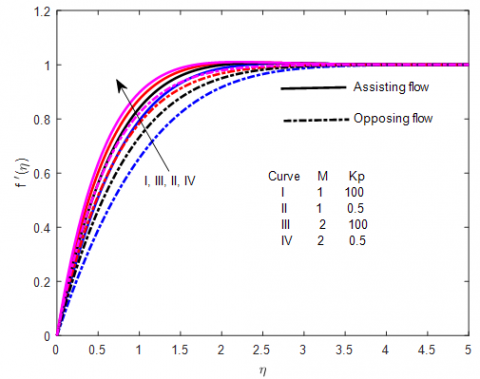
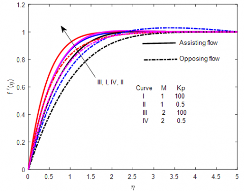
Figure 2 and 3 exhibit the effect of magnetic parameter in the absence / presence of porous matrix on the velocity and microrotation profiles respectively for both the case of assisting and opposing flows and the absence of surface condition parameter (n=0). For non-Newtonian case (K=1), our result well agrees with Ishak et al. (2009) in the absence of magnetic parameter. It also seen that increase in magnetic parameter enhance the velocity profiles. As a result velocity boundary layer thickness decreases for both the presence / absence of porous matrix. Maximum rise in velocity remarked in case of assisting case (Figure 2). Further, microrotation profile (Figure 3) has reverse trend as that of velocity. It is interesting to note that angular velocity remains negative in the boundary layer where profiles intersect at η=1.75 (approximately) for both assisting and opposing cases. This indicates that, the same layer represents transition state after which the opposite effect is remarked i.e. angular velocity increases to with an increase in magnetic parameter.
Figure 4 and 5 illustrate the effect of magnetic parameter in the absence / presence of porous matrix on the velocity and microrotation profiles respectively for both the case of assisting and opposing flows and the absence of surface condition parameter (n=0.5). It is observed that increase in magnetic parameter the velocity profile decreases in case of non-Newtonian parameter (K=1). This is due to the fact that, Lorentz force is a resistive force which retards the velocity profile significantly (Figure 4). Similar characteristic is remarked in microrotation profile for increasing values of magnetic parameter but angular velocity becomes maximum in case of assisting flow as that of opposing flow (Figure 5).
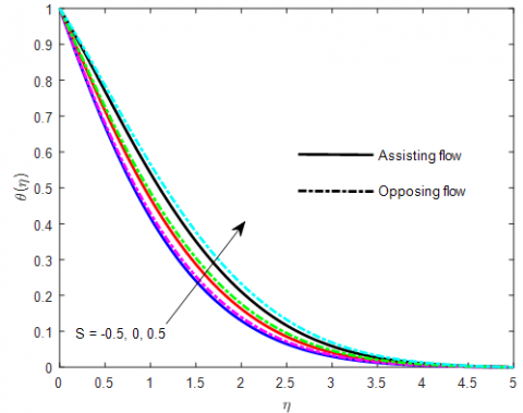
Figure 6 presents the effect of heat source / sink on the temperature profiles. This clearly indicates that increase in source strength, the temperature of the micropolar fluid increases for both the buoyancy assisting and opposing flow whereas the sink strength retards the temperature significantly.
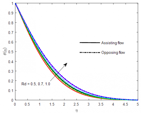
Figure 7 and 8 exhibits the effects of radiation parameter and Dufour number on the temperature profiles. It is seen that the temperature of the micropolar fluid increases with increase in both radiation and Dufour number. According to the definition of radiation parameter, an increase in Rd implies decrease of absorption coefficient which leads to more radiative heat flux, so the rate of energy transport to the fluid and the values of temperature distribution are raised. The Dufour number denotes the contribution of the concentration gradients to the thermal energy flux in the flow. It can be seen that an increase in the Dufour number causes a rise in temperature. The trend is opposite for opposing flow.
The effect of chemical reaction parameter, Kc on concentration profiles for both assisting and opposing cases is shown in Figure 9. It is observed that the concentration boundary layer thickness decreases as an increase in chemical reaction parameter resulted in decrease in concentration of micropolar fluid. This is due to the presence of heavier species in the polar fluid.
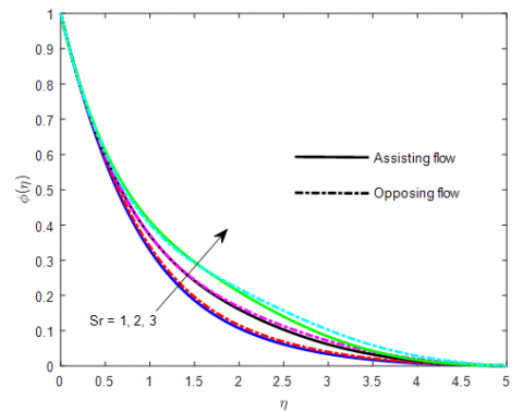
Figure 10 presents the effect of Soret number on the concentration profile for fixed values of the pertinent parameter characterizes the flow phenomena. It is clear to remark that, increase in Soret number concentration of the fluid increases. The Soret number denotes the contribution of the temperature gradients to the mass flux in the flow, resulted in rise in concentration of the micropolar fluid.
Figure 2. Effect of M and Kp on velocity profiles for n=0, K=1, λ1=λ2=0.5
Figure 3. Effect of M and Kp on microrotation profiles for n=0, K=1, λ1=λ2=0.5
Figure 4. Effect of M and Kp on velocity profiles for n=0.5, K=1, λ1=λ2=0.5
Figure5. Effect of M and Kp on microrotation velocity profilesfor n=0.5, K=1, λ1=λ2=0.5
Figure 6. Effect of S on temperature profiles for n=0.5, K=1, λ1=λ2=0.5, Pr=0.71, Ec=0.1, Rd=0.5, Du=0.1
Figure 7. Effect of Rd on temperature profiles for n=0.5, K=1, λ1=λ2=0.5, Pr=0.71, Ec=0.1, S=0.5, Du=0.1
Figure 8. Effect of Du on temperature profiles for n=0.5, K=1, λ1=λ2=0.5, Pr=0.71, Ec=0.1, S=0.5, Du=0.1
Figure 9. Effect of Kc on concentration profiles for Sc=0.22, Sr=0.1, n=0.5, K=1, λ1=λ2=0.5, Pr=0.71, Ec=0.1, S=0.5, Du=0.1
Figure 10. Effect of Sr on concentration profiles Sc=0.22, Kc=0.5 n=0.5, K=1, λ1=λ2=0.5, Pr=0.71, Ec=0.1, S=0.5, Du=0.1
Table 1. Comparison table for skin friction coefficient fʹʹ(0)
|
M |
Pr |
Ramchandran et al. (14) |
Lok et al.(13) |
Ishak et al.(15) |
present |
|
0 |
0.7 |
1.7063 |
1.70636 |
1.7063 |
1.70918 |
|
1 |
0.7 |
1.9921355 |
|||
|
0 |
1 |
1.6755 |
1.678802 |
||
|
1 |
1 |
1.967458 |
The numerical computations of rate of shear stress i.e. skin friction coefficient, rate of heat and mass transfer are obtained and presented in Table-1 for different values of the pertinent parameters and fixed values of other parameters characterizes in the flow phenomena. It is observed that the increasing value of magnetic parameter, thermal and solutal buoyancy decreases the skin friction in magnitude whereas an increase in material parameter, N increases the skin friction coefficient. Also all the parameters except heat source and destructive chemical reaction decreases the rate of heat transfer whereas reverse effect is remarked for rate of mass transfer. Further, sink reduces the rate of heat transfer and constructive chemical reaction is desirable to increase the rate of mass transfer.
Table 2. Skin friction coefficient fʹʹ(0), Nusselt number -θʹ(0), Sherwood number -Øʹ(0)
|
M |
Pr |
Kp |
K |
n |
S |
Kc |
fʹʹ(0) |
-θʹ(0) |
-Øʹ(0) |
|
0 |
0.7 |
100 |
0 |
0.5 |
0 |
0 |
2.2825 |
0.6165 |
0.51237 |
|
1 |
2.4844 |
0.6173 |
0.51399 |
||||||
|
1 |
2.4637 |
0.6985 |
0.51023 |
||||||
|
3 |
2.4153 |
1.0073 |
0.49954 |
||||||
|
1 |
0.5 |
2.8515 |
0.6216 |
0.51742 |
|||||
|
1 |
2.1650 |
0.6088 |
0.49940 |
||||||
|
2 |
1.8511 |
0.5968 |
0.486313 |
||||||
|
1 |
2.5 |
4.0249 |
0.6589 |
0.59351 |
|||||
|
0.5 |
-0.5 |
2.2030 |
0.7373 |
0.49846 |
|||||
|
0.5 |
2.2283 |
0.4635 |
0.50678 |
||||||
|
-1 |
2.2529 |
0.4741 |
0.29717 |
||||||
|
1 |
2.2114 |
0.4554 |
0.66963 |
From the above discussion the following conclusions are made:
Angular velocity remains negative in the boundary layer for both assisting and opposing cases.
Velocity becomes maximum for assisting flow.
Buoyancy assisting and opposing flow are favourable to enhance the temperature of the micropolar fluid.
The rate of energy transport to the fluid and the values of temperature distribution are raised as an increase in radiation parameter.
An increase in Soret number, concentration of the fluid increases.
Sink reduces the rate of heat transfer and constructive chemical reaction is desirable to increase the rate of mass transfer.
|
C: Fluid concentration |
D Coefficient of the mass diffusivity |
|
Pr Prandtl number |
g Acceleration due to gravity |
|
M Magnetic parameter |
S heat source/sink parameter |
|
cp Specific molecular diffusivity |
Kc chemical reaction parameteR |
|
Sc Schmidt number |
Sr Soret number |
|
T Fluid temperature |
Du Dufour number |
|
T∞ Fluid temperature at infinity |
C Species concentration |
|
B0 Magnetic flux density |
ω Angular velocity vector |
|
Sh Sherwood number |
u,v Velocity components |
|
kf Thermal conductivity |
along x- and y-direction |
|
Nu Nusselt number |
j Micro-inertia density |
|
γ Chemical reaction parameter |
Cw Stretching sheet concentration |
|
Ec Eckert number |
K Material parameter |
|
Tw Stretching sheet temperature |
|
|
Greek symbols |
|
|
σ Electrical conductivity |
|
|
λ1 Thermal buoyancy |
|
|
ρ Density of the fluid |
|
|
v Kinematic viscosity |
|
|
δ Solutal buoyancy parameter |
|
|
η Similarity variable |
|
|
θ(η) Dimensionless temperature |
|
|
β heat source/sink parameter |
|
|
Ø(η) concentration profile |
|
|
μ Dynamic viscosity |
|
|
K Vortex viscosity |
|
|
λ2 mass buoyancy |
|
|
α Thermal diffusivity |
|
Alam S., Islam T., Uddin M. J. (2016). Mathematical modelling for heat transfer of a micropolar fluid along a permeable stretching/shrinking wedge with heat generation/absorption. Mathematical Modelling of Engineering Problems, Vol. 3, No. 1, pp. 1-9. http://doi.org/10.18280/mmep.030101
Baag S., Acharya M. R., Dash G. C., Mishra S. R. (2015). MHD flow of a visco-elastic fluid through a porous medium between infinite parallel plates with time dependent suction. Journal of Hydrodynamics, Vol. 27, No. 5, pp. 840-847. http://doi.org/10.1016/S1001-6058(15)60536-4
Bhargava R., Takhar H. S. (2000). Numerical study of heat transfer characteristics of the Micropolar boundary layer near a stagnation point on a moving wall. Int. J. Eng. Sci., Vol. 38, pp. 383-394. http://doi.org/10.1016/s0020-7225(99)00051-8
Dash G. C.,Tripathy R. S., Rashidi M. M., Mishra S. R. (2016). Numerical approach boundary layer stagnation-point flow past a stretching/shrinking sheet. Journal of Molecular Liquids, Vol. 221, pp. 860-866. http://doi.org/10.1016/j.molliq.2016.06.072
Devi C. D. S., Takhar H. S., Nath G. (1991). Unsteady mixed convection flow in stagnation region adjacent to a vertical surface. Heat and Mass Transfer, Vol. 26, pp. 71-79. http://doi.org/10.1007/BF01590239
El-Dabe1 N. T., Ghaly1 A. Y., Rizkallah1 R. R., Ewis K. M., Al-Bareda1 A. S. (2015). Numerical solution of MHD flow of micropolar fluid with heat and mass transfer towards a stagnation point on a vertical plate. American Journal of Computational Mathematics, Vol. 5, 158-174.
Eringen A. C. (1964). Theory of micropolar fluids. J. Math. Mech., Vol. 16 pp. 1-18 http://doi.org/10.1512/iumj.1967.16.16001
Hassanien I., Gorla R. S. R. (1990). Combined forced and free convection in stagnation flows of micropolar fluids over vertical non-isothermal surfaces. International Journal of Engineering Science, Vol. 28, pp. 783-792. http://doi.org/10.1016/0020-7225(90)90023-c
Hiemenz K. (1911). Die grenzschicht an einem in dem gleichformingen flussigkeitsstrom eingetauchten gerade kreiszylinder. Dingler Polytechnic Journal, Vol. 326, pp. 321-340
Ishak A., Jafar K.,Nazar R., Pop I. (2009). MHD stagnation point flow towards a stretching sheet. Physica A, Vol. 388, pp. 3377-3383. http://doi.org/10.1016/j.physa.2009.05.026
Ishak A., Lok Y. Y., Pop I. (2010). Stagnation point flow over a shrinking sheet in a micropolar fluid. Chem. Eng. Comm., Vol. 197, pp. 1417-1427. http://doi.org/10.1080/00986441003626169
Mahapatra T. R., Gupta A. S. (2001). Magnetohydrodynamic stagnation point flow towards a stretching sheet. Acta Mechanica, Vol. 152, pp. 191-196. http://doi.org/10.1007/BF01176953
Manjoolatha E. N., Reddy N. B., Poornima T. (2013). Radiation and mass on MHD flow of a micropolar towards a stagnation point on a vertical stretching sheet. IJERA, Vol. 3, pp. 195-204.
Mishra S. R., Dash G. C., Acharya M. (2013). Mass and heat transfer effects on MHD flow of a visco-elastic fluid through porous medium with oscillatory suction and heat source. Int. J. Heat and Mass Transfer., Vol. 57, No. 2. pp. 433-438. http://doi.org/10.1016/j.ijheatmasstransfer.2012.10.053
Mishra S. R., Dash G.C., Pattnaik. P.K.(2015). Flow of heat and mass transfer on MHD free convection in a micropolar fluid with heat source, Alexandria. Eng. J., Vol. 54, No. 3, pp. 681-689.
Olanrewaju P. O., Okedayo G. T., Gbadeyan J. A. (2011). Effects of Thermal Radiation on Magnet ohydrodynamic (MHD) Flow of a Micropolar Fluid towards a Stagnation Point on a Vertical Plate. International Journal of Applied Science and Technology, Vol. 6, pp. 219-230.
Pal D., Biswas S. (2016). Influence of Heat sink on Magento-thermal radiative convectiveoscillatory flow of micropolar fluid in a porous medium with convective boundary condition. International Journal of Applied and Computational Mathematics, Vol. 3, No. 3, pp. 2339-2367. http://doi.org/10.1007/540819-016-0211-6
Raju R. S., Reddy G. J., Rao J. A., Rashidi M. M., Gorla R. S. R. (2016). Analytical and numerical study of unsteady MHD free convection with heat absorption. International Journal Thermal Sciences, Vol. 107, pp. 303-315. http://doi.org/10.1016/j.ijthermalsci.2016.04.005
Ramachandran N., Chem T. S., Armaly B. F. (1988). Mixed convection in a stagnation flows adjacent to a vertical surfaces. Journal of Heat Transfer, Vol. 110, pp. 373-377. http://doi.org/10.1115/1.3250494
Tripathy R. S., Mishra S. R., Dash G. C., Hoque M. M. (2016). Numerical analysis of hydro-magnetic micropolar fluid along a stretching sheet with non- uniform heat source and chemical reaction. Engineering Science and Technology, Vol. 19, pp. 1573-1581. http://doi.org/10.1016/j.jestch.2016.05.012
Wang Y. C. (1978). Impinging stagnation flows. Physics of Fluids, Vol. 30, No. 3, pp. 915-917. http://doi.org/10.1063/1.866345