Abdelkader Benslimane* | Yamina Benslimane
© 2022 IIETA. This article is published by IIETA and is licensed under the CC BY 4.0 license (http://creativecommons.org/licenses/by/4.0/).
OPEN ACCESS
In this article, the meta-heuristic algorithm PSO with PI fuzzy logic controller is proposed to develop a new control strategy of bidirectional converter (CSBC), in order to improve the stability and increase the efficiency of energy flow exchange in grid-connected photovoltaic generator (PVG) Battery hybrid system. The proposed command aims to satisfy the DC Motor load demand, manages the power flows from different parts, injects surplus energy into the grid as and when need, ensure charge-discharge battery operation even under the fluctuating condition of power generation, and stabilize the DC bus voltage. This new control has been placed in the network topology, which consists of a PVG Photovoltaic Generator, grid-connected DC/AC converter, storage battery and DC motor load. A bidirectional buck-boost converter is used for optimum exploit of power from PVG along with battery charging/discharging control, and for feeding DC motor load. The effectiveness of the proposed control scheme is demonstrated by using MATLAB / Simulink program. The results obtained, show that the proposed control provided the system with the stability of Vdc voltage, and contributed to improving the speed produced by the DC motor load. The results have been compared with the conventional control.
particle swarm optimization, fuzzy control, photovoltaic cells, microgrids, bidirectional power flow
In recent years, the integration of Photovoltaic energy sources has been advanced rapidly to fulfill increasing energy demand and treat with environmental issues. To achieve these goals, great importance has been given to the development of a control system to improve and manage energy in hybrid PVG-Battery-Grid system. Following probabilistic nature of solar energy, the existence of battery ensures continuity of energy flow and increases the reliability of the power supply, when microgrid is enabled with solar energy source [1, 2].
In PVG-battery grid, connected systems a portion of the power is utilized by system load and charge battery and excess power can yield revenue by selling it to the grid [3]. To enhance the stability and power quality provided to both AC and DC micro-grids sides, and make the PVG work in MPPT, several control methods have been discussed in the literature like ref. [4] which has grouped the power converter controllers and supervision module which monitors the parameters of the hybrid system in a single power management and control system (CAPMS), a new control strategy based on five operating modes which are defined by the number of possible cases of switching between the components of the hybrid PVG / battery stand-alone system [5], a control strategy uses adaptive droop control for PVG/battery hybrid unit in an islanded microgrid is proposed, most of them deal with energy management between Photovoltaic battery system and the grid-connected [6]. Nonetheless, this subject still attracts the attention of researchers in order to develop a hybrid power system and improve the quality of the energy produced and exchanged and increase in stability.
This research aims to achieve two goals Firstly extracting the maximum possible energy (MPPT) and secondly, managing the flow of energy in the network with an increase in efficiency and stability.
The proposed control strategy in this work (CSBC) is used to act both as DC/DC boost converter controller and as DC/Dc buck-boost bidirectional converter controller. The fuzzy regulator optimized by the meta-heuristic algorithm PSO (Particle swarm optimization) has integrated in the structure of CSBC in order to improving stability and efficiency of the system.
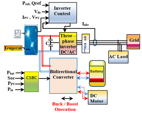
The proposed model shown in Figure 1, is composed of PVG (Pmax=252.4 kw), Battery energy storage, AC load supplied by a DC/AC converter, and DC motor connected between PVG and the Battery through bidirectional converter.
Figure 1. The proposed structure of the hybrid (PV-Battery-Grid) energy generation system
The bidirectional converter is an important one for energy storage, it is not only enhancing the efficiency, but it also protects the source from under change or over change. it is a dual functionality can be used in (boost) charge mode or (buck) discharge mode [7, 8]. Additionally, the DC-AC power converter is used to transfers and converts the available power at the DC side of a PVG into AC power at the grid side [9]. While, the CSBC Controller is in charge of maintains balance and stability by equalizing power between PVG source, battery storage and DC machine loads in grid-connected mode.
2.1 PV generator (PVG)
The character for non-linearity between current and voltage in a PV panel is deduced from Eq. (1) [10, 11]. Figure 2 shows the (I-V) and (P-V) characteristics of the PVG used in the simulation of the proposed model which consists of solar panels of the brand SPR-E19-410-COM modules.
Figure 2. The (P-V) and (I-V) characteristic curves for different irradiation values, and different temperature values
$I=N_{p} I_{P V}-N_{p} I_{0}\left(e^{\left(q\left(V+R_{s} \frac{I N_{s}}{N_{p}}\right) / A k T N_{s}\right)}-1\right)-\frac{V+\left(R_{s} I N_{s} / N_{p}\right)}{R_{p}+\left(N_{s} / N_{p}\right)}$ (1)
2.2 Bidirectional DC-DC converter (BDC)
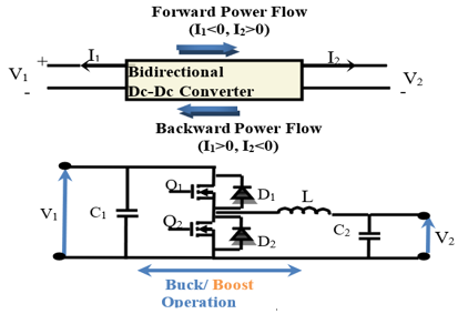
Figure 3 shows the circuit diagram of the basic non-isolated bidirectional DC-DC converter (BDC). It is a device for the purpose of step-up or step-down the voltage level with the capability of flow power in either forward directions or in backward direction [12].
The BDC provides the required bidirectional power flow for battery charging and discharging using two bidirectional switches like MOSFET’s or IGBT’s [13]. Table 1 below presents the possible operating cases of bidirectional converter, that they are summarized as follows [14, 15].
Figure 3. The circuit diagram of the BDC
Table 1. The possible operating cases of BDC
|
Case |
Switch Diode |
State |
Power flowing direction |
Voltage comparison |
Bidirectional Mode |
State of battery |
|
1 |
Q1 |
ON |
Forward |
Vin =V1(high-voltage side)>Vout =V2(low voltage-side) |
Buck |
Charging |
|
Q2 |
OFF |
|||||
|
D2 |
Active |
|||||
|
2 |
Q1 |
OFF |
Backward |
Vin =V2(low-voltage side)<Vout =V2(high-voltage side) |
Boost |
Discharging |
|
Q2 |
ON |
|||||
|
D1 |
Active |
Relationships between outputs and inputs (voltage-current) of BDC are determined as follows [16]:
Buck mode
$\frac{V_{1}}{V_{2}}=\frac{1}{D}$ (2)
Boost mode
$\frac{V_{1}}{V_{2}}=\frac{1}{1-D}$ (3)
where, D is the duty cycle equal to D=Ton/T, and switching period is D=Ton+Toff:
2.3 Storage system
Batteries store and release the excess energy produced electrochemically, which qualifies it as a guarantee a continuous power supply for loads. The equivalent circuit of the (Ni-MH) battery model, shown in Figure 4 used in [14] is simulated in this paper.
Figure 4. Battery of storage system
The Eq. (4) determines the relation between the parameters, which characterizes a battery:
$A . h_{\text {used }}=A . h \times\left(1-S o C_{(0)}\right)+\int \frac{\left(\left(V_{o c}-\sqrt{4 R_{i v}-P_{e l}}\right) / 2 R_{i v}\right)}{3600} d t$ (4)
where, A.hused is the nominal capacity used of battery, and Pel is the output electrical power of battery.
2.4 Three-phase inverter DC/AC
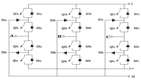
The presence of this inverter is important as it separates between PVG and grid; it consists of 03 arms of power switching devices. Each arm consists of 04 switching devices along with their anti-parallel diodes and two neutral clamping diodes as shown in the Figure 5 below [17, 18].
Figure 5. Three-phase inverter DC/AC
2.5 DC motor load
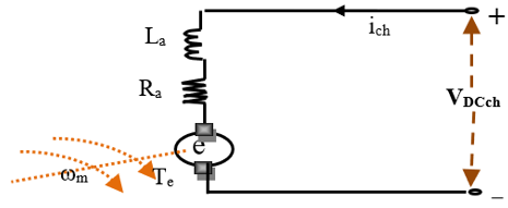
In the wound-field DC machine model, an RL circuit as shown in Figure 6 represents the field circuit, according to the following relationship [19]:
$\left\{\begin{array}{l}v_{D C c h}=e+R_{a} i_{c h}+L_{a} \frac{d i_{c h}}{d t}=e+R_{a} i_{c h} \\ e=K_{b} \omega_{m} \\ P_{e l-D C-c h}=v_{D C c h} i_{c h}=e i_{c h}+R_{a} i_{c h}^{2}\end{array}\right.$ (5)
where, e inducted electromagnetic force (emf); ωm speed and Kb constant machine.
Figure 6. Equivalent circuit of a dc motor
The control system is dividing by two parts as follows: (1) An Inverter control (IC); (2) A control strategy for bidirectional converter (CSBC).
3.1 Inverter control (IC)
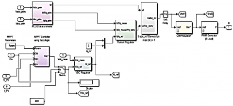
To control the electrical parameters of a DC-AC inverter, balancing of grid, and extract Maximum Power of PVG. we use the inverter control which consists of PLL & Measurements, DC Voltage Regulator, Current Regulator, MPPT (using fuzzy logic controller), and PWM Modulator as shown in Figure 7 [20, 21].
3.2 Maximum power point tracking (FLC)
Figure 8 shows the membership functions of the fuzzy logic controller (FLC) used to follow the MPPT.
3.3 Control strategy for bidirectional converter (CSBC)
In this work the connexion of a battery energy storage system with management Control Strategy optimized by PSO (particle swarm algorithm) For Bidirectional Converter, is required to maintain the stability, supply continuity and viability of the grid.
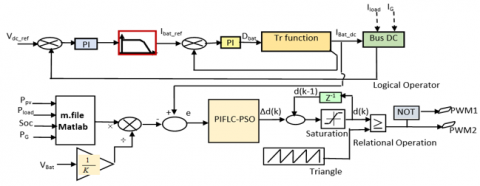
Figure 9. Intelligent control structure of BDC
The Figure 9 shows the structure adopted for control of buck-boost converter that allows a bidirectional flow of the electrical energy during charge/ discharge process of Battery. The reference value Ibat-ref that produced by dividing the power reference value Pbat_ref resulting from the power control unit by the Battery output voltage Vbat to generate the reference current [14]. Next, an FLC-PSO controller (PI type FLC tuning by PSO algorithm) regulate the current I-bat-mes to follow the reference signal in order to follow the reference signal. Ultimately, we get a command signal Δd(k) used to produce the appropriate switching pulses for the BDC.
The control-to-current transfer function can be obtained in (6). Eq. (6) tells us that this is a third-order power stage model [14].
$F_{\text {id }}=\frac{\hat{i}}{\bar{d}}=\frac{\left(s+\frac{1}{C_{1} R_{a}}\right) \cdot\left(s+\frac{1}{C_{2} R_{\mathrm{var}_{-} B a t}}\right) \cdot V_{p v}-\frac{D}{C_{1}} \cdot \frac{I_{L}}{L}\left(s+\frac{1}{C_{2} R_{\mathrm{var}_{-} B a t}}\right)}{s \cdot\left(s+\frac{1}{C_{1} R_{a}}\right) \cdot\left(s+\frac{1}{C_{2} R_{\mathrm{var}_{-} B at}}\right)+\frac{D^{2}\left(s+\frac{1}{C_{2} R_{\mathrm{var}_{-} B a t}}\right)}{L C_{1}}+\frac{\left(s+\frac{1}{C_{1} R_{a}}\right)}{L C_{2}}}$ (6)
3.4 PIFLC-PSO controller
This tuning method was proposed in Ref. [22]. It’s based on a PI controller that expressed in terms of fuzzy rules, in which a PSO algorithm is used to find for the optimal parameters in the fuzzy tuning rules. The Figure 10 shows a PIFLC-PSO controller topology.
Figure 10. Block diagram for the PIFLC-PSO controller
The relation that can be defined as the equation of the PIFLC it’s the derivative on both sides of classical PI equation (7):
$\left\{\begin{array}{l}u=k_{p} e+k_{i} \int_{0}^{t} e d t \\ \Delta u=k_{p} \Delta e+k_{i} e\end{array}\right.$ (7)
In comparison with conventional PI controller, Kp and KI can be assumed as fuzzy gains or scale factors of FLC [22].
In Figure 10, as shows Block diagram where fuzzy variables before applying to the fuzzy block and fuzzy output variables are multiplied by the scaling factors (G0, G1, and G2) in Eq. (8), with tuning of output scaling factor G2 using PSO algorithm [22, 23].
$\left\{\begin{array}{l}E(k)=G_{0} e(k) \\ \Delta E(k)=G_{1}\left(\frac{e(k)-e(k-1)}{T}\right) \\ d(k)=d(k-1)+G_{2} \Delta d(k)\end{array}\right.$ (8)
In this work, Mamdani fuzzy inference system with two inputs and one output is proposed as showed in Plot surface input/output in the Figure 11. Then, scaling the output factor (G2) was performed using Particle Swarm Optimization (PSO) algorithm that estimates the optimal variable through iterations by minimizing of a cost function. Eq. (9) and (10) presents performance index equation in continuous-time (JC) and discrete-time (JD), respectively [22, 23].
$\left\{\begin{array}{l}J_{C}=k \int|e(t)| d t \\ e(t)=I_{b a t_{-} r e f}-I_{b a t_{-} d c}(t) \\ t \in\left[0, t_{1}\right]\end{array}\right.$ (9)
$\left\{\begin{array}{l}J_{D}=k \sum_{i=1}^{k}|e(i)| \\ e[k]=I_{b a t_{-} \text {ref }}-I_{b a t_{-} d c}[k] \\ k=1,2, \ldots, \text { iter max }\end{array}\right.$ (10)
3.5 Using PSO algorithm for scaling G2
PSO algorithm is an evolutionary computation technique, based on the swarm behaviour of the birds in nature. He has been applied to almost in every area in optimization and computational intelligence. The algorithm guides the optimization search through cooperation and competition between particles producing swarm intelligence [21, 22]. Individuals called particles, being each particle a possible solution of the problem, form the population. Eq. (11) govern the next position and velocity term of the particle [24, 25].
Equations the PSO algorithm [21-23]:
$\left\{\begin{array}{l}x_{i}^{(k+1)}=x_{i}^{(k)}+v_{i}^{(k+1)} \\ v_{i}^{(k+1)}=w(k) \cdot v_{i}^{(k)}+c_{1} \cdot r \cdot\left(x_{\text {pbesti }}^{k}-x_{i}^{(k)}\right)+c_{2} \cdot r \cdot\left(x_{\text {gbesti }}^{k}-x_{i}^{(k)}\right) \\ w(k)=w_{\max }-\left(\frac{w_{\max }-w_{\min }}{k_{\max }}\right) \cdot k \\ F(k)=\sum_{i=1}^{N}|e(i)| \\ k=1,2,3, \ldots \ldots, n\end{array}\right.$ (11)
where, $x_{i}^{k}$: Position of ith particle; $v_{i}{ }^{k}$: Velocity of ith particle; Pbest: Individual best position; k: Number of iterations; Gbest: Best position reached by the particles of the swarm; w: Inertia term is calculated by Eq. (11); F(k): Fitness function; r: Random generated number with a range of [0, 1].
The main structure of algorithm is:
Set the initial random particles, pbest, gbest, xpbest and xgbest
For each interaction k;
Update inertia weights by Eq. (11)
For each particle i of the population
Update velocities and position of all particle at iteration k using Eq. (11)
Evaluate the fitness of all particles.
If fitness (x (i)) <pbest (i) then update xpbest and pbest
xpbest=x(i);
pbest=fitness (x (i))
If pbest<gbest then update xgbest and gbest
xgbest=xpbest;
gbest=pbest;
Next particle
Next iteration
xgbest is the solution
In this work, the parameters for PSO algorithm using in simulation are show in Table 2.
Table 2. The parameters of PSO algorithm
|
Parameter |
Symbol |
Value |
|
Swarm Coefficients |
c1, c2 |
2.05 |
|
Min weighting coefficient |
wmin |
0.4 |
|
Max weighting coefficient |
wmax |
0.9 |
|
Iteration |
k |
50 |
|
Swarm size |
n |
25 |
|
Lower bound of variables |
$\Delta d(k)_{\min }$ |
[-0.15 -0.148] |
|
Upper bound of variable |
$\Delta d(k)_{\max }$ |
[0.15 0.151] |
Figure 11. Plot surface input/output FLC [E(k), ΔE(k)] and Δd(k)
As shown in the Figure 12, the whole work implemented under Mat-lab/ Simulink software. Here, the performance of PV generator, DC-AC converter, Bidirectional buck-boost converter, battery, Grid connection, DC Motor load, are taken and also our performance is compared by using two techniques of control PI and PIFLC-PSO.
Figure 12. The model simulation
Figure 13. Solar irradiance
The above diagram (Figure 13) represents the solar radiation applied to the PV panels, which changes gradually between 200 and 800 w/m².
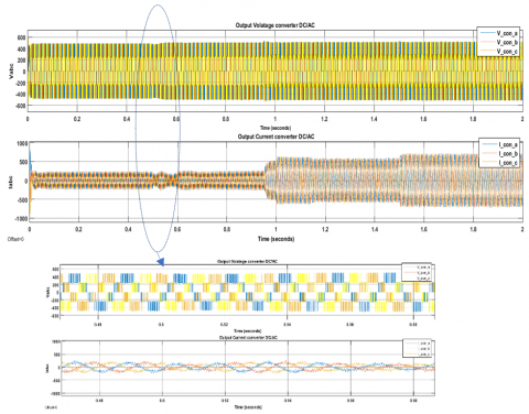
Figure 14. Output voltage and current DC-AC converter
Figure 14 shown an output voltage and current of DC/AC Boost converter that connects the PV generator with the grid. During the change of Irradiance, the output AC current also change.
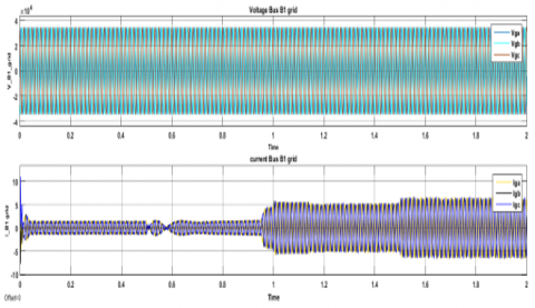
Figure 15. Grid voltage and current source
Figure 16 shows that the delivered photovoltaic power is more stable when not using a smart controller (PI-FLC-PSO) comparing by the classic regulation (PI), this can be seen by zooming the intervals [1.56-1.7] and [2.42-2.52]
The below graph (Figure 17) indicates the comparative analysis of the state of charge Battery (Soc %). The plot is compared in both cases when using the PI controller and PI-FLC PSO controller. This result shows that the minimum value of Soc in the PI-FLC PSO control increases by 0.015% over the other case, taking the same conditions for the proposed system. This slight improvement in the state of charge (Soc%) is due to the rapid search for optimal solution (value of the output-scaling factor G2) obtained after the calculation of the PSO algorithm this is what accelerates the obtaining the optimal switching angles which act on the bidirectional converter.
Figure 16. Output PV power
Figure 17. State of charge Battery (SOS %)
The Figure 18 represents the voltage DC Bus Vdc, it shows that the PI-FLCPSO has successfully stabilize the DC-link voltage at the reference value (500 V), compared to the other controller, despite the change in solar radiation shown in Figure 13.
Figure 18. Voltage DC Bus (Vdc)
The plot below (Figure 19) indicates the comparative analysis of the speed DC motor in both cases of control (PI &PIFLC PSO). This comparison shows that the response is rapid and the speed is maintained stable when using a PI FLC controller tuning with PSO algorithm, the delay time between them is equal 0.05 sec.
Figure 19. Speed DC Motor load
In this paper, an intelligent control strategy for a bidirectional DC-DC converter based on the FLC tuned by PSO are proposed in the management the energy flows in the grid-connected photovoltaic Battery storage system. this strategy is implemented and evaluated in the Matlab/Simulink environment.
The optimal value of the output-scaling factor for the PIFLC was calculated applying PSO algorithm, this allows ensuring adaptive regulation of the output currents of the DC motor load and stabilizes the DC link voltage of DC/AC converter and DC/DC bidirectional converter. This is what we observed through the results obtained, we say that the proposed control provided the system with the stability of Vdc voltage, and also contributed to improving the speed of response in the consumption required by the DC motor load.
In perspective of this work, this control Simulink model proposed to better manage the circulation of power flow in hybrid systems (PV/Battery-grid) must be executed on dSPACE platforms to experimentally verify its effectiveness, in very variable weather conditions.
[1] Arani, A.K., Gharehpetian, G.B., Abedi, M. (2019). Review on energy storage systems control methods in microgrids. International Journal of Electrical Power & Energy Systems, 107: 745-757. https://doi.org/10.1016/j.ijepes.2018.12.040
[2] Awasthi, A., Karthikeyan, V., Das, V., Rajasekar, S., Singh, A.K. (2017). Energy storage systems in solar-wind hybrid renewable systems. In Smart Energy Grid Design for Island Countries, pp. 189-222. https://doi.org/10.1007/978-3-319-50197-0_7
[3] Yi, Z., Dong, W., Etemadi, A.H. (2017). A unified control and power management scheme for PV-battery-based hybrid microgrids for both grid-connected and islanded modes. IEEE Transactions on Smart Grid, 9(6): 5975-5985. https://doi.org/10.1109/TSG.2017.2700332
[4] Ansari, S., Ayob, A., Lipu, M.S.H., Saad, M.H.M., Hussain, A. (2021). A review of monitoring technologies for solar PV systems using data processing modules and transmission protocols: Progress, challenges and prospects. Sustainability, 13(15): 8120. https://doi.org/10.3390/su13158120
[5] Mirzaei, A., Forooghi, M., Ghadimi, A.A., Abolmasoumi, A.H., Riahi, M.R. (2017). Design and construction of a charge controller for stand-alone PV/battery hybrid system by using a new control strategy and power management. Solar Energy, 149: 132-144. https://doi.org/10.1016/j.solener.2017.03.046
[6] Rajasekaran, R., Rani, P.U. (2021). Bidirectional DC-DC converter for microgrid in energy management system. International Journal of Electronics, 108(2): 322-343. https://doi.org/10.1080/002-07217.2020.1793418
[7] Randive, V., Wandhare, R. (2020). Simplified state-space average model and control strategy for the dual active bridge power converter. In 2020 IEEE 9th Power India International Conference (PIICON), Sonepat, India, pp. 1-6. https://doi.org/10.1109/PIICON49524.2020.9113063
[8] Rajanna, B.V., Lalitha, S.V.N.L., Rao, G.J., Shrivastava, S.K. (2016). Solar photovoltaic generators with MPPT and battery storage in microgrids. International Journal of Power Electronics and Drive Systems, 7(3): 701-712. https://doi.org/10.11591/ijpeds.v7.i3.pp701-712
[9] Raj, A., Gopinath, A. (2015). Proportional plus Integral (PI) control for maximum power point tracking in photovoltaic systems. International Research Journal of Engineering and Technology (IRJET), 2(6): 408-412. https://doi.org/10.3390/su13052562
[10] Praiselin, W.J., Edward, J.B. (2017). Voltage profile improvement of solar PV grid–connected inverter with micro grid operation using PI controller. Energy Procedia, 117: 104-111. https://doi.org/10.1016/j.egy-pro.2017.05.112
[11] Gokul, K.K., Emmanuel, B.P., Ashok, S., Kumaravel, S. (2017). Design and control of non-isolated bidirectional DC-DC converter for energy storage application. In 2017 2nd IEEE International Conference on Recent Trends in Electronics, Information & Communication Technology (RTEICT), Bangalore, India, pp. 289-293. https://doi.org/10.1109/RTEICT.2017.8256603
[12] Song, M.S., Son, Y.D., Lee, K.H. (2014). Non-isolated bidirectional soft-switching SEPIC/ZETA converter with reduced ripple currents. Journal of Power Electronics, 14(4): 649-660. https://doi.or-g/10.6113/JPE.2014.14.4.649
[13] Chettibi, N., Mellit, A. (2018). Intelligent control strategy for a grid connected PV/SOFC/BESS energy generation system. Energy, 147: 239-262. https://doi.org/10.1016/j.energy.2018.01.030
[14] Karthikeyan, V., Gupta, R. (2017). Varying phase angle control in isolated bidirectional DC–DC converter for integrating battery storage and solar PV system in standalone mode. IET Power Electronics, 10(4): 471-479. https://doi.org/10.1049/iet-pel.2016.0162
[15] Lakhdara, A., Bahi, T., Moussaoui, A.K. (2020). Control and management solar-wind-storage hybrid system. In International Conference in Artificial Intelligence in Renewable Energetic Systems, pp. 3-14. https://doi.org/10.1007/978-3-030-63846-7_1
[16] Menadi, A., Abdeddaim, S., Ghamri, A., Betka, A. (2015). Implementation of fuzzy-sliding mode based control of a grid connected photovoltaic system. ISA Transactions, 58: 586-594. https://doi.org/10.1016/j.isatra.2015.06.009
[17] Boumaaraf, H., Talha, A., Bouhali, O. (2015). A three-phase NPC grid-connected inverter for photovoltaic applications using neural network MPPT. Renewable and Sustainable Energy Reviews, 49: 1171-1179 https://doi.org/10.1016/j.rser.2015.04.066
[18] Dilmi, I., Bouguerra, A., Djrioui, A. (2020). Interval Type-2 fuzzy logic-second order sliding mode based fault detection and active fault-tolerant control of brushless DC motor. Journal Européen des Systèmes Automatisés (IIETA), 54(3): 475-485. https://doi.or-g/10.18280/jesa.540311
[19] Hu, J., Xu, Y., Cheng, K.W., Guerrero, J.M. (2018). A model predictive control strategy of PV-Battery microgrid under variable power generations and load conditions. Applied Energy, 221: 195-203. https://doi.org/10.1016/j.apener-gy.2018.03.085
[20] Boudechiche, M., Sarra, M., Gaubert, J.P. (2020). Anti-windup FOPID-based DPC for SAPF interconnected to a PV system tuned using PSO algorithm. European Journal of Electrical Engineering (EJEE), 22(4-5): 313-324. https://doi.org/10.18280/ejee.224-503
[21] Firdaus, A.A., Yunardi, R.T., Agustin, E.I., Nahdliyah, S.D., Nugroho, T.A. (2020). An improved control for MPPT based on FL-PSO to minimize oscillation in photovoltaic system. International Journal of Power Electronics and Drive Systems, 11(2): 1082. https://doi.org/10.11591/ijpeds.v11.i2.pp1082-1087
[22] Erdem, H., Altinoz, O.T. (2016). Tuning of output scaling factor in PI-like fuzzy controllers for power converters using PSO. Journal of Intelligent & Fuzzy Systems, 30(5): 2677-2688. https://doi.org/10.3233/IFS-152020
[23] Bengourina, M.R., Rahli, M., Saadi, S., Hassaine, L. (2018). PSO based direct power control for a multifunctional grid connected photovoltaic system. International Journal of Power Electronics and Drive System (IJPEDS), 9(2): 610-621. https://doi.org/10.11591/ijpeds.v9n2.pp610-621
[24] Sánchez-Vargas, O., Estefany, S., Aguayo-Alquicira, J (2021). Evolutionary metaheuristic methods applied to minimize the THD in inverters: A systematic review. European Journal of Electrical Engineering (EJEE), 23(3): 237-245A. https://doi.org/10.18280/ejee.230308
[25] Bouallègue, S., Haggège, J., Ayadi, M., Benrejeb, M. (2012). PID-type fuzzy logic controller tuning based on particle swarm optimization. Engineering Applications of Artificial Intelligence, 25(3): 484-493. https://doi.org/10.1016/j.engappai.2011.09.018