Fares Zaamouche* | Salah Saad | Larbi Hamiche
© 2020 IIETA. This article is published by IIETA and is licensed under the CC BY 4.0 license (http://creativecommons.org/licenses/by/4.0/).
OPEN ACCESS
Among the renewable energy sources, solar energy has been a big part interest sources in past few years. With the development of power electronics technology, the multi-level inverters are widely used for the production of electrical energy. There are several variants of these converters, the cascaded-H bridge multi-level inverter (CHB) is more advantageous compared to the other arrangements, since each H bridge inverter has an independent DC source. In this paper, a three-phase five-level CHB inverter feeding by a PV solar-Boost converter system using a discontinuous pulse width modulation (DPWM) presented, improved the power quality by reducing the total harmonic distortion (THD) at the outputs voltage and current and also reducing inverter switching losses. The main idea of this work, is that the DPWM technique is used, studied and analyzed in detail to control the multilevel inverters topologies, and it can have many advantages to the other PWM techniques like space vector modulation (SVPWM). The simulation was performed in the MATLAB/Simulink software using an induction machine like a load and the obtained results are presented and analyzed.
cascaded inverter, boost converter, discontinuous modulation, switching losses
Among the renewable energy sources, solar energy has been a big part interest sources in past few years. It is unpolluted and economics. It offers many advantages such as, it is unpolluted and economics, it requires easy and simple maintenance interventions [1, 2].
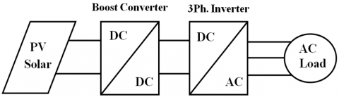
The electrical energy produced by a PV system, is characterized by the sunshine rate, the temperature and the voltage of each PV module. For low power applications, the electrical energy produced can be supplied directly to the load. So, for high and medium power applications, the static converters must be used as an intermediate interface between the PV modules and the load (or the electrical network) [3]. For AC loads, the static converter can be represented by a combination of a DC/DC boost chopper and a DC/AC voltage source inverter (VSI) as in Figure 1.
Figure 1. Energy conversion scheme
The major drawback of the VSI is the not perfectly sinusoidal current and voltages at its output which influences on the operating regime of the loads. These current and voltage waveforms are rich in harmonics presenting a great issue in the field of electrical engineering.
As part of the research methods of reducing harmonics, several studies were made on two axes. The first is the use of multilevel topologies of the inverter (like NPC, Cascade and Hybrid, etc.), while the second focuses on controlling the opening and closing of the semiconductors forming the inverter by pulse width modulation technique (like Sinusoidal PWM, Space vector PWM and Discontinuous PWM, etc.). There are several works [4-7] have studied and treated the two modulation strategies, such as a sinusoidal PWM and a space vector PWM, with details. But there are fewer papers that analyze the application of the discontinuous DPWM strategy on multilevel inverters.
The objective of these PWM strategies is to ensure better control of the inverter and to acquire better values, such as the harmonic rate (THD), the number of switching and the torque ripples in the AC systems drives. In high power applications, the multilevel structure is more suitable, compared to the two-level structure, because the voltages and currents exit rates are much lower harmonic distortion.
In this paper, the proposed discontinuous PWM strategy for the control a three phase five-level cascaded H-bridge (CHB) inverter fed by a PV system was simulated in the MATLAB/Simulink environment. As well, the test is done to order a squirrel cage asynchronous machine of 1.5kw in scalar control. The obtained results are very encouraging and have showed that DPWM technique has high performances in harmonics current (THD), the number of closing and opening of the switches is reduced, which gives minimization of the switching losses and a great stability to the motor.
This work has been divided into six parts as follows: After the introduction in the first part. The second part explains the PV solar and boost converter basics. The third part provides an overview of five-level CHB inverter topology. DPWM is shown in the 4th part. The 5th part presents the simulation, discussion and interpretation results, that validate the algorithms and the schemes used in this work. Conclusion is made in the last part.
2.1 PV module
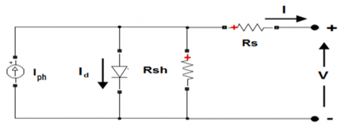
The basic structure of the solar cell is represented by a P/N semiconductor in Figure 2. There are many works [8, 9] have studied and developed the mathematic model of PV cell.
Figure 2. The PV block array
The output current of the PV is:
$I=I_{p h}-I_{s}\left(e^{\frac{q\left(V+I . R_{s}\right)}{A . k . T}}-1\right)-\frac{V+I . R_{s}}{R_{s h}}$ (1)
where,
V represent the output voltage.
Iph is photon current and Rsh is shunt resistance.
Id is diode current and Is (Isc) is diode saturation current.
q is the electronic charge, q = 1,602 x 10-19 C
k is the Boltzman constant, k = 1,381 x 10-23
A is PN junction ideality factor.
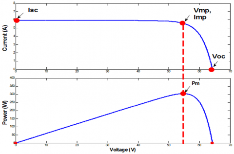
The characteristic of the output power as shown in Figure 3.
Figure 3. Characteristics of the PV array
Imp, Vmp and Pm are the maximum point of the current, the voltage and the power respectively.
2.2 DC-DC boost converter
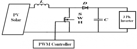
To obtain the maximum power from the panel, a DC/DC boost converter is used. It's the interface that allows adaptation between the PV panel and the inverter. The topology of this converter is shown in Figure 4. In the technical literature we can find many papers on the design of this converter like [10-14].
Figure 4. DC/DC boost converter connected between PV panel and the three-phase inverter
The equation which determines the output voltage is as follows:
$V_{\text {out }}=\frac{1}{1-\alpha} V_{\mathrm{pv}}$ (2)
where,
Vpv is the voltage input (solar panel).
α is the duty cycle for the switching device, and therefore
$\alpha=\frac{t_{O N}}{T}$ (3)
T is the sample period of the boost converter, T = 1/fsw and T = TON + TOFF
TON is the time when the switch is closed.
TOFF is the time when the switch is opened.
A VSI is a power static converter, which generates a sinusoidal AC output from a DC input. In our work a three phase five-level CHB is used as an interface between PV solar/DC-DC boost converter and AC drive system. Thus, it is necessary to present a description of this inverter.
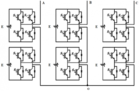
Figure 5 illustrates the topology of a three-phase five-level CHB inverter used in this work. It is composed of three arms. Each arm is build of one phase full bridge that is assembled in chain [15, 16]. Each bridge consists of four IGBTs, four diodes in anti-parallel are mounted on each switch and one independent voltage source E.
Figure 5. A topology of a three-phase five-level CHB inverter
The output phase voltage of this topology is synthesized by the addition of the voltages that are generated by different combinations of the eight switches, (S1, S2, S3, and S4) for the upper bridge [17, 18], and (S1, S2, S3, and S4) for the lower bridge, as given in Table 1.
Table 1. A single-phase five-level CHB inverter functioning’s principle
|
The upper bridge |
The lower bridge |
Vao (v) |
||||||
|
S1 |
S2 |
S3 |
S4 |
S1 |
S2 |
S3 |
S4 |
|
|
1 |
0 |
0 |
1 |
1 |
0 |
0 |
1 |
2E |
|
1 |
1 |
0 |
0 |
1 |
0 |
0 |
1 |
E |
|
1 |
0 |
0 |
1 |
0 |
0 |
1 |
1 |
E |
|
1 |
0 |
0 |
1 |
1 |
1 |
0 |
0 |
E |
|
0 |
0 |
1 |
1 |
1 |
0 |
0 |
1 |
E |
|
1 |
1 |
0 |
0 |
1 |
1 |
0 |
0 |
0 |
|
1 |
1 |
0 |
0 |
0 |
0 |
1 |
1 |
0 |
|
1 |
0 |
0 |
1 |
0 |
1 |
1 |
0 |
0 |
|
0 |
1 |
1 |
0 |
1 |
0 |
0 |
1 |
0 |
|
0 |
0 |
1 |
1 |
1 |
1 |
0 |
0 |
0 |
|
0 |
0 |
1 |
1 |
0 |
0 |
1 |
1 |
0 |
|
0 |
1 |
1 |
0 |
1 |
1 |
0 |
0 |
-E |
|
0 |
0 |
1 |
1 |
0 |
1 |
1 |
0 |
-E |
|
0 |
1 |
1 |
0 |
0 |
0 |
1 |
1 |
-E |
|
1 |
1 |
0 |
0 |
0 |
1 |
1 |
0 |
-E |
|
0 |
1 |
1 |
0 |
0 |
1 |
1 |
0 |
-2E |
where,
State 1 shows that the switch is closed
State 0 shows that the switch is opened
With the development of the digital electronics, and as part of the research methods of reducing harmonics and switching losses, several studies were made on controlling the opening and closing of the semiconductors forming the inverter by pulse width modulation technique (like Sinusoidal PWM, Space vector PWM and Discontinuous PWM, etc.) [19-21]. There are several works have studied and treated the two modulation strategies, such as a SPWM and a SVPWM, with details. But there are fewer papers that analyze the application of the discontinuous DPWM strategy on multilevel inverters. It uses the space-vector concept to compute the duty cycle of the switches. It can be observed that in SVPWM technique, the periods of use of zero vectors T0 and T7 are equal, therefore a factor corresponding to a distribution of these periods is defined as follows:
$\mathrm{K}=\frac{\mathrm{T}_{7}}{\left(\mathrm{T}_{0}+\mathrm{T}_{7}\right)}$ (4)
The main idea of this strategy is to satiate the reference wave for 2π/3 during the electrical period, which leads in, a discontinuity between the three arms of the inverter, and consequently, a minimization of the number of switching operations [19]. According to the choice of the location of this satiate, there are six different techniques of the DPWM modulation, and they can be subdivided into three groups as shown in Table 2.
Table 2. A various strategies of DPWM
|
Saturations |
Interval |
Techniques |
Location |
|
Once |
2π/3 |
DPWM_MIN |
at -1 |
|
DPWM_MAX |
at +1 |
||
|
Twice |
π/3 |
DPWM_0 |
Late by π/6 |
|
DPWM_1 |
with 0 radian |
||
|
DPWM_2 |
Advance by π/6 |
||
|
Four times |
π/6 |
DPWM_3 |
at -1 and at +1 |
where,
+1 is OFF at upper state, or
-1 is OFF at lower state.
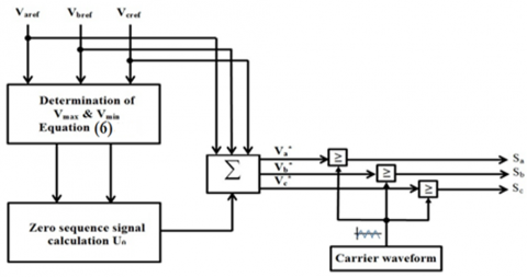
Figure 6 shows the basic principle of DPWM strategy, this method is based on the injection of the homopolar components U0 in reference waves [22, 23].
Figure 6. The principle scheme of the DPWM
with:
$\left\{\begin{array}{l}\mathrm{V}_{\operatorname{aref}}(\mathrm{t})=\mathrm{M} \sin \omega \mathrm{t} \\ \mathrm{v}_{\mathrm{bref}}(\mathrm{t})=\operatorname{Msin}\left(\omega \mathrm{t}-\frac{2 \pi}{3}\right) \\ \mathrm{v}_{\mathrm{cref}}(\mathrm{t})=\operatorname{Msin}\left(\omega \mathrm{t}-\frac{4 \pi}{3}\right)\end{array}\right.$ (5)
$\left\{\begin{array}{l}V_{\max }=\operatorname{Max}\left(V_{\text {aref }}, V_{\text {bref }}, V_{\text {cref }}\right) \\ V_{\min }=\operatorname{Min}\left(V_{\text {aref }}, V_{\text {bref }}, V_{\text {cref }}\right) \\ V_{\text {med }}=\operatorname{Med}\left(V_{\text {aref }}, V_{\text {bref }}, V_{\text {cref }}\right)\end{array}\right.$ (6)
Figure 7 presents all waveforms of the DPWM, SPWM and SVPWM strategies.
According to the Eq. (4), the expression of the homopolar components is given in Table 3, for each modulation techniques.
Table 3. The expression of the homopolar components
|
Strategies |
Zero vectors utilisation |
K |
Homopolar components |
|
SVPWM |
T0 = T7 |
0.5 |
U0 = - (Vmax + Vmin)/2 |
|
DPWM_MIN |
T0 = Tz and T7 = 0 |
0 |
U0 = - (Vmin + E/2) |
|
DPWM_MAX |
T0 = 0 and T7 = Tz |
1 |
U0 = - (Vmax - E/2) |
|
DPWM_0, DPWM_1, DPWM_2 and DPWM_3 |
T0 and T7 are variables |
0÷1 |
$\mathrm{U}_{0}$ $=-\left(\mathrm{KV}_{\max }\right.$ $+(1-\mathrm{K}) \mathrm{V}_{\min }$ $\left.+(1-2 \mathrm{K}) \frac{\mathrm{E}}{2}\right)$ |
Figure 7. The reference waveforms
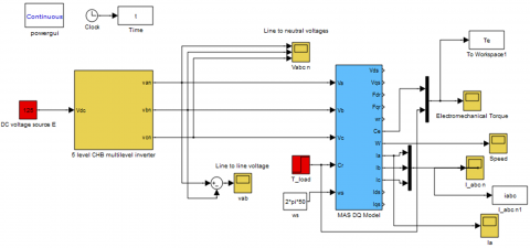
Figure 8. The scheme of 3-ph. five-level CHB inverter fed Induction motor
In order to applicate and contrast the developed methods computer simulations were used on a three phase five-level CHB inverter feeding 1.5 KW asynchronous motor in open loop.
In our work, we carried out the simulation in two parts:
- Firstly, we consider that the inverter is not supplied by the PV solar-Boost converter, and the supply voltage is represented by a DC voltage source with a value of E=125 V.
- Secondly, we simulated the complete system: PV solar-Boost converter-five-level CHB inverter-Induction machine.
The asynchronous motor parameters are given in Table 4. At t=1.2 s a load torque of Tload = 7 N.m is applied to the motor shaft. We took a modulation index value M= 0.9 and a commutation frequency is 6 KHz.
Table 4. Asynchronous motor parameters
|
|
Parameters |
|
Electromagnetic |
Vab= 380 V, f=50 Hz, In= 3.6 A Rs=4.85Ω, Rr=3.085 Ω, Ls= Lr=0.274H, M=0.258 H, |
|
Mechanical |
P=1.5 Kw, and n=1400 tr.mn-1. f=0.00114Nm.rad-1.s-1, J=0.031 Kgm2 and Tr=3N.m |
5.1 Three phase five-level CHB inverter fed Induction motor
In this section, we have based on the comparison between SVPWM with DPWM, since several works discuss the application of the SVPWM technique on multilevel inverters as a strategy for controlling the opening and the closing of semiconductors [24, 25]. The scheme is modeled in MATLAB using Simulink tools as shown in Figure 8.
The obtained waveforms are presented in Figure 9 to Figure 16 for SVPWM and DPWM_3. Whereas the waveforms of DPWM_MIN, DPWM_MAX, DPWM_0, DPWM_1 and DPWM_2 are not presented, but the simulation results of these strategies are shown and summarized in Table 5.
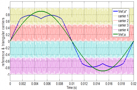
Figure 9. The reference waveforms and triangular carriers for SVPWM techniques, with M = 0.9
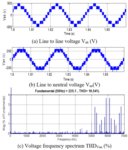
Figure 10. Output voltages waveform with SVPWM
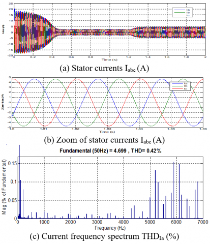
Figure 11. Output currents waveform with SVPWM
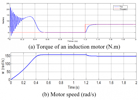
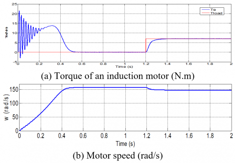
Figure 12. Torque and speed response with SVPWM
Figure 13. The reference waveforms and triangular carriers of DPWM_3 techniques, with M = 0.9
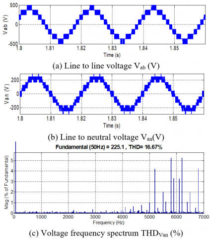
Figure 14. Output voltages waveform with DPWM_3
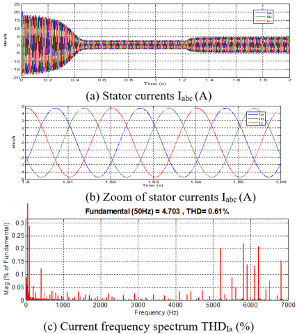
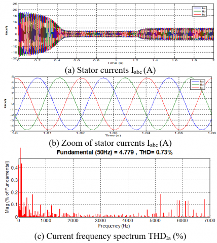
Figure 15. Output currents waveform with DPWM_3
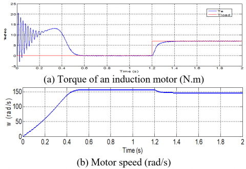
Figure 16. Torque and speed response with DPWM_3
Table 5. Simulation results
|
Techniques |
M=0.9 |
||
|
THDU (%) |
THDI (%) |
p |
|
|
DPWM_MIN |
16.81 |
0.72 |
72 |
|
DPWM_MAX |
16.81 |
0.72 |
73 |
|
SVPWM |
16.54 |
0.42 |
120 |
|
DPWM_1 |
16.73 |
0.67 |
76 |
|
DPWM_2 |
17.25 |
0.99 |
78 |
|
DPWM_3 |
16.67 |
0.61 |
73 |
|
DPWM_0 |
17.54 |
1.10 |
78 |
Width, p: is the total number of commutations in one period, for a single arm of the inverter.
The results of the developed algorithms of a three phase five-level CHB inverter feeding asynchronous motor are illustrated in Figure 9 to Figure 12 for SVPWM and Figure 13 to Figure16 for DPWM_3.
The Figure 9 and Figure 13 present the reference waveforms to generate the different pulses of the switches. Figure 10 and Figure 14 illustrate the voltage waveforms and their frequency spectrum. Figure 11 and Figure 15 have shown the phase current waveforms and their frequency spectrum. Figure 12 and Figure 16 illustrate the mechanical parameters of the induction motor, such as the torque ripples and the speed curves.
We noted from the voltage curves, that the number of switches operations p is very high (120 commutations in one period) when SVPWM is employed but the number of commutations is considerably minimized (73 commutations) when DPWM_3 is used, which leads to a reduction of 39.16% in switching losses, because we employed a value of 6 kHz as a switching frequency [26].
The total harmonic distortion (THDv) of voltage waveforms is 16.54 % and 16.67 % for SVPWM and DPWM_3 respectively. One can notice that the voltage THD of DPWM_3 is a little higher than the voltage THD of SVPWM.
The (THDI) of current waveforms is 0.42 % and 0.61 % for SVPWM and DPWM_3 respectively. We also have the current harmonic distortion is slightly higher when DPWM_3 is used.
Regarding the curves of the electromagnetic torque for the two strategies, it is noted that there is no deference between these characteristics obtained, with less fluctuations or ripples, and which gives the motor great stability, because the current at the output of the inverter has a sinusoidal form.
The torque and the speed curves have three sections: firstly a transient period from 0 to 0.5 s, secondly a no-load operation period (Tload=0 N.m) of 0.5 to 1.2 s and finally a load operation period (Tload=7 N.m) applied to 1.2 s until the end of the simulation time.
5.2 Three phase five-level CHB inverter fed Induction motor connected a PV solar-Boost converter
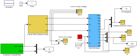
In this section, we have used DPWM_3 technique to control of the multilevel inverter, with consideration of the PV solar-boost converter. The latter is controlled by the PWM strategy with a hash frequency of 5 kHz. The scheme is modeled in MATLAB using Simulink tools as shown in Figure 17.
The obtained waveforms are presented in Figure 18 to Figure 21 for DPWM_3.
Figure 17. The scheme of 3-ph. five-level CHB inverter connected between a PV solar system and an Induction motor
Figure 18. The voltage output of the PV solar-Boost converter
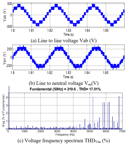
Figure 19. Output voltages waveform with DPWM_3
Figure 20. Output currents waveform with DPWM_3
The THD of voltage and current waveforms are (THDv=17.01%) and (THDI=0.73%) for DPWM_3 respectively. These values are slightly higher compared to those obtained when a supply voltage of the inverter is perfectly stabilized (THDv=16.67% and THDI=0.61%).
The simulation results are in good agreement in energy quality, the minimization of the switching losses and less torque ondulations can be obtained when DPWM-3 is employed for a 3-ph. five-level CHB inverter feeding AC machines. And by comparing these results with the results of the literature, it can be noted that the current and voltage waveforms are well acceptable under the IEEE recommendations.
Figure 21. Torque and speed response with DPWM_3
In the present study, a complete simulation system of a three-phase five-level cascaded-H Bridge inverter feeding by a PV solar-Boost converter has been proposed using MATLAB/Simulink environment. This topology of the inverter has more advantages than the standard two-level inverter.
The simulation results prove that this inverter topology controlled by a DPWM_3 strategy, the low order harmonics and the switching losses are substantially reduced (THDv=17.01%, THDI=0.73% and a reduction by 39.16% of switching losses). Hence, we could obtain the improved performance of the system. So, this topology is well suited for AC variable speed drives and for grid connected applications with additional closed loop regulations.
In the perspectives, we were interested in the implementation of this system in a microprocessor like the dSPACE DS1104 card in experimental platform.
[1] Ogbonnayaa, C., Turana, A., Abeykoonb, C. (2019). Energy and exergy efficiencies enhancement analysis of integrated photovoltaic-based energy systems. Journal of Energy Storage, 26: 1-13. https://doi.org/10.1016/j.est.2019.101029
[2] Nakayama, H., Hiraki, E., Tanaka, T., Koda, N., Takahashi, N., Noda, S. (2008). Stand-alone photovoltaic generation system with combined storage using lead battery and EDLC. 13th International Power Electronics and Motion Control Conference, Poznan, pp. 1877-1883. https://doi.org/10.1109/EPEPEMC.2008.4635539
[3] Salas, V., Barrado, A., Lazaro, A. (2006). Review of the maximum power point tracking algorithms for stand-alone photovoltaic systems. Solar Energy Materials & Solar Cells, 90(11): 1555-1578. https://doi.org/10.1016/j.solmat.2005.10.023
[4] Shete, P.S., Kanojiya, R.G., Maurya, N.S. (2012). Performance of sinusoidal pulse width modulation based three phase inverter. IJCA Proceedings on International Conference on Emerging Frontiers in Technology for Rural Area (EFITRA), pp. 22-26.
[5] Samiotis, E.A., Trigonidis, D.T., Vokas, G.A., Papageorgas, P., Anastasiadis, A.G. (2019). Simulation and implementation of a SPWM inverter pulse generator circuit for educational purposes. Energy Procedia, 157: 594-601. https://doi.org/10.1016/j.egypro.2018.11.224
[6] Shriwastava, R.G., Daigavane, M.B., Daigavane, P.M. (2016). Simulation analysis of three level diode clamped multilevel inverter fed PMSM drive using carrier based space vector pulse width modulation (CB-SVPWM). Procedia Computer Science, 79: 616-623. https://doi.org/10.1016/j.procs.2016.03.078
[7] Lang, B., Miao, M., Liu, W., Luo, G. (2009). Simulation and experiment study of space vector pulse width modulation. 9th Inter. Conf. on electronic measurement and Instruments ICEMI’09, Beijing, pp. 1-408/1-412. https://doi.org/10.1109/ICEMI.2009.5274842
[8] Oladimeji, I., Yahaya, N.Z., Saad, N., Umar, M.W. (2015). Matlab/Simulink model of solar PV array with perturb and observe MPPT for maximising PV array efficiency. IEEE Conference on Energy Conversion (CENCON), Johor Bahru, pp. 254-258. https://doi.org/10.1109/CENCON.2015.7409549
[9] Esram, T., Chapman, P.L. (2007). Comparison of photovoltaic array maximum power point tracking techniques. IEEE Transactions on Energy Conversion, 22(2): 439-449. https://doi.org/10.1109/TEC.2006.874230
[10] Tan, R.H.G., Hoo, L.Y.H. (2015). DC-DC converter modeling and simulation using state space approach. IEEE Conference on Energy Conversion (CENCON), Johor Bahru, pp. 42-47. https://doi.org/10.1109/CENCON.2015.7409511
[11] Wu, T.F., Chen, Y.K. (1998). Modeling PWM DC/DC converters out of basic converter units. IEEE Transactions On Power Electronics, 13(5): 870-881. https://doi.org/10.1109/63.712294
[12] Mohammed, S.S., Devaraj, D. (2014). Simulation and analysis of stand-alone photovoltaic system with boost converter using MATLAB/Simulink. International Conference on Circuit, Power and Computing Technologies (ICCPCT), Nagercoil, pp. 814-821. https://doi.org/10.1109/ICCPCT.2014.7054991
[13] Vinayaka, B.C., Prasad, S.N. (2014). Modeling and design of five level cascaded H-bridge multilevel inverter with DC/DC boost converter. International Journal of Engineering Research and Applications, 4(6): 50-55.
[14] Jabavathi, J.D., Venkateswaran, P.R. (2014). A new switching strategy for single stage boost inverter fed by solar PV system. Power and Energy Systems: Towards Sustainable Energy (PESTSE 2014), Bangalore. https://doi.org/10.1109/PESTSE.2014.6805279
[15] Escalante, M.F., Arellano, J.J. (2006). Harmonics and reactive power compensation using a cascaded H-bridge multilevel inverter. IEEE International Symposium on Industrial Electronics, Montreal, pp. 1966-1971. https://doi.org/10.1109/ISIE.2006.295874
[16] Malinowski, M., Gopakumar, K., Rodriguez, J., Perez, M.A. (2010). A survey on cascaded multilevel inverters. IEEE Transactions on Industrial Electronics, 57(7): 2197-2206. https://doi.org/10.1109/TIE.2009.2030767
[17] Colak, I., Kabalci, E., Bayindir, R. (2011). Review of multilevel voltage source inverter topologies and control schemes. Energy Conversion and Management, 52(2): 1114-1128. https://doi.org/10.1016/j.enconman.2010.09.006
[18] Sivagamasundari, M.S., Mary, P.M. (2014). Sinusoidal PWM based cascaded H-bridge five level inverter using fuzzy logic controller. Journal of Applied Sciences, 14(24): 3486-3492. http://doi.org/10.3923/jas.2014.3486.3492
[19] Zaamouche, F., Saad, S., Hamiche, L. (2019). A discontinuous PWM techniques evaluation by analysis of voltage and current waveforms. Internationnal Journal of Scientific Research & Engineering Technology (IJSET), 7(2): 8-13.
[20] Zaamouche, F., Saad, S., Hamiche, L., Chouaf, F. (2017). Simulation and experimental tests of a real-time DPWM technique for the control of VSI-IM Drive. Revue des Sciences et de la Technologie (Synthèse), 34: 177-187.
[21] Pevere, A., Petrella, R. (2013). Discontinuous hybrid modulation technique for three-phase three-level neutral point clamped inverters. Energy Conversion Congress and Exposition (ECCE), Denver, pp. 3992-3999. https://doi.org/10.1109/ECCE.2013.6647230
[22] Ojo, O., Konduru, S. (2005). A discontinuous carrier-based PWM modulation method for the control of neutral point voltage of three-phase three-level diode clamped converters. IEEE 36th Power Electronics Specialists Conference PESC’05, Recife, pp. 1652-1658. https://doi.org/10.1109/PESC.2005.1581852
[23] Jeong, M.G., Kim, S.M., Lee, K.B. (2017). Discontinuous PWM scheme for a modular multilevel converter with advanced switching losses reduction ability. IEEE Energy Conversion Congress and Exposition (ECCE), Cincinnati, pp. 4546-4551. https://doi.org/10.1109/ECCE.2017.8096779
[24] Nguyen, N.V., Nguyen, B.X., Lee, H.H. (2011). An optimized discontinuous PWM method to minimize switching loss for multilevel inverters. IEEE Transactions On Industrial Electronics, 58(9): 3958-3966. https://doi.org/10.1109/TIE.2010.2102312
[25] Hu, J.S., Lin, J.N., Chen, H.C. (2017). A discontinuous space vector PWM algorithm in abc reference frame for multilevel three-phase cascaded H-bridge voltage source inverters. IEEE Transactions on Industrial Electronics, 64(11): 8406-8414. https://doi.org/10.1109/TIE.2017.2703675
[26] Picas, R., Zaragoza, J., Pou, J., Ceballos, S., Konstantinou, G., Capella, G.J. (2019). Study and comparison of discontinuous modulation for modular multilevel converters in motor drive applications. IEEE Transactions on Industrial Electronics, 66(3): 2376-2386. https://doi.org/10.1109/TIE.2018.2847621