Mohammed Latroch* | Mounir Khiat | Djelloul Rahiel
OPEN ACCESS
Protection relay is an important part of any electric power system. Recently, many neural networks have been applied to protective relaying. This paper proposes a model of inverse definite minimum time overcurrent relay (IDMT) based on adaptive linear neuron (ADALINE), an emerging adaptive neural network. The different blocks of the model, especially the ADALINE block, were introduced in details. To evaluate its performance, the model was simulated on the Matlab, and then validated by hardware-in-the-loop (HIL) tests in the SCAMRE laboratory. The HIL tests used a Sepam series 80 (S80) protection relay (Schneider Electric), and an OP5600 real-time digital simulator (OPAL-RT). The simulation results agree well with the test results, which confirms the reliability of our model. The proposed model has two unique advantages: First, the designed relay boasts the merits of artificial intelligence (AI); second, the model supports three characteristic curves of the IDMT under the IEC60255 standards: standard inverse (SI), very inverse (VI) and extremely inverse (EI). The research results promote the development of a valid, intelligent IDMT overcurrent protection relay.
overcurrent, protective relay, ADALINE, simulation, hardware-in-the-loop, validation
Protective relaying is a vital part of any electric power system, unnecessary during normal operation but very important during trouble, faults, and abnormal disturbances [1]. Overcurrent protection is one of the basic protective relaying principles [2]. Overcurrent relays are widely used for the protection of transmission and distribution networks [3]. For the over-current protection, the relay operates with or without an intended time delay and trips the associated circuit breakers when the current flowing into the relay exceeds a set-point value [4]. In power system protection, inverse definite minimum time (IDMT) over-current relays are employed to protect systems from the excessive currents that occur either due to short-circuits or over-load conditions [5]. IDMT characteristics are selectable from a choice of some IEC/IEEE curves [6].
The idea of using neural networks in protective relaying is not new. Various applications of neural networks were used in the past to improve some of the standard functions used in protection of transmission lines. They have been related to fault classification, fault direction discrimination fault section estimation, adaptive relaying, auto reclosing and fault diagnosis [7]. The adaptive linear neuron (ADALINE) is another adaptive neural network that has been employed for various types of applications. The ADALINE has a simple structure (a single neuron) and online training has a very low computational cost, it is able to quickly detect any changes on the input signals. These advantages justify the integration of the ADALINE in our development [8]; the simplicity of its architecture is an additional advantage for a possible hardware implementation [9].
In this paper, a detailed model of an IDMT overcurrent protective relay based on ADALINE is provided. To evaluate its performances, the model is designed and subsequently implemented for simulation using the Matlab simulation software package. Once the simulation of the model is carried out, the model is then validated by hardware-in-the-Loop (HIL) tests using the Sepam series 80 (S80) protective relay from Schneider Electric in the SCAMRE laboratory via the OP5600 real-time digital simulator of the OPAL-RT’s Technology. The proposed protective relay has two advantages as following: First, it is an intelligent relay because it is based on a method of the artificial intelligence. Secondly, the proposed model supports the three IDMT characteristic curves according to the IEC60255 standards: standard inverse (SI), very inverse (VI) and extremely inverse (EI).
Overcurrent relays are widely used for protection of power systems [10]. The overcurrent relays must operate rapidly to minimize fault duration and damage of equipment [11]. The time curves of overcurrent relays are appropriate for equipment protection because they allow temporary overload conditions [12]. Inverse definite minimum time relay has inverse time characteristic, where the relay operation time is inversely proportional to the fault current. If the fault current is higher, the operation time of relay will be lesser [13]. These relays are classified based on their characteristic curves, which define the speed of operation [14]. As defined by IEC60255 standards; the relay has three IDMT characteristic curves. Each inverse type can be discriminated by current and time relationship illustrated below [15].
Standard Inverse: $\mathrm{t}=\mathrm{TMS} \times \frac{0.14}{\left(\frac{\mathrm{I}_{\mathrm{f}}}{\mathrm{I}_{\mathrm{s}}}\right)^{0.02}-1}$ (1)
Very Inverse: $\mathrm{t}=\mathrm{TMS} \times \frac{13.5}{\left(\frac{1 \mathrm{f}}{\mathrm{I}_{\mathrm{s}}}\right)-1}$ (2)
Extreme Inverse: $\mathrm{t}=\operatorname{TMS} \times \frac{80}{\left(\frac{\mathrm{l}_\mathrm{f}}{\mathrm{l}_{\mathrm{s}}}\right)^{2}-1}$ (3)
where, TMS and Is are the time multiplier setting and pickup current setting of the relay, respectively and If is the fault current passing through the relay [16].
Known as an artificial neural network, ADALINE has two layers with n inputs and one output. ADALINE output is a linear combination of its inputs. ADALINE has some specific main characteristics including its easy online training according to the inputs and the changes of the target response, the ability of being applied to the learning weights, and its simple structure which contributes to its easy implementation on the hardware [17]. ADALINE structure is shown below in Figure 1.
If X(k) is an input vector to the ADALINE at sample time k, and n is the number of inputs, W(k) is the weight vector, the output of ADALINE at sample time k is a dot product of a trained weight vector and the input signal vector as that stated in Eq. (4) [18]:
$\widehat{\mathrm{Y}}(\mathrm{k})=\mathrm{W}^{\mathrm{T}}(\mathrm{k}) \mathrm{X}(\mathrm{k})$ (4)
where, WT (k) is the transpose of W(k) vector.
In order for the ADALINE output to precisely mimic the desired value, the weight vector is adjusted utilizing an adaptation rule that is mainly based on LMS algorithm. This rule is also known as Widro–Hoff delta rule [19].
Weights adjustments are done by Eq. (5).
$\mathrm{W}(\mathrm{k}+1)=\mathrm{W}(\mathrm{k})+\frac{\mu \varepsilon(\mathrm{k}) \mathrm{X}(\mathrm{k})}{\mathrm{x}^{\mathrm{T}}(\mathrm{k}) \mathrm{X}(\mathrm{k})}$ (5)
where, μ is the learning rate; ε(k) is the difference between the desired output $\mathrm{Y}_{\mathrm{d}}(\mathrm{k})$ and the estimated output $\widehat{\mathrm{Y}}(\mathrm{k})$ at sample time k; $\mathrm{X}^{\mathrm{T}}(\mathrm{k})$ is the transpose of X(k) vector.
The learning rate μ determines stability and convergence rate. For time independent input patterns, the weight vector means and variance convergence is ensured for most practical purposes if 0 < μ < 1 [20].
Figure 1. ADALINE structure
Figure 2 below presents the proposed model of the IDMT overcurrent protective relay based on ADALINE. The model is constituted of various blocks wherein ADALINE forms the main block. The ADALINE block is implemented with a learning rate μ=0.5; this value is experimentally adjusted to ensure stability and optimal speed of weights convergence [21].
Figure 2. The proposed model of the IDMT overcurrent protective relay
The ADALINE block receives the measurement signal from a current transformer (CT) after it has been passed through a low-pass filter for the noise elimination and digitally converted. The implementation of an ADALINE block in the proposed model aims to identify the magnitude of the fundamental current. The inputs are sine and cosine signals and the output of the ADALINE block is the magnitude of the fundamental current. In the space of discrete time, the one phase fault current $\mathrm{i}_{\mathrm{cc}}(\mathrm{k})$ of the electrical supply network can be decomposed into Fourier series in the following way [22]:
$\mathrm{i}_{\mathrm{cc}}(\mathrm{k})=\mathrm{i}_{\mathrm{F}}(\mathrm{k})+\mathrm{i}_{\mathrm{H}}(\mathrm{k})$ (6)
where, $\mathrm{i}_{\mathrm{F}}(\mathrm{k})$ is the fundamental current; $\mathrm{i}_{\mathrm{H}}(\mathrm{k})$ is the harmonic current.
We are interested in the fundamental current given by:
$\mathrm{i}_{\mathrm{F}}(\mathrm{k})=\mathrm{I}_{\mathrm{F}} \cos \left(\mathrm{wkT}_{\mathrm{s}}-\alpha\right)$ (7)
where, $\mathrm{I}_{\mathrm{F}}$ is the magnitude fundamental current; $\mathrm{W}$ is the fundamental frequency; $\alpha$ is the phase between current and voltage; $\mathrm{T}_{\mathrm{s}}$ is the sampling period.
Eq. (7) can be developed into Eq. (8):
$\mathrm{i}_{\mathrm{F}}(\mathrm{k})=\mathrm{I} \cos \alpha \cos \left(\mathrm{wkT}_{\mathrm{s}}\right)+\mathrm{I} \sin \alpha \sin \left(\mathrm{wkT}_{\mathrm{s}}\right)$ (8)
Taking: $\mathrm{I}_{1}=\mathrm{I} \cos \alpha$ and $\mathrm{I}_{2}=\mathrm{I} \sin \alpha \mathrm{so}$
$\mathrm{i}_{\mathrm{F}}(\mathrm{k})=\mathrm{I}_{1} \cos \left(\mathrm{wkT}_{\mathrm{s}}\right)+\mathrm{I}_{2} \sin \left(\mathrm{wkT}_{\mathrm{s}}\right)$ (9)
$\mathrm{I}_{1}$ and $\mathrm{I}_{2}$ are the cosine and sine frequency components of fundamental current.
The Eq. (9) of the fundamental current can thus be written as a linear combination as it is represented by Eq. (10) which can be learned by the ADALINE:
$\mathrm{i}_{\mathrm{F}}(\mathrm{k})=\mathrm{W}^{\mathrm{T}}(\mathrm{k}) \mathrm{X}(\mathrm{k})$ (10)
In the Eq. $(11), W^{\mathrm{T}}(\mathrm{k})$ represents the weight vector and $\mathrm{X}(\mathrm{k})$ is the input vector composed of the cosine and sine components at sample time $\mathrm{k}$
$\mathrm{W}^{\mathrm{T}}(\mathrm{k})=\left[\begin{array}{ll}{\mathrm{I}_{1}} & {\mathrm{I}_{2}}\end{array}\right]$ (11)
$\mathrm{X}(\mathrm{k})=\left[\cos \mathrm{wkT}_{\mathrm{s}} \quad \sin \mathrm{wkT}_{\mathrm{s}}\right]$ (12)
The estimated fundamental current in the ADALINE output is compared to the filtered measurement signal from the current transformer at each sampled time, the error ε(k) is used the ADALINE weights with a Least Mean Square at each iteration [23]. Training the ADALINE with the LMS algorithm, the magnitude of the fundamental current can be readily calculated from the elements of the weight vector as follows [24]:
$\mathrm{I}_{\mathrm{F}}=\sqrt{\mathrm{W}_{1}^{2}+\mathrm{W}_{2}^{2}}$ (13)
The magnitude of the fundamental current ($\mathrm{I}_{\mathrm{F}}$) is subsequently received by a block which calculates its RMS value. The RMS value of the fundamental current is compared to a given set-point($\mathrm{I}_{\mathrm{s}}$). If it exceeds this set-point, the IDMT block becomes active. The IDMT block and, depending on the chosen IEC curve and TMS value, calculates the operation time required to tripping. It sends a trip signal once the operation time is elapsed. The operation of the IDMT block is managed by an implemented algorithm presented in Figure 3.
Figure 3. The implemented algorithm in the IDMT block
The implemented algorithm in the IDMT block receives as inputs the values of: $\mathrm{I}_{\mathrm{F}}$$\mathrm{I}_{\mathrm{s}}$, and TMS. For each time in which the IDMT block becomes active, the algorithm makes tests to identify the chosen IEC curve to use its equation in the calculation of the necessary operating time to deliver a trip signal. the IDMT block has three inputs allowing the user to choose the desired IEC curve.
To test its performance, the model of the IDMT overcurrent protective relay based on ADALINE was implemented for simulation using the Matlab simulation software package, the model must monitor the overcurrent in a simple radial power system shown in Figure 4.
Figure 4. Simple radial power system with the model of the model of the IDMT overcurrent protective relay based on ADALINE connected
The simple radial power system is composed of:
A power source 400 V, 1000 KVA, 50 Hz
A circuit breaker (C.B)
A transmission line (Pi section of 100 m)
Two busbars (B1 and B2)
A load of 600 KW, 400 KVAR
The role of the model is to detect the overcurrent and to separate the power source with the remainder of the radial power system by opening the circuit breaker.
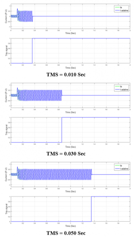
The implementation for simulation of the model of the IDMT overcurrent protective relay based on ADALINE was performed in three steps. For each step, one of the three IDMT characteristic curves was activated. The first step was performed to test the reliability of the model by activating the standard inverse curve. The second was devoted to the very inverse curve and the third test was executed by activating the extremely inverse curve.
For each of the three tests of the implementation for simulation of the proposed model, different values were chosen for the TMS. The chosen values were (0.010 Sec, 0.030 Sec, 0.050 Sec).
For all the simulation steps, a value of (2400 A) was defined as a set-point, this value is equal to a (1.2) multiplied by the nominal current of the power source of the radial power system used for the simulation. This choice is the most adopted in real cases.
In the radial power system used for the simulation, a three-phase ground fault was applied at a time t = 0.1 Sec for all the tests. The results for standard inverse, very inverse and extremely inverse characteristic curves are presented by graphs (Figures 5, 6 and 7) and subsequently discussed.
The results of a single phase are presented (Phase A) as it’s a case of symmetrical fault and the other two phases will be phase shifted by 120 degrees. The current trends are represented using the per unit system by adopting a reference value of 10000 A.
In all the graphs, Ia is the current received by the model of the IDMT overcurrent protective relay based on ADALINE from a TC, I adaline is the fundamental current identified by the ADALINE block.
Infinitesimal errors between Ia and I ADALINE have been recorded, they are due to the choice of an intermediate value for the learning rate (μ = 0.5). The choice of a high value for the learning rate, eliminates totally the errors between Ia and I ADALINE but can generate an instability in the functioning of the proposed model.
Figure 5. Results of the simulation test by activating the SI characteristic curve
Figure 6. Results of the simulation test by activating the VI characteristic curve
The results obtained during the implementation for simulation of the model of the IDMT overcurrent protective relay based on ADALINE have shown its reliability as an overcurrent protective relay. Based on one of the artificial intelligence methods, the model had the ability to identify the fundamental current and detect their overshoot for the set-point.
The Table 1 below summarizes the results of all the tests carried out during the implementation of the model of the IDMT overcurrent protective relay based on ADALINE for simulation via the MATLAB simulating software package.
The model and during all the tests had calculated the operating time necessary for the tripping and it had consequently sent a trip signal to the circuit breaker once the calculated operating time elapsed. It is necessary to confirm the accuracy of the proposed model regarding the calculation of the operating times, the HIL validation section is dedicated to this topic.
Figure 7. Results of the simulation test by activating the EI characteristic curve
Table 1. Results of the implementation for simulation of the model of the IDMT overcurrent protective relay based on ADALINE
|
IDMT characteristic curve |
TMS (Sec) |
overcurrent detection Instant (Sec) |
Calculated operating time by the IDMT block (Sec) |
Tripping instant (Sec) |
|
SI |
0.010 |
0.110 |
0.160 |
0.270 |
|
SI |
0.030 |
0.110 |
0.480 |
0.590 |
|
SI |
0.050 |
0.110 |
0.801 |
0.911 |
|
VI |
0.010 |
0.110 |
0.248 |
0.358 |
|
VI |
0.030 |
0.110 |
0.743 |
0.853 |
|
VI |
0.050 |
0.110 |
1.238 |
1.348 |
|
EI |
0.010 |
0.110 |
0.576 |
0.686 |
|
EI |
0.030 |
0.110 |
1.729 |
1.839 |
|
EI |
0.050 |
0.110 |
2.881 |
2.991 |
The validation of the model of the IDMT overcurrent protective relay based on ADALINE is required. The relay model can be verified by comparing the simulation results to the physical relay testing results [25]. In order to validate the results obtained during the simulation tests, a comparison with a real protective relay has been carried out within SCAMRE laboratory.
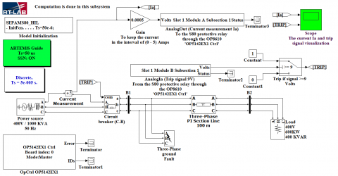
For this purpose, a hardware-in-the-loop (HIL) has been established for an S80 protective relay from Schneider Electric using the OP5600 real-time digital simulator of the OPAL-RT’s technology. A similar model of the radial power system used in the simulation was again used for HIL validation. The radial power system has been developed and adapted to the hardware configuration of the OP5600 using the SimPowerSystems (SPS) toolbox of MATLAB/Simulink as shown in Figure 8.
Figure 8. The radial power system used for the HIL validation
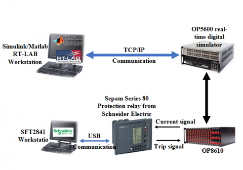
Figure 9 shows the mounting structure used for HIL validation and Figure 10 shows the real mounting used for the HIL validation out within SCAMRE laboratory.
Figure 9. The mounting structure used for HIL validation
The workstation on which the RT-LAB software is installed makes it possible to compile, load and run the radial power system developed on Matlab/Simulink in the OP5600 real-time simulation module.
The OP8610 module was used as an interface between the S80 protective relay and the OP5600 real-time simulation module. It amplifies the current delivered by the OP5600, the send it to the CT connection input on the S80 protective relay. OP8610 receives and transmits to the OP5600 module the trip signal issued by the S80 protective relay in case of the overcurrent fault detection.
Figure 10. The real mounting used for the HIL validation in the SCAMRE laboratory
The workstation on which the SFT2841 software is installed is used to communicate with the S80 protective relay and to parameterize it. This workstation makes it easy to select the overcurrent trip set-point, the TMS values and the desired IDMT characteristic curve.
The S80 protective relay has been submitted to the same tests carried out for the model of the IDMT overcurrent protective relay based on ADALINE during its implementation for simulation. The same set points, TMS values and IDMT curves were chosen for another time in order to obtain results with which the results of the simulation could be compared.
For all tests of the HIL, a three-phase ground fault was applied at a time t = 0.1 Sec in the radial power system developed under Matlab/Simulink and charged in the OP5600 real-time simulation module.
Table 2 below represents a comparison between the tripping instants obtained during the implementation for simulation of the model of the IDMT overcurrent protective relay based on ADALINE and tripping instants obtained during the HIL validation.
Table 2. Comparison between the simulation results and the HIL validation results
|
IDMT curve |
TMS (Sec) |
Simulation tripping instant (Sec) |
HIL validation tripping instant (Sec) |
|
SIT |
0.010 |
0.270 |
0.273 |
|
SIT |
0.030 |
0.590 |
0.592 |
|
SIT |
0.050 |
0.911 |
0.915 |
|
VIT |
0.010 |
0.358 |
0.363 |
|
VIT |
0.030 |
0.853 |
0.857 |
|
VIT |
0.050 |
1.348 |
1.351 |
|
EIT |
0.010 |
0.686 |
0.690 |
|
EIT |
0.030 |
1.839 |
1.844 |
|
EIT |
0.050 |
2.991 |
2.996 |
Errors of very low values (2 to 5 mSec) were recorded between the simulation tripping instants and the HIL validation tripping instants, because the Matlab simulation software package gives ideal results compared to real experiments using the Sepam series 80 protective relay.
lay based on ADALINE has been proposed, developed and tested in simulation via the Matlab simulation software package. The model identifies the fundamental current via one of the artificial intelligence methods; ADALINE is the opted method. The model has also the features of the three IDMT characteristic curves according to the IEC60255 standards: Standard inverse (SI), very inverse (VI) and extremely inverse (EI). In the SCAMRE laboratory and via the OP5600 real-time digital simulator of the OPAL-RT’s technology, the proposed model has been validated by carrying out a hardware-in-the-loop for the S80 protective relay from Schneider Electric. The results of the simulation tests and the HIL validation tests were compared and were eventually almost identical, which confirmed the reliability of the proposed model; its algorithm can be used to develop a valid intelligent IDMT overcurrent protective relay. Several features can be added in future to the IDMT overcurrent protection relay model based on ADALINE namely the faults localization and the faults classification by adding other inputs to the ADALINE block.
[1] Blackburn, J.L., Domin, T.J. (2014). Protective Relaying: Principles and Applications. CRC Press.
[2] Sharaf, H.M., Zeineldin, H.H., Ibrahim, D.K., Essam, E.L. (2015). A proposed coordination strategy for meshed distribution systems with DG considering user-defined characteristics of directional inverse time overcurrent relays. International Journal of Electrical Power & Energy Systems, 65: 49-58. http://dx.doi.org/10.1016/j.ijepes.2014.09.028
[3] Rahmati, A., Dimassi, M.A., Adhami, R., Bumblauskas, D. (2014). An overcurrent protection relay based on local measurements. IEEE Transactions on Industry Applications, 51(3): 2081-2085. http://dx.doi.org/10.1109/TIA.2014.2385933
[4] Abdel-Salam, M., Kamel, R., Sayed, K., Khalaf, M. (2017). Design and implementation of a multifunction DSP-based-numerical relay. Electric Power Systems Research, 143: 32-43. http://dx.doi.org/10.1016/j.epsr.2016.10.033
[5] Abdolkhalig, A., Zivanovic, R. (2015). Simulation and testing of the over-current protection system based on IEC 61850 Process-Buses and dynamic estimator. Sustainable Energy, Grids and Networks, 2: 41-50. http://dx.doi.org/10.1016/j.segan.2015.04.001
[6] Amraee, T. (2012). Coordination of directional overcurrent relays using seeker algorithm. IEEE Transactions on Power Delivery, 27(3): 1415-1422. http://dx.doi.org/10.1109/TPWRD.2012.2190107
[7] Vasilic, S., Kezunovic, M. (2005). Fuzzy ART neural network algorithm for classifying the power system faults. IEEE Transactions on Power Delivery, 20(2): 1306-1314. http://dx.doi.org/10.1109/TPWRD.2004.834676
[8] Yousfi, F.L., Abdeslam, D.O., Bouthiba, T., Nguyen, N.K., Merckle, J. (2012). Adaline for online symmetrical components and phase-angles identification in transmission lines. IEEE Transactions on Power Delivery, 27(3): 1134-1143. http://dx.doi.org/10.1109/TPWRD.2012.2196526
[9] Abdeslam, D.O., Mercklé, J., Wira, P. (2005). Adaline-based estimation of power harmonics. In ESANN, 571-576.
[10] Ukil, A., Deck, B., Shah, V.H. (2010). Current-only directional overcurrent relay. IEEE Sensors Journal, 11(6): 1403-1404. http://dx.doi.org/10.1109/JSEN.2010.2094186
[11] Sung, B.C., Lee, S.H., Park, J.W., Meliopoulos, A.P.S. (2013). Adaptive protection algorithm for overcurrent relay in distribution system with DG. Journal of Electrical Engineering and Technology, 8(5): 1002-1011. http://dx.doi.org/10.5370/JEET.2013.8.5.1002
[12] Soria, O.A., Enríquez, A.C., Guajardo, L.T. (2014). Overcurrent relay with unconventional curves and its application in industrial power systems. Electric Power Systems Research, 110: 113-121. http://dx.doi.org/10.1016/j.epsr.2013.12.012
[13] Hairi, M.H., Aras, M.S.M., Hanaffi, F., Sulaiman, M. (2018). Performance evaluation of overcurrent protection relay based on relay operation time (ROT). International Journal of Electrical Engineering and Applied Sciences (IJEEAS), 1(1): 1-8.
[14] Bakar, A.H.A., Ooi, B., Govindasamy, P., Tan, C., Illias, H.A., Mokhlis, H. (2014). Directional overcurrent and earth-fault protections for a biomass microgrid system in Malaysia. International Journal of Electrical Power & Energy Systems, 55: 581-591. http://dx.doi.org/10.1016/j.ijepes.2013.10.004
[15] Ma, Y., Crossley, P. (2018). Impact of CT saturation on overcurrent relays. The Journal of Engineering, 2018(15): 1274-1280. http://dx.doi.org/10.1049/joe.2018.0188
[16] Noghabi, A.S., Sadeh, J., Mashhadi, H.R. (2009). Considering different network topologies in optimal overcurrent relay coordination using a hybrid GA. IEEE Transactions on Power Delivery, 24(4): 1857-1863. http://dx.doi.org/10.1109/TPWRD.2009.2029057
[17] Jannati, M., Keivanian, R., Eslami, L. (2015). High impedance faults diagnosis in power distribution system based on Adaline harmonic analysis. Science International, 27(1): 87-95.
[18] Chia, K.S. (2015). Predicting the boiling point of diesel fuel using adaptive linear neuron and near infrared spectrum. 2015 10th Asian Control Conference (ASCC), pp. 1-3. http://dx.doi.org/10.1109/ASCC.2015.7244404
[19] Marei, M.I., El-Saadany, E.F., Salama, M.M. (2004). A processing unit for symmetrical components and harmonics estimation based on a new adaptive linear combiner structure. IEEE Transactions on Power Delivery, 19(3): 1245-1252. http://dx.doi.org/10.1109/TPWRD.2004.829110
[20] Sediki, H., Bechouche, A., Abdeslam, D.O., Haddad, S. (2013). ADALINE approach for induction motor mechanical parameters identification. Mathematics and Computers in Simulation, 90: 86-97. https://doi.org/10.1016/j.matcom.2012.05.003
[21] Bechouche, A., Abdeslam, D.O., Seddiki, H., Mesbah, K. (2014). Adaptive ac filter parameters identification of three-phase PWM rectifiers. In IECON 2014-40th Annual Conference of the IEEE Industrial Electronics Society, pp. 1188-1193. https://doi.org/10.1109/IECON.2014.7048653
[22] Yousfi, F.L., Abdeslam, D.O., Nguyen, N.K. (2010). Adaline for fault detection in electrical high voltage transmission line. In IECON 2010-36th Annual Conference on IEEE Industrial Electronics Society, pp. 1963-1968. https://doi.org/10.1109/IECON.2010.5675309
[23] Halbwachs, D., Wira, P., Mercklé, J. (2009). Adaline-based approaches for time-varying frequency estimation in power systems. IFAC Proceedings, 42(19): 31-36. https://doi.org/10.3182/20090921-3-TR-3005.00008
[24] Tung, D.D., Khoa, N.M. (2016). A novel algorithm of directional overcurrent protection relay based on adaptive linear neural network. International Journal of Electronics and Electrical Engineering, 4(6): 494-499. http://dx.doi.org/ 10.18178/ijeee.4.6.494-499
[25] Kezunovic, M., Chen, Q. (1998). A novel approach for interactive protection system simulation. In Proceedings of 1996 Transmission and Distribution Conference and Exposition, pp. 458-464. https://doi.org/10.1109/TDC.1996.547555