Hongyi Xiao * | Rui Li
OPEN ACCESS
The efficiency and time of charging are critical to the application of Farad capacitor. To reduce the loss and enhance the efficiency of Farad capacitor charging, this paper designs a constant power charging system for Farah capacitor based on negative feedback control. Centering on KEAZN64 microprocessor, the system collects the charging voltage and current in real time, which are processed by the microprocessor using the proportional-integral-derivative (PID) algorithm. Then, the microprocessor outputs pulse-width modulation (PWM) signals. Under the control of these signals, the half-bridge drive circuit realizes the constant power charging of Farad capacitor bank. Several experiments were conducted to compare the charging efficiency and time of three charging modes on a Farad capacitor bank, namely, constant voltage charging, constant current charging and constant power charging. The experimental results show that the constant power charging outperformed the other two modes, and the proposed system could charge the Farad capacitor bank with a constant power between 1~60W. The charging efficiency of the system reached 96%. The research findings provide a strong technical support for the promoting of Farad capacitor.
Farah capacitor, proportional–integral–derivative (PID) control, pulse-width modulation (PWM), constant power supply
Farah capacitor is a high energy storage element widely used in power supplies, thanks to its fast charging speed, long cycle life, high current discharge and efficient energy conversion [1-3]. The low impedance of Farah capacitor is indispensable for many high-power applications. Moreover, Farah capacitor can provide short-term power to important storage and memory systems. For small household appliances, a few seconds of charging by Farah capacitor can keep them running for a long time.
Currently, Farah capacitor is generally charged by a direct current (DC) constant voltage supply. This charging method induces a large power loss and consumes a long time [4-5]. To solve the problems, this paper designs a Farah capacitor charging system based on a constant power supply. The system charges Farah capacitor through negative feedback control. Compared with the traditional charging method with constant voltage and constant current, the proposed charging method takes a short time to charge Farah capacitor, achieves a high charging efficiency, and effectively protects the capacitor, extending its service life.
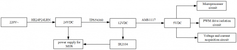
Based on KEAZN64 microprocessor, the system mainly contains the following hardware: half-bridge drive circuit, system power supply circuit, current and voltage sampling circuit, etc. The block diagram of the system is presented in Figure 1 [6-10]. The system power supply provides power to the microprocessor, the sampling circuit, and voltage sensors, and the half-bridge driver. The microprocessor processes the collected data on voltage and current by the proportional-integral-derivative (PID) algorithm, and outputs variable pulse-width modulation (PWM) signals. Under the control of these signals, the half-bridge drive circuit realizes the constant power charging of Farad capacitor bank.
Figure 1. Block diagram of system design
The hardware design of our system focuses on microprocessor circuit, system power supply circuit, PWM drive circuit, half-bridge drive circuit, and current and voltage sampling circuit. Specifically, the microprocessor is of the model S9KEAZN64AMLC produced by the NXP; the PWM drive circuit adopts a 74LVC245 chip for isolation; the half-bridge drive circuit uses an IR2104 driver to drive two N-channel MOS tubes; the current and voltage sampling circuit amplifies signals with an INA270 instrumentation amplifier.
During operation, the analog-to-digital (AD) conversion module of the KEAZN64AMLC microprocessor collects the charging voltage and current of Farah capacitor bank, computes the real-time power, and compares it with the set power. Using the PID algorithm, the microprocessor outputs PWM signals to the 74LVC245 chip. The signals from the chip are transmitted to the IR2104 driver, which then generates two complementary PWM waveforms. The PWM signals control the conduction state of the MOS tubes, thus charging the Farad capacitor bank with a constant power.
3.1 System power supply circuit
The system power supply is powered by 220V mains. The 220V alternating current (AC) is converted by the HE24P24LRN module. The conversion circuit features small size, low ripple and high efficiency. The 24V DC is partially supplied to the MOS tubes, and partially stepped down to 12V DC by a TPS54360 buck converter before being transmitted to the IR2104 driver. The 12V DC is further stepped down to 5V DC by an AMS1117 regulator and then transmitted to the microprocessor, the voltage and current sampling circuit and the PWM drive circuit. The power distribution is specified in Figure 2 below.
Figure 2. System power distribution
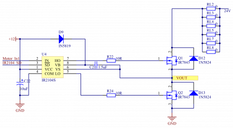
3.2 Half-bridge drive circuit
The half-bridge drive circuit is the main hardware of our system. It was selected to control the system power, aiming to suppress the power loss in the step-down of the input DC voltage. As shown in Figure 3, the two MOS tubes, connected by a totem pole circuit, receive square wave drive signals and output from the midpoint. The IR2104 driver receives the PWM signals and the enable control signals from the microprocessor via pin 2 and pin 3, respectively, and outputs complementary PWM signals with dead time via pins 5 and 7. When pin 7 outputs a high level, the MOS tube Q1 of the upper half-bridge is turned on to charge the Farah capacitor bank; When pin 5 outputs a high level, the MOS tube Q2 of the lower half-bridge is turned on, the resonant circuit (LC) is discharged through Q2, and the microprocessor continuously outputs PWM waves, thus charging the Farah capacitor bank.
Figure 3. Half-bridge drive circuit
3.3 Voltage and current sampling circuit
This circuit collects the voltage and current in the charging process, making it possible to compute the charging power of Farad capacitor [11-14]. The structure of the voltage and current sampling circuit is shown in Figure 4, where P9 is connected to Farad capacitor, and R28 and R30 are two resistors that divide the collected voltage to the range of input voltage required for the AC/DC converter. The charging voltage V of Farad capacitor can be computed by:
$V=A D V \times\left(R_{28}+R_{30}\right) / R_{30}$ (1)
where ADV is the voltage collected by the microprocessor. The voltage across the sampling resistor $R_{27}$ is sampled and amplified by the INA27 instrumentation amplifier. Then, the charging current I of Farad capacitor can be computed by:
$I=A D A /\left(\mathrm{G} * R_{27}\right)$ (2)
where G=14 is the fixed gain of the instrumentation amplifier; ADA is the voltage collected by the microprocessor. On this basis, the charging power P can be derived as:
$P=V \times I$ (3)
Figure 4. Voltage and current sampling circuit
To realize constant power charging, the measured power should be compared with the set power in real time, and the deviation should be substituted into the PID system equations for processing [15]. The new duty cycle outputted by the PID system should be processed and written into the timer, which then outputs a new PWM to control the output power of the half-bridge drive circuit. In this way, the control system forms a closed-loop and completes negative feedback. To ensure the real-time control, the control cycle of the system was set to a small value (about 250μs).
4.1 Feedback control
Based on the voltage and current collected by the sampling circuit, the charging power of Farad capacitor can be obtained by formula (3). Then, the actual charging power is compared with the set power, and the deviation is substituted into the PID algorithm to change the PWM duty cycle. With the new duty cycle, the charging power will be changed to the same level of the set value and remain stable. The feedback control process is shown in Figure 5.
Figure 5. Block diagram of feedback control
4.2 Control flow
In the control algorithm of the KEAZN64-centered system, the microprocessor drives and controls the peripheral circuits to realize the constant power charging of Farad capacitor. The algorithm mainly utilizes the analog-to-digital conversion (ADC) and PWM output functions of the microprocessor. The control flow is explained in Figure 6.
During the control process, the peripheral ADC unit of the microprocessor firstly collects current and voltage data, and then computes the real-time power. Before charging, the target value of charging power is set. Once the charging begins, the deviation and partial differential between the real-time power and the set power are obtained and substituted into the PID equations, outputting the duty cycle increment. The result is then fed back to the timer of the microprocessor, which outputs new PWM waves. Under the control of these waves, the half-bridge drive circuit output a new voltage. Next, the peripheral ADC unit re-collects current and voltage data. In this way, the closed-loop control can be achieved for the constant power charging of Farad capacitor.
Figure 6. Workflow of the control algorithm
Our experiments target a Farad capacitor bank of seven 100F Farad capacitors connected in series. The Farad capacitor bank was subjected to charging tests with constant current, constant voltage and constant power.
5.1 Constant voltage charging
The energy of the Farad capacitor bank was fully released, such that the initial voltage was below 0.1V. Then, the Farad capacitor bank was connected to a DC constant voltage supply. With the set voltage of 10V, the charging current, efficiency and time were measured. Next, the charging curve was plotted as Figure 7.
Figure 7. Constant voltage charging curve
Obviously, there was a huge loss of charging power and continued variation in charging power curve under constant voltage charging, making it difficult to compute the charging data. If the set voltage is too high, the charging power will easily surpass the rated power of the Farad capacitor bank. In this case, the Farad capacitor bank will be damaged and even burned through, sowing the seeds of explosion.
5.2 Constant current charging
The energy of the Farad capacitor bank was fully released, such that the initial voltage was below 0.1V. Then, the Farad capacitor bank was connected to a DC constant current supply. With the set current of 5A, the charging current and efficiency were measured. Next, the charging curve was plotted as Figure 8.
As shown in Figure 8, the charging current remained stable, but the voltage changed continuously, exhibiting an upward trend. Despite this trend, the charging time was lengthened and the initial charging power was low. If the voltage grows to a high level, the charging power will be far greater than the initial power. The power may exceed the storage limit of the Farad capacitor bank, if not properly controlled. In this case, the Farad capacitor bank will be damaged, and a huge loss of power will incur in the charging process.
Figure 8. Constant current charging curve
5.3 Constant power charging
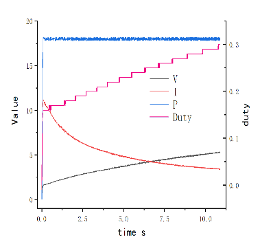
The Farad capacitor bank was connected to our constant power charging system, and charged from 0V to 5V. The charging data, including power, voltage, current and duty cycle, were measured at the set powers of 15W, 18W and 20W, respectively. The relevant waveforms were also plotted. The charging curves of constant power charging are displayed in Figure 9 below.
(1)15W
(2)18W
(3)20W
Figure 9. Constant power charging curves
Comparing the three subfigures of Figure 9, it is learned that the proposed system could reach each set power immediately and remain at the power to charge the Farad capacitor bank. The power curves were smooth and the charging was highly efficient. The constant power charging outperformed the traditional constant voltage charging and constant current charging in terms of charging time and energy conversion rate. In addition, the stability of charging power makes it possible to compute the time to fully charge the Farad capacitor bank, and to implement effective control without damaging the bank.
The experimental results show that our constant power charging system can charge Farad capacitor excellently, laying a solid basis for promoting the application of this type of capacitor.
This paper designs a constant power charging system for Farad capacitor. Centering on KEAZN64 microprocessor, the proposed system contains AD conversion circuit, microprocessor circuit, voltage and current sampling circuit, half-bridge drive circuit, etc. During operation, the charging power is measured in real time, and compared with the set power. Based on the deviation, the microprocessor outputs PWM waves, which drives the half-bridge drive circuit to charge the Farad capacitor bank with a constant power. Experimental results show that the system satisfies the requirements on constant power charging of Farad capacitor, and flexibly adapts to various environments. Compared with the traditional constant voltage charging and constant current charging methods, the proposed constant power charging method boasts a high energy conversion rate, a short charging time, and high charging safety. The proposed system can also be applied independently in various complex supply environments.
[1] Hiraki, E., Yamamoto, K., Tanaka, T., Mishima, T., Nakaoka, M. (2006). An isolated bidirectional DC-DC converter based super-capacitor interface for automobile electric power systems. 2006 12th International Power Electronics and Motion Control Conference. https://doi.org/10.1109/EPEPEMC.2006.4778484
[2] Haubert, T., Mindl, P. (2012). DC/DC power converter for super-capacitor supplied by electric power splitter. Mechanisms and Machine Science, Advances in Mechanisms Design - Proceedings of TMM 2012, 8: 509-515. https://doi.org/10.1007/978-94-007-5125-5_67
[3] Raman, S.R., Xue, X.D., Cheng, K.W.E. (2014). Review of charge equalization schemes for Li-ion battery and super-capacitor energy storage systems. 2014 International Conference on Advances in Electronics, Computers and Communications, ICAECC 2014. https://doi.org/10.1109/ICAECC.2014.7002471.
[4] Li, X., Li, Y., Chang, X. (2016). Nonlinear control algorithm for super capacitor energy storage system based on exact linearization theory. Diangong Jishu Xuebao/Transactions of China Electrotechnical Society, 31(21): 12-20.
[5] Kapali, V., Prasad, O., Parthasarathy, G.M., Sarangapani, K.B., Muralidharan, S., Mania, A. (1998). Comparison of the origin of high capacitance at nickel and/or carbon-aqueous electrolyte interfaces and its uses in the development of potassium ion intercalation based super capacitor. Proceedings of the Annual Battery Conference on Applications and Advances, pp. 411-414. https://doi.org/10.1109/BCAA.1998.653905
[6] Forse, A.C., Merlet, C., Griffin, J.M., Grey, C.P. (2016). New perspectives on the charging mechanisms of supercapacitors. Journal of the American Chemical Society, 138(18): 5731-5744. https://doi.org/10.1021/jacs.6b02115
[7] Hopkins, A., Neville, N.M., Anthony, P., Mellor, P. (2015). High efficiency bidirectional 5kW DC-DC converter with super-junction MOSFETs for electric vehicle super-capacitor systems. 2015 IEEE Energy Conversion Congress and Exposition, ECCE, pp. 4632-4639. https://doi.org/10.1109/ECCE.2015.7310315
[8] Huang, C.W., Huang, T.C., Leu, Y.G. (2013). Stand-alone super capacitor charging system with the design of starting protection. Advanced Materials Research, 740: 403-407. https://doi.org/10.4028/www.scientific.net/AMR.740.403
[9] Jin, L., Wang, W.S., Yu, J.Q., Chen, Z.J. (2018). Design of super capacitor charging management integrated circuit for energy harvesting based on reconfigurable photovoltaic cells array. 2018 IEEE 3rd International Conference on Integrated Circuits and Microsystems, ICICM 2018, pp. 139-143. https://doi.org/10.1109/ICAM.2018.8596597
[10] Jiang, W., Chen, W., Hu, R.J., Wang, X.D., Yang, Y.B. (2014). Charging strategy for super capacitor of photovoltaic generation system. Electric Power Automation Equipment, 34(12): 31-37. https://doi.org/10.3969/j.issn.1006-6047.2014.12.006
[11] Zhang, D.D. (2013). The constant current charging analysis super capacitor. Applied Mechanics and Materials, 274: 312-315. https://doi.org/10.4028/www.scientific.net/AMM.274.312
[12] Katuri, R., Gorantla, S. (2018). Analysis of math function based controller for a smooth transition between battery and ultracapacitor. Mathematical Modelling of Engineering Problems, 5(4): 386-394. https://doi.org/10.18280/mmep.050416
[13] Mukherjee, N. (2015). A state-of-charge equalisation technique of super-capacitor energy storage systems using sub-module DC-DC converter control within modular multilevel converter (MMC) for high speed traction drive applications. 2015 50th International Universities Power Engineering Conference, UPEC. https://doi.org/10.1109/UPEC.2015.7339948
[14] Katuril, R., Gorantla, S. (2018). Comparative analysis of controllers for a smooth switching between battery and ultracapacitor applied to E-vehicle. European Journal of Electrical Engineering, 20(1): 47-75. https://doi.org/10.3166/EJEE.20.47-75
[15] Ben Fathallah, M.A., Ben Othman, A., Besbes, M. (2018). Modeling a photovoltaic energy storage system based on super capacitor, simulation and evaluation of experimental performance. Applied Physics, 124(2): 120. https://doi.org/10.1007/s00339-018-1549-x.