Lei Liu* | Shengtie Wang
OPEN ACCESS
Wind turbine with squirrel-cage induction generators is confronted with major problem for power quality and fail-safe operation at grid fault. State-of-art technique used to meet low voltage ride-through (LVRT) requirements is dynamic reactive power compensation. Meanwhile, breaking resistor and energy storage system is also helpful to LVRT performance. However, these approaches have their own limitations. A hybrid of STATCOM and series dynamic breaking resistor (SDBR) to improve LVRT performance is proposed in this paper. The positive- and negative-sequence independent control is used for STATCOM control to mitigate the voltage fluctuation, while the hysteretic control is adopted for SDBR in order to control bypass switch. A new analytical approach is proposed to quantify the STATCOM rating and SDBR resistance. Simulation results by MATLAB showed that the novel method not only significantly reduces the voltage fluctuations, but also enhances LVRT performance.
low voltage ride-through, series dynamic breaking resistor, STATCOM, squirrel-cage induction generator
Wind energy has become one of the most important green electricity sources due to its free, clean, renewable character and extremely large potential. In recent years, wind power has grown rapidly in the world. With the increasing installed capacity of wind power generation in electrical power system, the grid-connection problem of wind power turns out to be a hotspot to study. Squirrel-cage induction generators (SCIG) are directly connected to the power grid. Normally, due to the effects of turbulence, the wind shear, and the tower shadow and so on, the active and reactive power of SCIG always change, and it will lead to voltage fluctuation and flicker at the point of common coupling (PCC), then the power quality will be reduced. When instantaneous short circuit fault occurs at the PCC, the generator voltage will reduce and the generator speed will improve. So the generator must absorb a lot of reactive power in order to recover to the pre-fault state. All these problems will cause great threats to the safety and stability of power grid, so as to reduce the stability of the power grid.
According to the low voltage ride-through standard by Corporate Standards of State Grid Corporation of China [1], which is shown in Figure 1, the wind turbines should remain connected to the grid when the voltage of the PCC is as low as 20 % of its rated value for 0.625 s. Furthermore, the wind turbines must remain connected as long as the voltage of the PCC reaches 90 % of its rated value within 1.375 sec after the fault has been cleared. However, some operating SCIGs do not have the ability of low voltage ride-through, so state-of-art technique applied to improve LVRT performance becomes the hottest research. STATCOM as a new type of reactive power compensation device is the most widely utilization, due to its low harmonic, quick adjusting speed, wide adjusting range and so on. It can assist in improving the power quality and LVRT ability of the wind farms [2-5], but the device is more expensive. Besides, SDBR which is placed between the wind turbine and the power grid can improve the voltage of PCC under grid fault. It has the advantages of simple control, economical reliable and low failure rate. According to some recent reports [6-9], SDBR can be used for LVRT as well. Although SDBR is regarded as a cost-effective device to enhance the LVRT ability of SCIG, the effect will be reduced when the wind power system is working at low power factor [10]. Meanwhile, certain value of SDBR resistance is difficult to meet all kinds of grid fault. The SDBR resistance which is too large or too small will have an impact on the system [11], thus the design of SDBR resistance is difficult when SDBR is utilized individually.
Figure 1. Low voltage ride-through requirement of wind turbine in China
In this paper, a hybrid of STATCOM and series dynamic breaking resistor to improve LVRT performance of wind turbine is proposed. The method not only overcomes the drawback of SDBR, but also reduces STATCOM rating. Besides, a new analytical approach is proposed to quantify the STATCOM rating and SDBR resistance. It makes the design of SDBR resistance easier. A new control scheme of STATCOM is proposed. STATCOM device adopt the positive- and negative-sequence independent control. While the positive-sequence voltage compensation leads to an increased voltage stability of the wind turbine, the negative-sequence voltage compensation leads to a reduction of system ripple during the unbalance fault. The traditional hysterics control is applied to the bypass switch control of SDBR, in order to reduced oscillation of output voltage. The proposed method is validated by MATLAB with a 900KW SCIG model. It can be seen from comparison in simulation that the system has good LVRT performance by the new method.
2.1 Topology of wind power system
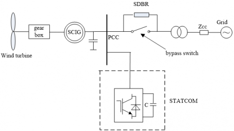
Figure 2 shows the topology of wind power system. It consists of wind turbine with squirrel-cage induction generator, STATCOM, SDBR, bypass switch and power grid. Reactive power compensation devices are usually composed of a capacitor bank of 0.18 Mvar which is connected at the terminal of wind turbine generator and STATCOM based on the voltage source converter principle which is shunt connected at the PCC to provide dynamic reactive compensation and mitigate the voltage fluctuation. The SDBR is connected between the wind turbine and the power grid, and whether it connects into system is controlled by the bypass switch.
Figure 2. Topology of wind power system
2.2 STATCOM rating
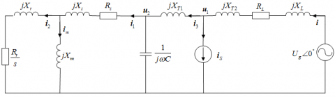
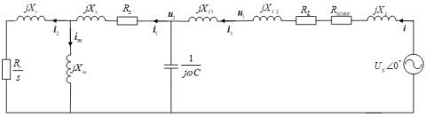
The equivalent circuit of system after a fault is shown in Figure 3, where iSTAT is STATCOM current phasor, Ug is grid voltage phasor, Rg+jXg is grid impedance, jXT2 is equivalent reactance of transformer TR2, jXT1 is equivalent reactance of transformer TR1; 1/jωC represents the capacitor bank. Rs and Rr are the equivalent stator and rotor resistance, Xs, Xr and Xm are the equivalent stator, rotor and magnetizing reactance for identical squirrel cage induction generators. The STATCOM is represented by a constant current source [12].
Figure 3. The equivalent circuit of system after a fault
The relationship between per phase grid voltage and the STATCOM voltage can be expressed by:
${{\dot{U}}_{g}}={{\dot{U}}_{1}}\left[ 1+\frac{{{R}_{L}}+j({{X}_{T2}}+{{X}_{L}})}{{{Z}_{eq2}}+j{{X}_{T2}}}+j\frac{{{R}_{L}}+j({{X}_{T2}}+{{X}_{L}})}{\left| {{{\dot{U}}}_{1}} \right|}\left| {{{\dot{I}}}_{s}} \right| \right]$ (1)
where
${{\dot{I}}_{S}}=j\frac{{{{\dot{U}}}_{1}}}{\left| {{{\dot{U}}}_{1}} \right|}\left| {{{\dot{I}}}_{S}} \right|$,${{Z}_{eq2}}=\frac{{{Z}_{eq1}}}{j\omega c{{Z}_{eq1}}+1}$,${{Z}_{eq1}}=\frac{j{{X}_{m}}(\frac{{{R}_{r}}}{s}+j{{X}_{r}})}{\frac{{{R}_{r}}}{s}+j({{X}_{r}}+{{X}_{m}})}+{{R}_{s}}+j{{X}_{s}}$.
The rotor current can be described as the following formula:
${{\dot{I}}_{2}}=\frac{{{{\dot{U}}}_{1}}}{{{z}_{eq2}}+j{{X}_{T1}}}\times \frac{{{Z}_{eq2}}}{{{Z}_{eq1}}}\times \frac{j{{X}_{m}}}{\frac{{{R}_{r}}}{s}+j({{X}_{r}}+{{X}_{m}})}$ (2)
Then the electromagnetic torque Te is given as:
${{T}_{e}}=\frac{{{R}_{r}}}{12s}\times {{\left| {{{\dot{I}}}_{2}} \right|}^{2}}$ (3)
Assuming zero electromagnetic torque during a fault, from the mechanical equation, the critical clearing time (CCT) can be calculated:
${{t}_{CCT}}\approx 2H\frac{{{n}_{cr}}-{{n}_{in}}}{{{T}_{m}}}$ (4)
where H is the inertia constant, Tm is mechanical torque, nin is initial speed, ncr is critical speed.
(1) Minimum STATCOM Rating Calculation
As shown in the Figure 1, the wind turbines should remain connected to the grid when the voltage at the PCC is as low as 20% of its rated value for 0.625 s. According to the formula (4), the critical speed ncr is given as:
${{n}_{cr}}=\frac{{{T}_{m}}\times {{t}_{CCT}}}{2H}+{{n}_{in}}$ (5)
And the slip s can be shown in the formula below:
$s=\frac{{{n}_{in}}-{{n}_{cr}}}{{{n}_{in}}}$ (6)
If the short fault is cleared, system can maintain stability, rotor speed n must be less than critical speed ncr during a fault. According to the formula (3), the rotor current I2 can be calculated as:
${{I}_{2}}=\sqrt{\frac{{{T}_{e}}}{{{R}_{r}}/s}}$ (7)
The voltage ${{\dot{U}}_{1}}$ is expressed by the rotor current I2 of the asynchronous generator, the formula (1) can be written in this way:
${{\dot{U}}_{g}}=({{r}_{eq,{{I}_{r}}}}+j{{x}_{eq,{{I}_{r}}}}){{\dot{I}}_{r}}+({{r}_{eq,{{I}_{cs}}}}+j{{x}_{eq,{{I}_{cs}}}})\left| {{{\dot{I}}}_{S}} \right|$ (8)
where
$\begin{align} & {{r}_{eq,Ir}}={{R}_{L}}[\frac{{{X}_{r}}}{{{X}_{m}}}+1+\frac{{{R}_{r}}{{R}_{s}}-s{{X}_{s}}\left( {{X}_{r}}+{{X}_{m}} \right)}{s{{X}_{m}}{{X}_{c}}}-\frac{{{X}_{r}}}{{{X}_{c}}}]- \\ & \left( {{X}_{L}}+{{X}_{TR1}} \right)[-\frac{{{R}_{r}}}{s{{X}_{m}}}+\frac{{{R}_{r}}}{s{{X}_{c}}}+\frac{s{{R}_{s}}\left( {{X}_{r}}+{{X}_{m}} \right)+{{R}_{r}}{{X}_{s}}}{s{{X}_{m}}{{X}_{c}}}]+ \\ & \frac{{{R}_{r}}}{s}+\frac{{{R}_{r}}{{X}_{s}}}{s{{X}_{m}}}+{{R}_{s}}\left( \frac{{{X}_{r}}}{{{X}_{m}}}+1 \right)+\frac{{{X}_{TR}}{{R}_{r}}}{s{{X}_{m}}}-\frac{{{X}_{TR}}{{R}_{s}}\left( {{X}_{r}}+{{X}_{m}} \right)}{{{X}_{m}}{{X}_{c}}}-\frac{{{X}_{TR}}{{X}_{s}}{{R}_{r}}}{s{{X}_{m}}{{X}_{c}}} \\\end{align}$
$\begin{align} & {{x}_{eq,Ir}}={{R}_{L}}[-\frac{{{R}_{r}}}{s{{X}_{m}}}+\frac{{{R}_{r}}}{s{{X}_{c}}}+\frac{s{{R}_{s}}\left( {{X}_{r}}+{{X}_{m}} \right)+{{R}_{r}}{{X}_{s}}}{s{{X}_{m}}{{X}_{c}}}]- \\ & \left( {{X}_{L}}+{{X}_{TR1}} \right)[\frac{{{X}_{r}}}{{{X}_{m}}}+1+\frac{{{R}_{r}}{{R}_{s}}-s{{X}_{s}}\left( {{X}_{r}}+{{X}_{m}} \right)}{s{{X}_{m}}{{X}_{c}}}-\frac{{{X}_{r}}}{{{X}_{c}}}]+ \\ & {{X}_{r}}+({{X}_{s}}+{{X}_{TR}})\left( \frac{{{X}_{r}}}{{{X}_{m}}}+1 \right)-\frac{{{R}_{s}}{{R}_{r}}}{s{{X}_{m}}}+\frac{{{X}_{TR}}{{R}_{s}}{{R}_{r}}}{s{{X}_{m}}{{X}_{c}}}-\frac{{{X}_{TR}}{{X}_{s}}\left( {{X}_{r}}+{{X}_{m}} \right)}{{{X}_{m}}{{X}_{c}}} \\\end{align}$
${{r}_{eq,{{I}_{cs}}}}={{R}_{L}}A-({{X}_{L}}+{{X}_{TR1}})B$, ${{x}_{eq,{{I}_{cs}}}}=({{X}_{L}}+{{X}_{TR1}})A+{{R}_{L}}B$
Then req,Ir and xeq,Ir can be calculated.
By the formula (8) can be obtained:
${{\left| {{{\dot{I}}}_{S}} \right|}^{2}}+b\left| {{{\dot{I}}}_{S}} \right|+c=0$ (9)
where
$b=\frac{2\bullet {{I}_{r}}({{r}_{eq,{{I}_{r}}}}\bullet {{r}_{eq,{{I}_{cs}}}}+{{x}_{eq,{{I}_{r}}}}\bullet {{x}_{eq,{{I}_{cs}}}})}{{{r}_{eq,{{I}_{cs}}}}^{2}+{{x}_{eq,{{I}_{cs}}}}^{2}}$
$c=\frac{{{({{r}_{eq,{{I}_{r}}}}\bullet {{I}_{r}})}^{2}}+{{({{x}_{eq,{{I}_{r}}}}\bullet {{I}_{r}})}^{2}}-\left| {{U}_{g}} \right|}{{{r}_{eq,{{I}_{cs}}}}^{2}+{{x}_{eq,{{I}_{cs}}}}^{2}}$ (10)
By solving the above equation, the minimum STATCOM capacity can be obtained, which meet the LVRT requirement.
(2) Maximum STATCOM Rating Calculation
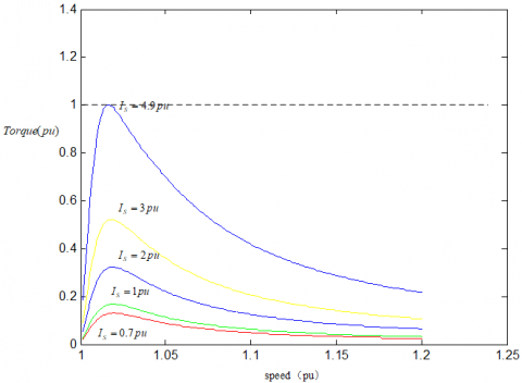
Figure 4. Torque-speed curves for different STATCOM rating during a fault
During a fault STATCOM device injects maximum reactive power into 690 V bus, the voltage of PCC and electromagnetic torque of generator will rise. When the electromagnetic torque of the generator is equal to the mechanical torque, the speed of generator will not rise; the maximum STATCOM capacity can be obtained. According to the formula (1)-(3) a torque-slip curve during a fault, for a given rating of maximum STATCOM current using 0.989 MVA as base values, can be established and is shown in Figure 4.
It can be seen from the Figure 4, the higher the STATCOM current rating, the larger the TCCT and the transient margin. But the maximum electromagnetic torque of SCIG is higher. When the STATCOM current rating is equal to 4.9 pu, the electromagnetic torque of the generator is equal to the mechanical torque.
2.3 STATCOM control strategy
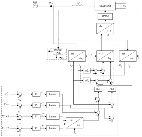
The block diagram of the proposed control strategy is shown in Figure 5, which consists of three building blocks. (1) the positive- and negative-sequence independent control; (2) dual second-order generalized integrators (DSOGI); (3) current decoupled control.
The outer control loops are designed to control the dc voltage and the positive- and negative -sequences of the voltage at the connection point of the STATCOM. Therefore, a precise sequence separation of the measured voltage into positive- and negative-sequence components is necessary, which is performed based on DSOGI [13]. Using the sequence separation, the positive- and the negative-sequence of the voltage appear as dc values and can be controlled by PI controllers. To ensure a safe operation of the STATCOM within its current capability, the current references given by the four outer controllers must be limited to the maximum STATCOM current. The negative-sequence current references must be transformed into the positive rotating reference frame by a coordinate transformation with twice the grid voltage angle. The PI+resonant (PI-R) control for the current inner loop control is presented. Compared with the traditional PI regulator, PI-R control can achieve zero steady-state error to both the fundamental dc reference and the resonant ac reference. Hence the system interference rejection to grid voltage dip is improved, and control accuracy of the proposed scheme is guaranteed.
Figure 5. Block diagram of the proposed complete STATCOM control
STATCOM system is a typical coupling system. While the change of reactive current iq will cause the change of active current id, the change of active current id will also cause the change of reactive current iq.
The decouple controller is as follows:
$\left\{ \begin{align} & {{X}_{1}}(s)=({{K}_{p}}+\frac{{{K}_{i}}}{s}+\frac{2{{\omega }_{c}}{{K}_{R}}s}{{{s}^{2}}+2{{\omega }_{c}}s+{{\omega }_{0}}^{2}})(i_{d}^{*}-{{i}_{d}}) \\ & {{X}_{2}}(s)=({{K}_{p}}+\frac{{{K}_{i}}}{s}+\frac{2{{\omega }_{c}}{{K}_{R}}s}{{{s}^{2}}+2{{\omega }_{c}}s+{{\omega }_{0}}^{2}})(i_{q}^{*}-{{i}_{q}}) \\\end{align} \right.$ (11)
The above formula can be shown that the complete decouple between active current and reactive current is implemented.
In order to ensure the grid side converter and static reactive compensator in wind power systems run safely and reliably under unbalanced grid voltage, it is the basic requirement that the phase and frequency of the positive-sequence fundamental component of grid voltage are obtained quickly and accurately. The dual second-order generalized integrator is presented. The DSOGI not only locks the phase of the positive fundamental component of the PCC voltage, but also detects the positive and negative fundamental component of the PCC voltage. The basic block diagram of the DSOGI-PLL is shown in Figure 6, which consists of four building blocks. (1) quadrature-signals generator (SOGI); (2) positive-sequence calculator module; (3) phase locked loop (PLL); (4) negative-sequence calculator module.
Figure 6. The block diagram of the DSOGI-PLL
The simulation is made to demonstrate that the algorithm is effective and feasible.
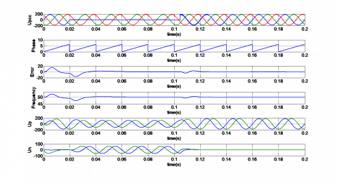
(1) A-phase short circuit fault is considered to occur at 0.02 sec, and the fault is cleared after 1.025 sec. Figure 7 shows responses of the PCC voltage, phase, error, frequency, positive-sequence voltage and negative -sequence voltage.
Figure 7. Simulation waveforms during A-phase short circuit fault
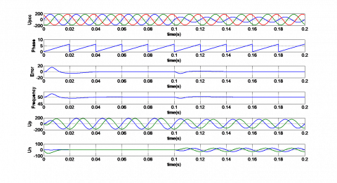
(2) The amplitude of A-phase voltage drops to 50% at 0.1 sec. Figure 8 shows responses of the PCC voltage, phase, error, frequency, positive-sequence voltage and negative -sequence voltage.
Figure 8. Simulation waveforms during voltage unbalance
The Figure 7 and Figure 8 show that, under the condition of voltage unbalance and single -phase short circuit fault, the DSOGI-PLL not only locks the phase of the positive fundamental component of the PCC voltage quickly, but also detects the positive and negative fundamental component of the PCC voltage accurately, and the steady-state error is zero.
3.1 Mechanism analysis
The equivalent circuit of system after a fault is shown in Figure 9.
Figure 9. The equivalent circuit of system (only SDBR)
According to the Figure 9, per phase grid voltage can be expressed by:
${{\dot{U}}_{g}}={{\dot{U}}_{1}}\left[ 1+\frac{{{R}_{L}}+{{R}_{SDBR}}+j({{X}_{T2}}+{{X}_{L}})}{{{Z}_{eq2}}+j{{X}_{T1}}} \right]$ (12)
where ${{Z}_{eq2}}=\frac{{{Z}_{eq1}}}{j\omega c{{Z}_{eq1}}+1}$.
The formula of rotor current and electromagnetic torque is equal to the formula (2) and the formula (3) respectively. According to the formula (2), (3) and (12) a torque-slip curve during a fault, can be established and is shown in Figure 10. As shown in Figure 10, during a fault the higher the SDBR rating, the larger the electromagnetic torque. But the speed of SCIG will rise more slowly. So power system will recover to pre-fault state quickly. When the SDBR rating is equal to 1.5pu, the electromagnetic torque of the generator is equal to the mechanical torque; the speed of SCIG does not continue to rise. Besides, the higher the SDBR rating, the larger the active power consumed by it, and makes the power system oscillation. Under the premise of ensuring the stability of the system, the smaller SDBR resistance is usually chosen.
Figure 10. Torque-speed curves for different SDBR rating during a fault
3.2 SDBR resistance calculation
The analysis is performed neglecting flux transitions of the induction machine [11].
The electromagnetic torque of the generator can be shown in the formula:
${{T}_{\text{e}}}=\frac{3p{{U}^{2}}{{R}_{r}}/s}{{{\omega }_{1}}[({{R}_{s}}+{{R}_{r}}/s)+({{X}_{s}}+{{X}_{r}})]}$ (13)
where p is pole pair, U is terminal voltage, ${{\omega }_{1}}$ is angular velocity.
With $\frac{d{{T}_{\text{e}}}}{ds}=0$, the maximum electromagnetic torque can be given as:
${{T}_{emax}}=\frac{3p{{U}^{2}}}{2{{\omega }_{1}}{{[\sqrt{{{R}_{s}}^{2}+({{X}_{s}}+{{X}_{r}}})}^{2}}+{{R}_{s}}]}$ (14)
And the slip can be expressed by:
${{S}_{emax}}=-\frac{{{R}_{r}}}{\sqrt{{{R}_{s}}^{2}+{{\omega }_{1}}^{2}{{({{X}_{s}}+{{X}_{r}})}^{2}}}}$ (15)
It is pretty obvious that if Temax is always higher than mechanical torque of generator during the fault, the wind turbine will stay stable. Since Semax≈0, mechanical torque Tm can be given as:
${{T}_{m}}=\frac{P}{{{\Omega }_{1}}}=\frac{P}{{{\omega }_{1}}/p}=\frac{Pp}{{{\omega }_{1}}}$ (16)
In order to balance Tm and Temax, we make Tm=Temax. The minimum terminal voltage Umin which makes the wind turbine stable can be calculated as:
${{U}_{\min }}=\sqrt{2Pa/3}$ (17)
where $\sqrt{({{R}_{s}}^{2}+{{({{X}_{s}}+{{X}_{r}})}^{2}}}+{{R}_{s}}]=a$.
(1) Minimum SDBR Rating Calculation
When the most serious short-circuit fault occurs, wind turbine is required to keep connected to the grid. So terminal voltage should be greater than Umin, so as to keep the system stable. We can get the below formula as:
${{U}_{fault}}+P\sqrt{{{({{R}_{SDBR}}+{{R}_{L}})}^{2}}+{{({{X}_{TR}}+{{X}_{TR1}}+{{X}_{L}})}^{2}}}/3{{U}_{\min }}\ge k{{U}_{\min }}$ (18)
where Ufault is the grid voltage during most serious fault which the wind turbine has to connected to the grid required by grid code, k is a safe coefficient which proves the stability margin of the system.
k is always a little bit larger than one so that the calculated terminal voltage will be a little greater than Umin. By the formula (18) can be obtained:
${{R}_{SDBR}}\ge \sqrt{{{[\frac{3{{U}_{\min }}}{{{\operatorname{P}}_{rate}}}(k{{U}_{\min }}-{{U}_{fault}})]}^{2}}-{{({{X}_{TR}}+{{X}_{TR1}}+{{X}_{L}})}^{2}}}-{{R}_{L}}$ (19)
(2) Maximum SDBR Rating Calculation
During a fault SDBR connects into the power system, terminal voltage should not be higher than the rated value, which means that terminal voltage should not be over-improved by SDBR. Here k is still a little bit larger than one because we need additional safe margin to make up the delay of bypass switch.
We can obtain the below formula as:
$k{{U}_{\min }}+P\sqrt{{{({{R}_{SDBR}}+{{R}_{L}})}^{2}}+{{({{X}_{TR}}+{{X}_{TR1}}+{{X}_{L}})}^{2}}}/3{{U}_{rate}}\le {{U}_{rate}}$ (20)
where Urate is the rated terminal voltage.
According to the above formula, we can get:
${{R}_{SDBR}}\le \sqrt{{{[({{U}_{rate}}-k{{U}_{\min }})3{{U}_{rate}}/P]}^{2}}-{{({{X}_{TR}}+{{X}_{TR1}}+{{X}_{L}})}^{2}}}-{{R}_{L}}$ (21)
Combining formula (19) and (21) we can get the range of SDBR rating. To reduce the power loss during the fault, RSDBR should be as low as possible.
3.3 SDBR control strategy
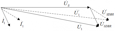
Control structure of SDBR is shown in Figure 11, which adopt the hysteretic control. Upper limits and lower limits of hysteresis comparator are expressed by VrefH and VrefL respectively. Under normal conditions, the bypass switch of SDBR is closed, and the SDBR is not connected to the power grid. When voltage of PCC is lower than the lower limits VrefL, the hysteresis controller sends out the control signal and the bypass switch is opened. Current then flows through the inserted breaking resistor for the period of the fault and the initial post-fault-recovery. When voltage of PCC recovers above upper limits VrefH, the bypass switch is closed and the system restores to its pre-fault state. After SDBR connects into the system, terminal voltage increases because of the voltage drop on the breaking resistor, as shown in Figure 11. Figure 12 also shows that when system has a low power factor, SDBR has little effect on improving voltage of PCC. Since SDBR cannot provide reactive power to the system.
Figure 11. Control structure of SDBR
Figure 12. Phasor diagram of SDBR during the fault
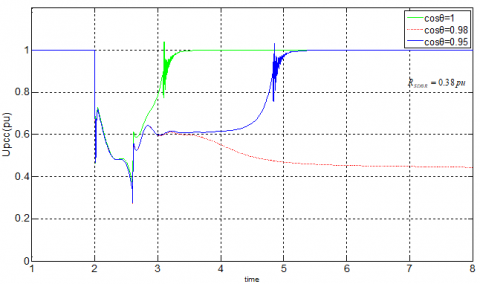
Control effect of SDBR under different power factors is shown in Figure 13. With the decrease of the power factor, the function of SDBR is limited. When the power factor is equal to 0.95, the SDBR has no effect on recovering the voltage of the PCC.
Figure 13. Control effect of SDBR under different power factors
The system configuration is shown in Figure 14, which is used in this study. It consists of wind turbine with squirrel-cage induction generator, STATCOM, SDBR and power grid. Considered wind turbine and STATCOM parameters are shown in Table 1.
Table 1. Wind turbine and STATCOM/HESS parameters
|
Wind turbine |
SN=0.989MVA, PN=0.9MW, RS=0.006pu, XS=0.1413pu, Rr=0.0066pu, Xr=0.0463pu, Xm=4.1338pu, UN=690V, f=50/60Hz, Jg=5.8078, fc=0.01, p=2. |
|
STATCOM |
QSTATCOM=600kvar, Lf=0.495mH, Cdc=0.0213F, Cf=0.121mF, Udc=1500V. |
Figure 14. The system configuration
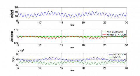
4.1 Mitigation of voltage fluctuation caused by interference wind
The interference wind with mean speed of 12 m/s is applied to the system, in order to study the influence of the interference wind on the voltage fluctuation. Simulation curves are shown in Figure 15, including the wind speed, the PCC voltages with and without STATCOM, and the reactive powers generated by STATCOM and wind turbine. We can see clearly in the figure that the PCC voltage fluctuates in the range of -3%~0.2% without STATCOM for reactive power compensation. Contrarily, the PCC voltage varies in the range of -0.2%~0.2% with STATCOM. The conclusion is that the STATCOM reduces the voltage fluctuations which caused by the interference wind and improves the power quality of wind turbine.
Figure 15. The simulation curve under interference wind
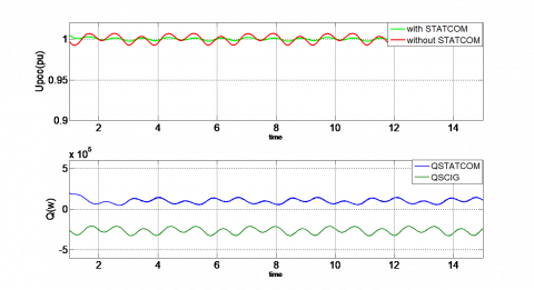
4.2 Mitigation of voltage fluctuation caused by gradient and tower Shadow
An expression for the aerodynamic torque applied to the wind turbine that also includes the gradient and the tower shadow effects is given below where A=0.1 and B=0.2 [14].
$T={{T}_{0}}[1+A\sin ({{\omega }_{WT}}t)+B\sin (3{{\omega }_{WT}}t)]$ (22)
where, T0 is the average torque, ωWT is the rotational speed of wind turbine rotor.
Figure 16. The simulation curve under the gradient and tower shadow effect
The PCC voltage curves with and without STATCOM are compared in Figure 16. It is apparent from the chart that STATCOM reduces the voltage fluctuations and regulates the PCC voltage in an acceptable range by injecting the reactive power at PCC.
4.3 Voltage stabilization during a three phase short fault
Wind speed of 12 m/s is applied to the system. A three-phase short circuit fault is occurred in the 110 KV bus at 2.0 sec, and the fault is cleared after 0.6 sec. The voltage drops to 20%.
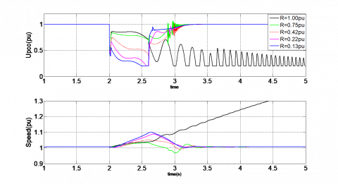
(1) With SDBR and without STATCOM
Simulation curves are shown in Figure 17, including the PCC voltage, rotor speed of the SCIG. During the Short fault, the electromagnetic torque is close to zero, and the torque coming from wind turbine make the rotor speed linearly increased. Since SDBR connected into the system, the voltage of PCC was raised and the rotor speed was raised slowly. When the short fault is cleared, voltage of PCC is still not reach to the upper limits VrefH. SDBR is not removed from the power grid. The PCC voltages and the rotor speed recover to their pre-fault nominal values quickly, and the wind turbine remains connected to the power grid. The higher the SDBR rating, the shorter the recovery time. And the speed of SCIG will rise more slowly. When the resistance of SDBR is equal to 1 pu, the System became oscillating, which means that the resistance is too big to ride through the fault because of extremely low power factor during the fault.
Figure 17. Simulation waveform with different SDBR
(2) With SDBR and STATCOM
Simulation curves are shown in Fig.18, including the PCC voltage, rotor speed of the SCIG and reactive power of the STATCOM. It can be seen from the figure, combination of STATCOM and SDBR remain stable after a fault. With the increase of the resistance of SDBR, the speed of SCIG rises more slowly and the recovery time becomes shorter. Besides, the output reactive power compensation capacity of STATCOM is reduced. It is proved that the proposed system could realize good LVRT performance with lower STATCOM rating, thus lower cost.
Figure 18. Simulation waveform with STATCOM and different SDBR
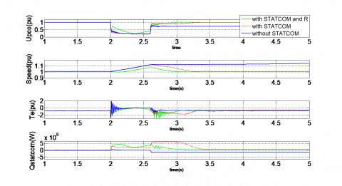
(3) Comparative analysis
Comparison of three schemes is shown in Figure 19, including the PCC voltage, rotor speed of the SCIG, electromagnetic torque and reactive power of the STATCOM. When the short fault is cleared, the generator is not able to produce enough braking torque to bring the speed and the PCC voltage back to their pre-fault values without STATCOM and SDBR. As a result, the wind turbine has to be disconnected from the power grid. On the contrary, with STATCOM for reactive power compensation and SDBR, the PCC voltages and the rotor speed recover to their pre-fault nominal values, and the wind turbine remains connected to the power grid. Besides, the recovery time of combined STATCOM and SDBR is shorter than it of only STATCOM, and the speed of SCIG rises more slowly. So combined STATCOM and SDBR improves transient stability and the low voltage ride-through capability of wind turbine.
Figure 19. Comparison of three schemes
The use of combined STATCOM and SDBR is studied to mitigate the voltage fluctuations and improve fault ride-through capability of a wind turbine in this paper. In order to assure STATCOM to run safely and reliably in both normal and faulty conditions, a novel control strategy which combines the positive- and negative- sequence independent control is proposed to improve the stability of grid voltage, while the hysteretic control is adopted for SDBR in order to control bypass switch. A new analytical approach is proposed to quantify the STATCOM rating and SDBR resistance. Simulation model which contains wind turbine with squirrel-cage induction generator, STATCOM, SDBR and power grid is established in the MATLAB/SIMULINK environment and the simulation results showed that the Combination not only significantly reduces the voltage fluctuations caused by interference wind, gradient and tower Shadow, improves the power quality and enhances fault ride-through capability of wind turbine, but also reduces STATCOM rating.
This work was supported by Science and Technology Research Project for Colleges and Universities in Inner Mongolia Autonomous Region (NJZY19076).
[1] Technical Rule for Connecting Wind Farm into Power Grid, Corporate Standards of State Grid Corporation of China Q/GDW 392-2009, Feb.2010.
[2] Tian, G.Z., Wang, S.T., Liu, G.C., Wang, W.P. (2013). Mechanism analysis and experimental research on improving performance of wind farm with squirrel-cage induction generators by STATCOM. Power System Technology, 37(7): 1971-1977.
[3] Zhang, M., Zhang, J.Y., Lv, M.Y., Tang, D.C., Yi, Z.W. (2014). Reactive power compensation control of STATCOM based on the improved law of variable structure control. Control Engineering of China, 21(1): 5-8.
[4] Wessels, C., Hoffmann, N., Molinas, M., Fuchs, F.W. (2013). STATCOM control at wind farms with fixed-speed induction generators under asymmetrical grid faults. IEEE Transactions on Industrial Electronics, 60(7): 2864-2873. https://doi.org/10.1109/TIE.2012.2233694
[5] George, S.K., Chacko, F.M. (2013). Comparison of different control strategies of STATCOM for power quality improvement of grid connected wind energy system. 2013 International Multi-Conference on Automation, Computing, Communication, Control and Compressed Sensing (iMac4s), 650-655. https://doi.org/10.1109/iMac4s.2013.6526394
[6] Hossain, M.K., Ali, M.H. (2014). Low voltage ride through capability enhancement of grid connected PV system by SDBR. 2014 IEEE PES T&D Conference and Exposition, 1-5. https://doi.org/10.1109/TDC.2014.6863248
[7] Rashid, G., Ali, M.H. (2014). A modified bridge-type fault current limiter for fault ride-through capacity enhancement of fixed speed wind generator. IEEE Transactions on Energy Conversion, 29(2): 527-534. https://doi.org/10.1109/TEC.2014.2304414
[8] Soliman, H., Wang, H., Zhou, D., Blaabjerg, F., Marie, M.I. (2014). Sizing of the series dynamic breaking resistor in a doubly fed induction generator wind turbine. 2014 IEEE Energy Conversion Congress and Exposition (ECCE), 1842-1846. https://doi.org/10.1109/ECCE.2014.6953642
[9] Tang, F., Liu, T.Q., Li, X.Y. (2010). Improving transient stability of wind farm consisting of fixed speed induction generator by series connected dynamic braking resistors. Power System Technology, 34(4): 163-167.
[10] Zhou, Z. (2012). Fixed-speed asynchronous wind turbine model and transient stability. Harbin Institute of Technology, Harbin.
[11] Zhou, L.Y., Liu, J.J., Liu, F.C. (2010). Low voltage ride-through of wind farms using STATCOM combined with series dynamic breaking resistor. The 2nd International Symposium on Power Electronics for Distributed Generation Systems, pp. 841-845. https://doi.org/10.1109/PEDG.2010.5545755
[12] Molinas, M., Jon, A.S., Undeland, T. (2008). Low voltage ride through of wind farms with cage generators: STATCOM versus SVC. IEEE Trans. Power Electronics, 23(3): 1104-1117. https://doi.org/10.1109/TPEL.2008.921169
[13] Kong, F.F., Yuan, T.J., Chao, Q., Li, J.L., Zhu, X. (2012). A method of converter power grid synchronization based on second-order generalized integral. Power System Protection and Control, 40(12): 116-120.
[14] Lopes, L.A., Lhuilier, J., Khokar, M.F., Mukherjee, A. (2005). A wind turbine emulator that represents the dynamics of the wind turbine rotor and drive train. 36th IEEE Power Electronics Specialists Conference, pp. 2092-2097. https://doi.org/10.1109/PESC.2005.1581921
[15] Muyeen, S.M. (2015). A combined approach of using an SDBR and a STATCOM to enhance the stability of a wind farm. IEEE Systems Journal, 9(3): 922-932. https://doi.org/10.1109/JSYST.2013.2297180
[16] Liu, J.H., Zheng, Y.H., Yao, G., Wang, X., Shao, Z.D. (2012). Static synchronous compensator control method based on self-harmonic compensation. Low Voltage Apparatus, 24.