Mustafa Emre Yetkin* | Ferhan Şimşir
© 2020 IIETA. This article is published by IIETA and is licensed under the CC BY 4.0 license (http://creativecommons.org/licenses/by/4.0/).
OPEN ACCESS
Beside many parameters, the stresses occurring on roof and gob zone of a longwall face are mostly depending on face dip angle, thickness of overburden layers and mining height. The rise of stresses, on the other hand, causes often unwanted cavings at face, penetrations of machines and equipment into footwall, and abrupt caving of roof layers at face rear endangering safety of underground mining operations. This study analyzes powered roof supports’ load bearing capacity considering the stress state on roof and gob zones at different face advance angles, and establishes the numerical model of a longwall face.
Here, in order to determine a powered support’s bearing capacity, average stress distributions that occur on roof and gob zones are calculated using numerical models for various face advance angles considering a mining height of 3m and longwall top coal caving (LTCC) as working method. The procedure mentioned above is applied to a running underground coal mine where nine distinct longwall types are modelled considering rock mass properties of surrounding strata and different face advance angles. In conclusion, the most suitable interaction between face advance angles and support bearing capacities for the mine under study are determined.
longwall, coal mining, numerical modelling, support bearing capacity, rock mechanics
Longwall is a mining method widely used in underground coal mines. It is the preferred method of mining a flat-lying stratiform ore body when a high area extraction ratio is required and a pillar mining method is precluded. The method is applicable to both metalliferous mining in a hard-rock environment and coal mining in soft rock [1]
Longwall top coal caving (LTCC) is more productive and cost-effective compared to traditional single pass longwall method. It has been one of the major methods for extracting thick (>5m) to ultra-thick coal seams with complex occurrence conditions around the world in recent years [2-9].
Nowadays, speed of supporting the roof has reached the excavation speed in longwall mining, so, the importance of powered roof support used in the face have increased. Powered roof supports are the most important equipment of fully-mechanized longwall mining in terms of providing a comfortable working environment, allowing rapid driving and production, and supporting transportation units. The panel dip angles (in other words the face advance angles) vary depending on the stratification of the coal seam. At faces where self-advancing support units are used, the stresses on roof of the face and the gob zone are increasing or decreasing with the change in face advance angle. This change of stresses, on the other hand, causes rising or decreasing of a support’s load bearing capacity. Up to now, many field studies and experimental works have been carried out by various researchers and as a result of these studies, a number of different methods and theories have been developed regarding the determination of a support’s load bearing capacity [10-16].
The stress state on roof and gob of a longwall panel operating at a certain face advance angle can be predicted using numerical modelling software. Determination of a powered support’s maximum load bearing capacity considering stresses which are to occur on roof and gob of a face is of advantage for mining companies and engineers. In recent years, the calculation of load bearing capacity of a self-advancing support by using numerical modelling techniques has increasingly become an important issue among researchers [4, 8, 16-27].
In this study, face height is taken as 3m representing the real colliery working parameter, whereas the face advance angles are modelled as 0°, 5°, 10°, 15°, 20°, both rising and dipping, and so, 9 distinct face models are developed. Average stresses on roof and gob zones of these longwall faces which were modelled considering mechanical properties of coal seam and surrounding rocks and face advance angles, are then calculated. According to these stresses and considering the dimensions of the roof canopy of the support unit being used in the colliery, maximum load bearing capacity of a support unit is computed and the range of supports’ maximum load bearing capacity at various face advance angles is then determined.
2.1 Geology
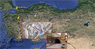
The state-run Omerler colliery, a subsidiary of Turkish Coal Enterprises, is situated in Western Turkey near the province Kutahya (Figure 1). The total proven lignite reserve in the district is about 330 Mt of which 263 Mt can only be mined out in underground and the rest 67 Mt is suitable for surface production. Coal production at Omerler colliery has started in 1985 at an average depth of approx. 240 m. The thickness of the coal seam is around 8 m with an average dip of 10° [20, 28-31].
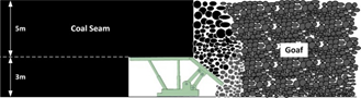
Here, coal is mined out by means of retreating longwalls with top coal caving in 3m high longwall faces set up at bottom of the coal seam. The remaining 5m thick top slice of the seam is being caved and produced through folding gob shield located at the rear of the shields (Figure 2).
Figure 1. Location map of study field
Figure 2. Longwall top coal caving method applied in the study area
2.2 Properties of coal measure rocks
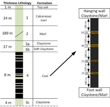
A generalized lithologic column showing the coal seam together with roof and floor strata is given in Figure 3. There are three main geological layers in the mine area which are claystone, clayey marl and marl. There is a 30-80 cm thick soft claystone layer (3b) at the roof contact of the coal seam which frequently creates roof instability problems because of its low strength. There is another claystone layer (3a) just above the soft claystone layer which is stronger than the soft claystone. There is also another claystone layer (3c) having more sturdy features and an average thickness of 4 m, forming the footwall of the longwall face. The coal seam itself contains three clay bands having thicknesses of 15, 75 and 55cm (from top to bottom), respectively [20, 28-31].
Figure 3. A generalized and coal seam stratigraphic column at Omerler colliery [29]
2.3 Rock mass and rock material properties
One of the most important steps in numerical modelling is the assessment of input parameters. Rock material properties should be evaluated carefully in order to find satisfactory results in modelling with Phase2D [32]. That’s why, physical and mechanical properties of each stratum should be studied in detail. Generally, first laboratory experiments are carried out to find intact rock properties such as uniaxial compressive strength, tensile strength and geological strength index at first. However, there are important differences between rock material and rock mass properties. Therefore, it is important to use rock mass properties instead of rock material properties in numerical modelling. Laboratory studies have been carried out on core samples taken from the JT-4 borehole, which was drilled to investigate the geomechanical features of the surrounding rocks of the coal seam in the working area. The results of these studies are given in Table 1 [20, 29-31].
By using rock material’s mechanical properties obtained by laboratory tests, mechanical parameters of the rock mass are then found out with the help of the software RocData [33]. This software is used to convert geomechanical parameters obtained from rock material during field modelling studies into rock mass parameters using several failure criteria, since the formations during field modelling works are to be represented as rock mass and not as rock material. Rock mass properties of these zones are given in Table 2.
Table 1. Physical and mechanical properties of intact coal and surrounding rocks
|
Properties |
Calcareous marl |
Marl |
Claystone |
Coal |
||
|
(3a) |
(3b) |
(3c) |
|
|||
|
Unit weight (g) (MN/m3) |
0.023 |
0.022 |
0.021 |
0.023 |
0.024 |
0.013 |
|
Uniaxial compressive strength (sc) (MPa) |
29.20 |
16.10 |
12.00 |
11.52 |
24.50 |
12.15 |
|
Young’s modulus (Ei) (MPa) |
5520 |
2530 |
2785 |
1669 |
3204 |
1748 |
|
Geological strength index (GSI) |
52 |
52 |
52 |
52 |
52 |
47 |
Table 2. Rock mass properties of coal and surrounding rocks used in models
|
Formation |
Unit weight (MN/m3) |
Young’s modulus (MPa) |
Poisson’s ratio (n) |
Tensile strength (MPa) |
Internal friction angle (°) (f) |
Internal friction angle (°) (f) (Residual) |
Cohesion (c) (MPa) |
Cohesion (c) (MPa) (Residual) |
|
Coal |
0.0130 |
519.64 |
0.25 |
0.046891 |
27.8798 |
- |
0.238185 |
- |
|
Zone of relaxation |
0.0130 |
70 |
0.28 |
0.006380 |
18.5989 |
- |
0.115901 |
- |
|
Gob |
0.0140 |
100 |
0.40 |
0 |
28 |
25 |
0.11 |
0.10 |
|
Coal behind face |
0.0140 |
50 |
0.40 |
0 |
28 |
25 |
0.11 |
0.10 |
3.1 Structural model of longwall strata
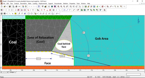
The determination of geomechanical properties of rock mass is the most important stage of modelling works. By considering these parameters, the longwall face is divided into 4 sections as coal seam, relaxation zone, coal behind face, and gob zone. The face itself is modelled in accordance with dimensions of the shield support used in the colliery (Figure 4). The lengths of the roof canopy and caving shield of the support unit are 4.5m and 4m, respectively.
The input data given in Table 2 are then assigned to the sections defined at the model and so the model is completed. The stresses directly upon the longwall opening are mainly affected by the relaxation zone and the coal area behind the face. During longwall mining, the area directly upon the longwall opening undergoes a deformation and tends to cave towards the face rear as a result of coal production and face advance. Therefore, the rock mass in this area has weaker mechanical properties than the rock mass in the immediate roof. This area is called the relaxation zone (Figure 4). According to the evaluations and investigations made earlier, it has been stated that the technical parameters such as elasticity modulus, Poisson’s ratio, internal friction coefficient, cohesion and tensile strength of the coal broken from roof and caved into face rear have to be smaller than that of the coal to be found in the relaxation zone (upon the face) [34]. For this reason, when modelling the coal area behind the face, it is assumed that the coal broken and caved into face rear will behave like cavings and so geotechnical parameters of the gob area are then taken into consideration (Table 2).
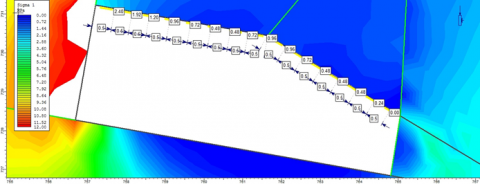
3.2 Longwall modeling
The nine distinct longwalls mentioned before have been modelled using the modelling software Phase2D [32]. By running these models, the mean stresses on the relaxation zone lying directly upon the face opening and on the sections where caved material is in contact with the canopy and the caving shield of the support unit are computed. To achieve a more accurate and exact evaluation when calculating the stresses, the stress values in these areas are read at 50cm intervals and the mean of these readings are then taken (Figure 5).
Figure 4. Numerical model of the rock mass around longwall face
Figure 5. The stresses occurring around the face having a height of 3m and rising at 10°
Figure 6. Liner support to represent powered roof support
Table 3. Input data used for liner support at the model
|
Young's Modulus (MPa) |
Poisson Ratio |
Unit Weight (MN/m³) |
|
209670 |
0.3 |
0.0785 |
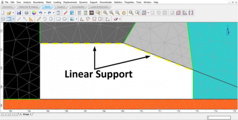
3.3 Representing powered roof support in model
Powered roof supports used in longwall faces bear and transmit the loads and stresses coming from roof and caved zone to footwall. For this reason, to represent the powered roof support in the model and to constitute a structure showing resistance to loads coming from roof, liner support application has been carried out. The parts of the powered roof support contacting to roof and gob zone are canopy and caving shield, respectively. These parts of the support unit used in the colliery are made of Q460 steel, so, mechanical properties of this steel type that are given in Table 3 have been entered into model for the liner support to ensure this support to act as the powered roof support. The liner support in the model is shown in Figure 6.
Table 4. Support densities at setting and yield loads
|
Load type |
in kN |
in t |
Canopy dimensions |
Support density (MPa) |
||
|
Length (m) |
Width (m) |
Area (m2) |
|
|||
|
Setting load |
6280 |
640.10 |
4.5 |
1.75 |
7.875 |
0.81 |
|
Yield load |
7264 |
740.40 |
0.94 |
|||
3.4 Properties of powered roof support
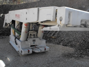
The in-face shield support unit used at Omerler colliery is shown in Figure 7. When looking at the technical properties of the support unit, it can be seen that the support density at setting load is about 0.81 MPa and that at yield load is about 0.94 MPa. Considering the surface area of the roof canopy, support unit’s load bearing capacity is 640.10 t at setting and 740.40 t at yield (Table 4).
Figure 7. View of in-face support unit
The average stresses occurring on roof and gob zones of the face at different face advance angles are given in Table 5.
Table 5. Average stress distribution on different face advance angles
|
Face advance angle (°) |
Support working height (m) |
Average stress (MPa) |
|
|
Roof zone |
Gob zone |
||
|
-20 |
3 |
0.77 |
0.15 |
|
-15 |
1.01 |
0.00 |
|
|
-10 |
0.78 |
0.05 |
|
|
-5 |
0.92 |
0.14 |
|
|
0 |
0.31 |
0.00 |
|
|
5 |
0.90 |
0.10 |
|
|
10 |
0.42 |
0.00 |
|
|
15 |
0.71 |
0.23 |
|
|
20 |
0.70 |
0.26 |
|
For an efficient supporting, the roof canopy of the designed support unit has to be in full contact with the roof layers. Thus, the pressure affecting the support unit vertically determines the load bearing capacity of the support at the same time. The mean stress values occurring at roof area given in Table 5 are multiplied by the surface area of the support unit’s roof canopy and so load bearing capacity of the support unit has been calculated for different face advance angles. The results are given in Table 6 and Figure 8.
According to the data given in Table 5, it can be seen that the stresses occurring on roof and gob at 3 m face height generally increase when working rising or underhand compared to horizontal working (face advance angle is then 0°). Because of the rise in stresses, load bearing capacities of support units to be used at these face advance angles should also be higher. Considering the maximum load bearing capacity of the support unit still used at the colliery (740.40 t), it can be seen that this capacity is reached at working underhand at face advance angles of 6°, 13° and 17° and excesses this value at 15° (Figure 8). The maximum load bearing capacity of the support unit to be used between these angles has to be chosen at least as 795.38 t.
Table 6. Load bearing capacities of the support unit at different face advance angles and stresses
|
Face advance angle (°) |
Average stress at roof zone |
Canopy area (m2) |
Max. support bearing capacity (t) |
|
|
MPa |
t/m2 |
|
|
|
|
-20 |
0.77 |
77 |
7.875 |
606.38 |
|
-15 |
1.01 |
101 |
795.38 |
|
|
-10 |
0.78 |
78 |
614.25 |
|
|
-5 |
0.92 |
92 |
724.50 |
|
|
0 |
0.31 |
31 |
244.13 |
|
|
5 |
0.90 |
90 |
708.75 |
|
|
10 |
0.42 |
42 |
330.75 |
|
|
15 |
0.71 |
71 |
559.13 |
|
|
20 |
0.70 |
70 |
551.25 |
|
Figure 8. Load bearing capacities of the powered support unit at different face advance angles
At setting up a longwall face, the cost of support units comprises a large part of total investment costs, therefore, proper selection of supports suitable to working conditions is of great importance. Here, the most determining feature is the maximum load bearing capacity of the support unit. According to results obtained by a well-done modelling considering field data, maximum load bearing capacities of support units can be determined.
In this study, mean stresses on roof and gob areas at longwall models set up using field data are determined at various face advance angles. The maximum load bearing capacity of the support unit used at the operating colliery is calculated considering the surface area of the roof canopy, also. It is foreseen that in view of load bearing capacity no problems will occur at the colliery when working rising up to an angle of 20°. On the other hand, when working underhand at angles between 6° and 13°-17°, the maximum load bearing capacity of the support unit should at least be 795.38 t.
[1] Peng, S.S., Chiang, H.S. (1984). Longwall Mining. New York: Wiley.
[2] Unver, B., Yasitli, N.E. (2006). Modelling of strata movement with a special reference to caving mechanism in thick seam coal mining. International Journal of Coal Geology, 66(4): 227-252. https://doi.org/10.1016/j.coal.2005.05.008
[3] Wang, J.C. (2009). The Theory and Technique on the thick Coal Seam Mining. Beijing: Metallurgical Industry Press, 48-50.
[4] Alehossein, H., Poulsen, B.A. (2010). Stress analysis of longwall top coal caving. International Journal of Rock Mechanics and Mining Sciences, 47(1): 30-41. https://doi.org/10.1016/j.ijrmms.2009.07.004
[5] Vakili, A., Hebblewhite, B.K. (2010). A new cavability assessment criterion for Longwall Top Coal Caving. International Journal of Rock Mechanics and Mining Sciences, 47(8): 1317-1329. https://doi.org/10.1016/j.ijrmms.2010.08.010
[6] Ghosh, A.K., Gong, Y. (2014). Improving coal recovery from longwall top coal caving. Journal of Mines, Metals and Fuels, 62(3): 51-57, 64.
[7] Khanal, M., Adhikary, D., Balusu, R. (2014). Prefeasibility study—Geotechnical studies for introducing longwall top coal caving in Indian mines. Journal of Mining Science, 50: 719-732. https://doi.org/10.1134/s1062739114040139
[8] Wang, J. (2014). Development and prospect on fully mechanized mining in Chinese coal mines. International Journal of Coal Science and Technology, 1: 253-260. https://doi.org/10.1007/s40789-014-0017-2
[9] Basarir, H., Ferid Oge, I., Aydin, O. (2015). Prediction of the stresses around main and tail gates during top coal caving by 3D numerical analysis. International Journal of Rock Mechanics and Mining Sciences, 76: 88-97. https://doi.org/10.1016/j.ijrmms.2015.03.001
[10] Wilson, A.H. (1975). Support load requirements on longwall faces. Min Eng., 134: 479-491.
[11] Smart, B.G.D., Redfern, A. (1986). The evaluation of powered support from geological and mining practice specifications information. Proceedings of the 27th U.S. Symposium on Rock Mechanics (USRMS), Tuscaloosa, Alabama.
[12] Barczak, T.M., Oyler, D.C. (1991). A model of shield-strata interaction and its implications for active shield setting requirements. Report of Investigations 9394. United States Department of the Interior.
[13] Özel, R, Ünal, E. (1998). Support and strata interaction in longwall faces. International Journal of Rock Mechanics and Mining Sciences, 35(4-5): 484-485. https://doi.org/10.1016/S0148-9062(98)00065-5
[14] Langosch, U., Ruppel, U., Wyink, U. (2003). Longwall roof control by calculation of the shield support requirements. In: Proceedings of the Coal Operators’ Conference, pp. 162-172.
[15] Peng, S.S. (2006). Longwall Mining, 2nd Edition. Morgantown.
[16] Hosseini, N., Goshtasbi, K., Oraee-Mirzamani, B., Gholinejad, M. (2014). Calculation of periodic roof weighting interval in longwall mining using finite element method. Arabian Journal of Geosciences, 7: 1951-1956. https://doi.org/10.1007/s12517-013-0859-8
[17] Xie, H., Chen, Z., Wang, J. (1999). Three-dimensional numerical analysis of deformation and failure during top coal caving. International Journal of Rock Mechanics and Mining Sciences, 36(5): 651-658. https://doi.org/10.1016/S0148-9062(99)00027-3
[18] Yavuz, H. (2004). An estimation method for cover pressure re-establishment distance and pressure distribution in the goaf of longwall coal mines. International Journal of Rock Mechanics and Mining Sciences, 41(2): 193-205. https://doi.org/10.1016/S1365-1609(03)00082-0
[19] Prusek, S., Rajwa, S., Walentek, A. (2005). An application of numerical modeling for the assessment of the roof stability between the coal face and the tip of canopy. Proceedings of the XII International Scientific Conference, Górnicze Zagro \.zenia Naturalne. Katowice, pp. 229–252 (In Polish).
[20] Yasitli, N.E., Unver, B. (2005). 3D numerical modeling of longwall mining with top-coal caving. International Journal of Rock Mechanics and Mining Sciences, 42(2): 219-235. https://doi.org/10.1016/j.ijrmms.2004.08.007
[21] Saeedi, G., Shahriar, K., Rezai, B., Karpuz, C. (2010). Numerical modelling of out-of-seam dilution in longwall retreat mining. International Journal of Rock Mechanics and Mining Sciences, 47(4): 533-543. https://doi.org/10.1016/j.ijrmms.2009.11.005
[22] Xie, G.X., Chang, J.C., Yang, K. (2009). Investigations into stress shell characteristics of surrounding rock in fully mechanized top-coal caving face. International Journal of Rock Mechanics and Mining Sciences, 46(1): 172-181. https://doi.org/10.1016/j.ijrmms.2008.09.006
[23] Singh, G.S.P., Singh, U.K. (2009). Assessment of dynamic loading and rapid yield valve requirement for powered roof supports in longwall workings. Mining Technology, 118(1): 47-52. https://doi.org/10.1179/037178409x12450752943207
[24] Islam, M.R., Hayashi, D., Kamruzzaman, A.B.M. (2009). Finite element modeling of stress distributions and problems for multi-slice longwall mining in Bangladesh, with special reference to the Barapukuria coal mine. International Journal of Coal Geology, 78(2): 91-109. https://doi.org/10.1016/j.coal.2008.10.006
[25] Huang, Z.Z., Ren, Y.F., Zhang, H.J. (2010). Study on key technology of fully mechanized top coal caving in extra-thick soft coal seam with great dip angle. Journal of China Coal Society, 35(11): 1878-1882.
[26] Likar, J., Medved, M., Lenart, M., Mayer, J., Malenković, V., Jeromel, G., Dervarič, E. (2012). Analysis of geomechanical changes in hanging wall caused by longwall multi top caving in coal mining. Journal of Mining Science, 48: 135-145. https://doi.org/10.1134/s1062739148010157
[27] Gao, F., Stead, D., Coggan, J. (2014). Evaluation of coal longwall caving characteristics using an innovative UDEC Trigon approach. Computers and Geotechnics, 55: 448-460. https://doi.org/10.1016/j.compgeo.2013.09.020
[28] Taskin, F.B. (1999). Optimum dimensioning of pillars between longwall panels in Tuncbilek Mine. PhD Thesis, Osmangazi University, Eskisehir, p. 149 (in Turkish).
[29] Destanoglu, N., Taskin, F.B., Tastepe, M., Ogretmen, S. (2000). Omerler mechanized longwall application. Ankara: Turkish Coal Administration, (in Turkish).
[30] Yasitli, N.E. (2002). Numerical modeling of longwall with top coal caving. PhD Thesis, Hacettepe University, Ankara, p. 148 (in Turkish).
[31] Ozfirat, M.K. (2007). Investigations on determining and decreasing the coal loss at fully-mechanized production in omerler underground coal mine. PhD Thesis, Institute of Natural and Applied Sciences, Dokuz Eylul University, Izmir (in Turkish)..
[32] Phase2 8. Version 8.020, Rocscience Inc, Toronto, Ontario, Canada. 2014.
[33] RocData. Rock, Soil and Discontinuity Strength Analysis, Version 5.0. 2014.
[34] Singh, G.S.P., Singh, U.K. (2010). Numerical modeling study of the effect of some critical parameters on caving behavior of strata and support performance in a longwall working. Rock Mechanics and Rock Engineering, 43: 475-489. https://doi.org/10.1007/s00603-009-0061-1