OPEN ACCESS
Tendency of composite materials uses in transmission tower structure is increasing tremendously over conventional zinc galvanized steel materials because of some special advantages. Using the composite materials over conventional materials in the field of large structure construction like transmission tower in large scale, the detail study of the dynamic behavior of structure made up with composite materials is needed. Modal analysis of tower structure made up with composite materials has been reported few or all most nil in the literature. The present study has taken up the challenge for the modal analysis of the present design approach of tower made up with composite material like Carbon fiber epoxy (thermoset). The results found for first six modes of vibration using STAAD pro (A commercial software tool). The results are compared with the results obtained by typical conventional method, still followed by the industry for erection of such high tower made up with conventional material like zinc galvanized steel. The dynamic design approach incorporating Modal Analysis found to be most competent for stating the dynamic behavior of this tower and further clarify the safety approach of design.
transmission line tower, modification, STAAD, dynamic, modal analysis
Electricity transmission network is important infrastructure for civilization, which assumes a critical part in improvement of economy and society for any country. Electric transmission network is necessary to provide electricity to every house. This network is again needed due to uneven disposition of natural resources. Extra-High-Voltage (EHV) tower are the supporting piece of the transmission network to guide the overhead power lines which are constructed by steel L section members. Wellbeing and reliability of transmission towers precisely impact the regular function of the entire transmission network including the development of the society [1].
Most vibration studies on transmission line systems are conducted on transmission towers under wind loads [2-3]. Transmission towers are severely excited due to the effect of wind as well as earthquake. The dynamic excitations of transmission towers are nonlinear vibration in nature because of their complex geometrical configuration and other boundary condition. Because of the transmission line vibration, transmission towers are subjected to the dynamic loading which is frequency dependent, leads to the transmission tower’s failure, many have been reported in the literature [4-7]. To study the dynamical and modal properties of transmission tower structures for monitoring and protecting the designed structure many researches have been carried out over the many decades in the aspect of analytical and experimental ground. It is challenging to simulate coupled conductor/tower behaviors using full solid FE models: Cable vibration alone is difficult to model using finite element method [8-9]. Hence, simplified models, which take into account the coupling characteristics, have been developed for transmission tower-line systems [10-11]. Studies of the free vibration of transmission pole structures are limited: modal tests on several concrete pole structures under free-free boundary conditions and developed distributed mass models using ANSYS [12-14]. Identified vibration modes of pre-stressed concrete poles using both modal testing and FE simulation is one of the ways for dynamic analysis through natural frequency of composite poles [15-16].
Nowadays, using composite materials as a transmission tower structure member material is rapidly increased last few decades over conventional zinc galvanized steel materials because of some special advantages over conventional steel materials. These special advantages are durability, light in weight, less corrosiveness, less maintenance and so on. Thus, before using the composite materials over conventional materials in the field of large structure construction like lattice transmission tower in large scale, the detail study of the dynamic behavior of structure made up with composite materials is needed. Modal analysis of lattice transmission tower structure made up with composite materials has been reported few or all most nil in the literature. Hence this study has taken up the challenge for the modal analysis of the present design approach of transmission tower made up with composite material like Carbon fiber epoxy (thermoset). The results found for first six modes of vibration using STAAD pro. The results are compared with the results obtained by typical conventional method, still followed by the power line industry for erection of such high power transmission line tower made up with conventional material like zinc galvanized steel.
The remainder of this paper is organized as follows: Section 2 introduces importance of dynamic properties, Section 3 describes theoretical base of modal analysis, Section 4 describes the modal analysis by staad pro, Section 5 describes the analysis of the results and section 6 concludes the paper.
Natural frequency, damping proportion, and mode shape are the three fundamental segment used to characterize the dynamic properties of structure. Mean and fluctuating wind breeze are the two fundamental things on any ecological uncovered structure. Wind speed gives the mean wind breeze though mean wind breeze increase by the factor of wind weight direction [2]. Wind weight direction factor is as per the following.
$\beta =1+\left( \frac{\vartheta \gamma \varepsilon }{\mu } \right)$ (1)
Free vibration motion equation with no damping of multi-degree of freedom system
$[M]\{\ddot{X}\}+[S]\{X\}=\{0\}$ (2)
For harmonic oscillations $\{X\}=\{X_0\}\sin \omega t$, characteristic equation of Eq. (2) is as follows
$\left( [S]-{{\omega }^{2}}[M] \right)\{{{X}_{0}}\}=\{0\}$ (3)
The condition that the Eq. (3) has a non-zero solution:
$|[S]-{{\omega }^{2}}[M]|=0$ (4)
Frequencies of the system are obtained by solving Eq. (4). Eigenvalues and Eigenvectors of the characteristic equation are the free vibration frequencies and the corresponding vibration modes [4].
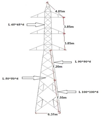
For analytical modal analysis, STAAD has been considered as a suitable tool. The lattice steel transmission tower structure has been modeled as a three-dimensional trussed structure built by 280 nodes joining by 710 beam components using angle steel. Height of the typical tower structure has taken 34m (meters) and base width is considered to be 6.37m (meters), Figure 1 shows. Carbon fiber epoxy (thermoset) is used as a suitable structural member material; specifications of the composite materials are given in Table 1. Rigid connections are given in the members’ joints and structure’s base is rigidly fixed with ground. The slanted members are 100*100*8 cross sectional measure whereas the secondary cross arms (diagonal braces, cross arms etc.) are 75*75*6, 50*50*6 cross sectional measure, Figure 2 shows. The steel angled members mostly carry axial force furthermore; members are connected by weld or bolt. Also, the FE model depends on the accompanying fundamental suppositions as stated below:
Table 1. Suitable composite materials for transmission tower available in market
|
Composite materials |
Young modulus (Gpa) |
Breaking stress (Mpa) |
|
Glass fiber polyamide 6 (thermoplastic) |
29 |
450 |
|
Carbon fiber epoxy (thermoset) |
109 |
1200 |
|
Carbon fiber rigid polyurethane (thermoplastic) |
28 |
427 |
|
Long carbon fiber, nylon66 (thermoplastic) |
36 |
507 |
Figure 1. Configurations details of whole tower structure including nine meters extension along with dimension
Figure 2. The configuration of existing 132 kv transmission tower with necessary dimensions
The lattice steel tower in its working conditions, experiences the impact of the power carrying wires it conveys. The impact of the power carrying wires on natural frequencies cannot be dismissed in actual working conditions. The steel-cored aluminum strand wire "ACSR PANTHER 30/3.00+7/3.00” has been taken as the appropriated power cables, parameters of the wires are shown in Table 2. Since the cross-sectional measurement of the wires is not long as much as the traverse distance between structures, the flexural rigidity nature of the wires is disregarded.
Finite element model of transmission tower is marched modal analysis by using STAAD finite element software. It gives us the six steps of modes. It completely restricted 6 (Six) degrees of freedom. Relationship between frequency (f) and time period (T) is as follows,
$T=\frac{1}{f}$ (5)
Using Eq. (5), we can easily get the six steps of vibration period of the transmission tower model [4]. Modal analysis using STAAD finite element software obtains the six free modes of vibration frequency and time period.
Table 2. Parameters of steel-cored aluminium strand wire "ACSR PANTHER"
|
Parameters |
Conductor wire |
Ground wire |
|
Name of the conductor |
"ACSR PANTHER" 30/3.00+7/3.00 |
GSW 7/3.15 |
|
Area(m²) |
2.615*E-4 |
5.455*E-5 |
|
Diameter(m) |
0.021 |
0.00945 |
|
Weight of the conductor(kg/m) |
0.974 |
0.428 |
|
Ultimate tensile strength(kg) |
9144 |
5710 |
|
Modulus of elasticity(N/m²) |
7.999* E10 |
1.896* E11 |
|
Maximum working span(m) |
335 |
335 |
|
Minimum temperature(°C) |
4 |
4 |
|
Every day temperature(°C) |
32 |
32 |
|
Maximum temperature(°C) |
75 |
53 |
|
Co-efficient of linear expansion(/°C) |
1.78E-05 |
1.15E-05 |
|
Sag (m) |
NA |
4.438 |
|
Factor of safety |
4 |
NA |
|
Initial temperature(°C) |
32 |
4 |
|
Initial wind pressure(kg/m²) |
0 |
0 |
|
Radial ice formation(m) |
0 |
0 |
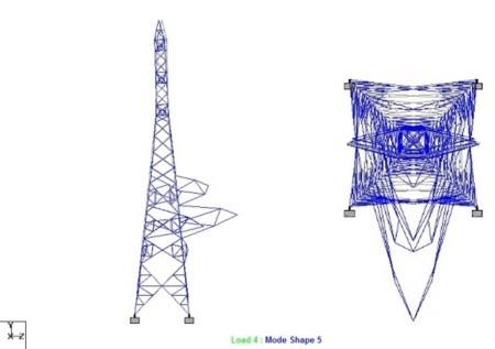
(a) 1st mode of vibration
(b) 2nd mode of vibration
(c) 3rd mode of vibration
(d) 4th mode of vibration
(e) 5th mode of vibration
(f) 6th mode of vibration
Figure 3. Modes of vibration for tower structure obtained from STAAD Pro
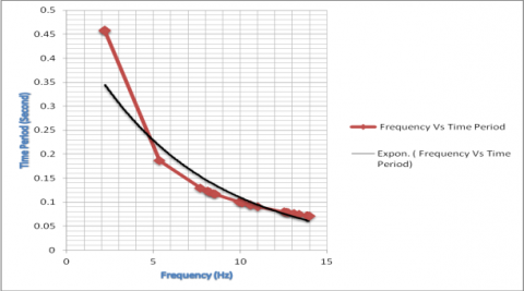
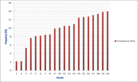
Figure 4 gives the time period vs. frequency curve for the transmission tower; it is showing that the frequency followed inversely with the time period of the lattice composite transmission tower with maximum time period 0.4585 second. Figure 5 showing the variation of frequency with different vibration modes, it indicates the minimum frequency of 2.1808 Hz at first mode. Figure 6 illustrates the maximum displacement vs. frequency curve for the tower. It indicates the maximum displacement occurred at 9.9349 Hz in the amount of 0.094932 meters.
Figure 4. Time period vs. frequency curve for the structure
Figure 5. Variation of frequency with different vibration modes for the structure
Figure 6. Max. Displacement vs. frequency curve for the structure
Electric power sector of India generally uses the formula to nearly estimate the free vibration period (T1) of the tower structure as follows,
$T_1=\frac{0.034H}{\sqrt{(B+b)}}$ (6)
The first free vibration period of the structure from modal analysis is 0.4585 second, but calculating by the Eq (6), it is 0.4357 second. Therefore, the difference between the two periods is 4.97 %. Thus it concludes that the modal analysis results of the tower correspond well with the formula results of the electric power sector. The free vibration period of lattice composite transmission tower is in between (0.007~0.013) H according to the design code. The free vibration period of the composite transmission tower is in between (0.002~0.013) H according to the modal analysis by the standard software.
This paper uses FE software to establish the model of the composite transmission tower structure, studies the dynamic properties the tower, and compared the results with the results obtaining from the experienced formula. The first free vibration period obtained from STAAD is 4.97 % more than that of the period which is calculated by the experienced formula. The bending mode of vibration of composite transmission tower about transverse direction with frequency 8.1394 Hz is found most hazard situation among all the vibration modes. The free vibration period of the composite transmission tower is in between (0.002~0.013) H according to the modal analysis by STAAD, which is in between (0.007~0.013) H according to the design code.
We want to thank Ministry of Human Resource Development (MHRD), INDIA for the funding of this research. We also want to thank to the Director and HOD Mechanical, NIT Agartala, India for their continuous support and motivation.
β wind pressure regulation factor
[S] System stiffness matrix
ν fluctuation influence coefficient
ε oscillating coefficient
γ fluctuating amplifying coefficient
μ wind pressure height coefficient
[M] System mass matrix
H tower height
b width of the root opening
T1 free vibration period
f frequency
B top width of the tower
{X} nodal displacement vector
ω natural frequency
{Ẍ} nodal acceleration vector
[1] Liu, X.F. (2011). The study on modal analysis theory and measurement method for transmission towers. 2011 Second International Conference on Mechanic Automation and Control Engineering, Hohhot, China. https://doi.org/10.1109/MACE.2011.5987317
[2] Momomura, Y., Marukawa, H., Okamura, T., Hongo, E., Ohkuma, T. (1997). Full-scale measurements of wind-induced vibration of a transmission line system in a mountainous area. Journal of Wind Engineering and Industrial Aerodynamics, 72: 241-252. https://doi.org/10.1016/S01676105(97)00240-7
[3] Horr, A.M., Yibulayin, A., Disney, P. (2004). Nonlinear spectral dynamic analysis of guyed towers Part II: Manitoba towers case study. Canada Journal of Civil Engineering, 31: 1061-1076. https://doi.org/10.1139/l04-084
[4] El-Attar, M.M. (1997). Nonlinear dynamics and seismic response of power transmission lines. Ph.D. Dissertation. McMaster University, Hamilton,Ontario, Canada.
[5] Ghobarah, A., Aziz, T.S., El-Attar, M. (1996). Response of transmission lines to multiple support excitation. Engineering Structure, 18: 936-946. https://doi.org/10.1016/S0141-0296(96)00020-X
[6] Loredo-Souza, A.M. (1996). The behavior of transmission lines under high winds. Ph.D. dissertation, The University of Western Ontario, London.
[7] McClure, G., Lapointe, M. (2003). Modeling the structural dynamic response of overhead transmission lines. Computers and Structures, 81: 825-834. https://doi.org/10.1016/S00457949(02)00472-8
[8] Venkatasubramanian, S.H. (1992). Determination of the initiating mode for transmission line galloping. Ph.D. dissertation, Kansas State University, Manhattan, Kansas.
[9] Karoumi, R. (1999). Some modeling aspects in the nonlinear finite element analysis of cable supported bridges. Computers and Structures, 71: 397-412. https://doi.org/10.1016/S0045-7949(98)00244-2
[10] Ozono, S., Maeda, J. (1992). In-plane dynamic interaction between a tower and conductors at lower frequencies. Engineering Structures, 14: 210-216. https://doi.org/10.1016/0141-0296(92)90009-F
[11] Ozono, S., Maeda, J., Makino, M. (1988). Characteristics of in-plane free vibration of transmission line systems. Engineering Structures, 10: 272-280. https://doi.org/10.1016/0141-0296(88)90049-1
[12] Li, H.N., Shi, W.L., Wang, G.X., Jia, L.G. (2005). Simplified models and experimental verification for coupled transmission tower-line system to seismic excitations. Journal of Sound and Vibration, 286: 569-585. https://doi.org/10.1016/j.jsv.2004.10.009
[13] Lantrip, T.B. (1995). Identification of structural characteristics of spun pre-stressed concrete poles using modal testing methods. M.S. Thesis. Birmingham, Alabama: University of Alabama at Birmingham.
[14] Chen, S.E., Ong, C.K., Antonsson, K. (2006). Modal behaviors of spun-cast pre-stressed concrete pole structures. In: Proceeding of IMAC –XXIV, Saint Louis, Missouri, USA.
[15] Polyzois, D., Raftoyiannis, I.G., Ibrahim, S. (1998). Finite elements method for the dynamic analysis of tapered composite poles. Composite Structures, 43: 25-34. https://doi.org/10.1016/S0263-8223(98)00088-9
[16] Dai, K.S., Chen, S.E. (2008). Vibration of spun-cast pre-stressed concrete poles. In: Proceedings IMAC – XXV, Orlando, Florida, USA.