Isam Qasem*![]() | Ahmed A. Hussien
| Ahmed A. Hussien![]() | Khalideh A. Alrawashdeh
| Khalideh A. Alrawashdeh![]() | Pramodkumar S. Kataraki
| Pramodkumar S. Kataraki![]() | Ayub Ahmed Janvekar
| Ayub Ahmed Janvekar![]()
© 2023 IIETA. This article is published by IIETA and is licensed under the CC BY 4.0 license (http://creativecommons.org/licenses/by/4.0/).
OPEN ACCESS
One of the most challenging tasks in machining hard materials is to achieve super high precision with excellent surface finish. The reasons can be addressed due to its properties including high work hardening and poor machinability. Abrasive water jet (AWJ) machining is a multi-operational activity which is proven technology for generating high precision components. The carried-out work mainly intended to showcase the technical parameters which are prime importance in commercial and domestic applications. There parameters include water pressure, traverse speed, abrasive feed rate. These parameters were analyzed with respect to kerf taper and surface roughness on X5CrNi18-10 steel. In the present work key parameters such as traverse speed and outlet pressure were varied from 100 - 200 mm /min and 100 - 200 MPa, respectively. Apart from these two parameters abrasive feed rate was also varied in the range 360 - 540 g/min. Our data from experimental procedures indicate that kerf taper and surface roughness were greatly deflect by variations in the three major parameters; traverse speed, water pressure, and abrasive feed rate. To ensure better comparison of work optimization of process parameter was also carried out. In this optimization response surface methodology and central composite design method was enabled. In addition, all the needed mathematical models were enabled and set of desired contour graphs for tested surface quality are systematically represented. Finally, the kerf taper angle behaviors were also carried out using ANOVA analysis powered by MINITAB 19.
abrasive water jet, ANOVA, surface roughness, kerf taper, X5CrNi18-10 steel
Advanced machining techniques are extensively being adopted for machining of high strength materials such as stainless steels. One of these techniques is the abrasive waterjet (AWJ) machining which simple way of representing it in common terms is a simple high velocity water jet machining process. It finds application to manufacture metallic and non-metallic materials. In addition, it can be considered for abrasive high-pressure water jet machining process, since it can cut high strength and hard materials by directing a high-pressured water [1, 2]. The water jet process offers reduction of cost due to elimination of toxic fumes, recast layers, slag and thermal stresses that do exist in other manufacturing processes. Recent trends of manufacturing indicate the application of water jet machining process to manufacture stone, glass, metals in addition to the manufacturing of paper products, wood, clothes, plastics etc., [3, 4].
There is enormous research going on in development of new and effective high-performance materials, and products are being developed. The challenging aspect is to enable new raw materials for manufacturing process. The main hurdles involved are getting premium surface finish and fulfill all the customer requirements [5]. It is very evident that in case of water jet with super high pressure helps to remove materials in desired qualities, to achieved this feature the jet can be enabled with various micro sized particles such as silica, garnet, aluminum oxide and silicon carbide. The common form of wear can be notices namely; cutting wear and deformation wear. This type of activity will lead to erosion phenomenon at smaller impact angle [6].
Stainless steel is the most and the best material an industrial market has received from decades. There is massive advantage of using stainless steel because of its excellent properties such as high work hardening, corrosion resistance and low thermal conductivity, but a lot of challenges have been faced during machining and cutting of these stainless-steel materials especially while machining by dry cutting tools [7]. The main challenge was to overcome overheating caused mainly because of low thermal conductivity parameter of stainless steel [8]. Therefore, researchers focused more on developing fluid cutting machine such as abrasive water jet [9].
Lot of researchers have discussed the effects of parameters such as depth of cut, type of material, taper angle, surface roughness, wear, kerf taper, abrasive performance and characteristics etc. Kuttan et al. [1] in their review article categorized the parameters affected to AWJ machining into mixing parameters, cutting parameters, abrasive parameters and hydraulic parameters. The researchers utilized the empirical models as well as experimental approaches to find the optimal machining parameters range for abrasive water jet machining processes [10].
Hlaváč et al. [11] focused on the precision of cutting a thick steel (>10 mm) using AWJ. They concluded that the taper angle was varied with the ductility of the steel. They showed the relation between the traverse speed and the high thickness inclination angle and steel plasticity. In addition, they confirm that kerf angle produced by AWJ was related to the traverse rates. Llanto et al. [12] took up research work on the performance testing of abrasive water jet machine by considering stainless steel. Technical parameters involved were traverse speed and material thickness. These variables were focused with respect to kerf taper and material removal rate. It was concluded that minimum kerf taper and material removal rate could be obtained by decreasing the material thickness and low level of traverse speed. A parametric model of cutting depth was established by Miao and Wu [13]. The authors analyzed the process parameters and built the simulation of erosion process of abrasive water jet by using finite element and smoothed particle hydrodynamics methods. Next, the volume of material removal was studied. After verifying the model experimentally, it was concluded that parametric model can be used to fetch optimal process parameters as well as to predict cutting depth. Löschner et al. [14] worked by considering two important parameters namely cutting speeds on surface roughness. The materials used by them was stainless steel of 10mm size, which undergoes abrasive water jet cutting. The roughness parameters were taken for cutting surface geometry at different locations and depth. The results regarding the variation of speed on surface roughness were validated. In addition, authors considered surface quality and occurrence of machining marks. Qiang et al. [15] made research work by considering effect of water pressure, mass fraction of abrasive and size of abrasive on cutting speed. In addition, energy utilization was also involved. The stainless steel was considered as source material and the authors established a mathematical model to study the cutting speed. While energy utilized rate during processing was enabled by abrasive water jet. The concept was based on two areas; inelastic impact mechanics and hydrodynamics. Next, experiments were conducted for the verification of developed model. The results revealed that increasing of cutting speed and decreasing of energy could be done by increasing the water pressure. While the other way is by decreasing of mass fraction with respect to size, which can be considered as negligible. Phokane et al. [16] studied the effect of water pressure, abrasive feed rate, and standoff distance on surface roughness of the miniature brass gear machined by AWJ. They utilized Taguchi’s robust design technique in order to optimize the studied parameters.
Alberdi et al. [17] utilized four process parameters of AWJ to establish a model to predict kerf geometry along a path. The studied parameters were pressure, abrasive mass flow rate, standoff distance, and traverse feed rate. They concluded that the cut surface quality was mainly depended on the traverse feed rate. Selvan et al. [18] took up challenge to work with process factors. These factors include abrasive feed rate, nozzle traverse speed, water pressure as well as standoff distance. The intension was to deal with depth of cut on cast iron by utilizing abrasive waterjet cutting. The main intension of the author was to focus on the depth of cut rather than other parameters. They ensure and validate the data with modified empirical model for get information about the depth of the cut. It was concluded that the modified empirical technique can be used to predict the cutting depth of cast iron within the range of their experiment. Furthermore, there exist direct dependency between depth of cut and mass flow rate. While decrease in depth of cut shall increase standoff distance and nozzle traverse speed. Recently, Alsoufi et al. [19] worked with two parameters namely, surface roughness and micro-hardness. Their team worked with performance of abrasive water jet cutting and outcome reports were compared with laser beam technology. The output data for abrasive water jet cutting method showed good performances as compared with other cutting methods especially for metals. Deaconescu and Deaconescu [20] utilized response surface methodology to analyze the cut surface quality using AWJ in order to reduced time needed for experimenting. Four process parameters (waterjet pressure, grit size, stand-off distance, and traverse speed) were figured out in their experimental research. The machined material was X2 CrNiMo 17-12-2 stainless steel.
The vast spread of literature indicates the importance and significance of optimizing the effect of process parameters over various commercial materials. The most popular choice made by researcher was X5CrNi18-10 steel using abrasive water jet technology. Hence, the present research work takes up the challenge to enhance on similar lines by considering experimental study of performance with main cutting parameters on surface roughness and kerf taper. Moreover, the better a methodology was adopted such as response surface methodology along with central composite design method so that best values of process parameters can be generated. To get further accuracy and clear understanding of various parameters ANOVA analysis was integrated to come up with set of contour graphs for tested surface quality and kerf taper angle.
2.1 Material preparation
Table 1. Mechanical properties of X5CrNi18-10 stainless steel [21]
|
Property |
Value |
|
Tensile strength |
540–750 MPa |
|
Yield strength |
230 MPa |
|
Elongation |
45% |
Table 2. Weight percentage (wt.%) of chemical composition of X5CrNi18-10 stainless steel [21]
|
Chemical composition |
wt.% |
Chemical composition |
wt.% |
|
C |
0.05487 |
Al |
0.00 |
|
Si |
0.64 |
V |
0.046 |
|
Mn |
1.66 |
W |
0.048 |
|
Cr |
18.2 |
Co |
0.40 |
|
Ni |
9.11 |
Nb |
0.013 |
|
Mo |
0.092 |
Pb |
0.015 |
|
Cu |
0.14 |
Sn |
0.00 |
|
Ti |
0.006 |
Fe |
69.7 |
X5CrNi18-10 stainless steel was selected since it possesses superior properties over conventional materials. It has low thermal conductivity and high work hardening rate. The consideration of stainless steel is also due to its vast applications such as in fabrication, chemical processing and in food processing equipment thereby fulfilling the needs of high corrosion resistance [7]. Some of the key mechanical properties of considered X5CrNi18-10 steel are reforested in Table 1.
The samples arranged for experimental tests with 70 mm width, 80 mm length and 7 mm thickness, where the chemical composition of X5CrNi18-10 stainless steel material is represented in Table 2.
2.2 Machine preparation
The machining operation are performed using an abrasive water- jet cutting machine (Jordan Automation), which has accuracy and repeatability of ±0.1mm. The lateral speed is ranged from zero to 15 m/min. The pumping system (HyPrecision 50 Waterjet pump) produces a high-velocity water jet by pressing water up to 445 MPa, and the machine use CNC unit (PCIMC-6A) type, and Nc studio as a CAM software. The machine with the worktable and the pumping system are shown in Figure 1. Whereas the details about abrasive material are shown in Table 3.
Table 3. Quick details of garnet
|
Specification |
Details |
|
Place of Origin |
Jiangsu, China (Mainland) |
|
Material |
Almandine garnet |
|
Color |
Red |
|
Bulk Density |
1.96-2.15 g/cm3 |
|
Brand Name |
Jin Hong |
|
Hardness |
7.5-8.0 Mohs Scale |
|
Abrasive Grain |
80 MESH |
Figure 1. a) AWJ cutting machine. b) Pumping system
Various parameters considered along with the value are indicated in Table 4. The shortlisting for the parameter was based on the type and thickness of the material. Further the selection of the procedure was based on the available built in library in the adopted CNC machine.
Table 4. Constant process parameters
|
Parameter |
Value |
|
Thickness |
7 mm |
|
Stand of distance |
3 mm |
|
Nozzle diameter |
0.79 mm |
|
Orifice diameter |
0.25 mm |
|
Abrasive type |
Garnet |
|
Abrasive grain size |
80 MESH |
|
Impinging angle |
90 degree |
2.3 Measurements procedure
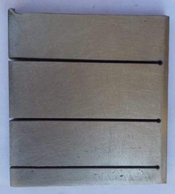
The surfaces produced during abrasive water jet cutting can be divided into three zone. These zones can be distinguished geometrically depending on material properties and cutting process settings. Hloch and Valíček [22] gave suitable naming to the various zones. The team identified zones as initial, the surface cut, and the bottom. On other side, these regions are depending on the cutting speed according to Ma and Deam [23]. The approximate location of the smooth zone was indicated by surface cut region. With the experiment, surface roughness Ra value was considered. This was intended to portion on the cut surface of the smooth cutting zone, which was 3mm in the depth. More information can be notices in Figure 2. A quantitative approach was made to ensure the outcome of surface roughness using selected water jet variables. It includes static characteristics, including the average surface roughness (Ra). The roughness tester RT10 is utilized to measure Ra. Every measurement has been repeated at least three times to calculate the average values of Ra with a cutoff of 0.8 mm. The fluctuation of these measurements was within the accepted margin, which was about 5%. Samples of cutting X5CrNi18-10 stainless steel using abrasive water jet machine are shown in Figure 3 wherein the figure signifies the cut profile of work pieces and denotes the top kerf angle.
Figure 2. Topography of cut surface
Figure 3. Photograph of the stainless workpiece (top view)
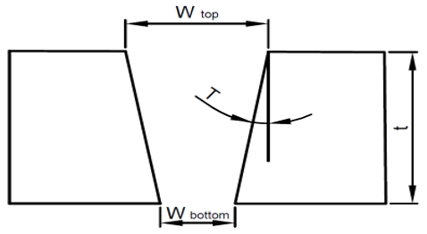
It characterizes the complete geometry of a cut which is as shown in Figure 4. Further, Kerf taper angle was computed from kerf width values using Eq. (1) [24]:
$T=\tan ^{-1}\left(\frac{w_{t o p}-w_{\text {bottom }}}{2 t}\right)$ (1)
In above expression T refers to kerf taper angle (°), while metal thickness is represented by t(mm). Further wtop and wbottom implies to top and bottom kerf width in terms of mm, respectively. Figure 4 indicates a cut profile of material by focusing on top kerf angle. The Kerf taper is one of the parameters that describes the geometry of a cut produced by abrasive water jet, using the taper definition.
Figure 4. Abrasive water jet cut profile
2.4 Utilized parameters and its impact
Present work enables one of the popular methodologies known as RSM i.e., Response Surface Methodology. It is adopted by various researchers to assess the outcomes and performance of manufacturing operations [25]. RSM with central composite design (CCD) experiment is being adopted. The concept of CCD involves factorial design by considering center points. This will boot a group of axial points, which are known as star points. With the use of these information curvature can be made in much better way. The RSM is also a technique for optimizing that is used to integrate multiple independent variables and analyze how their dynamic interactions affect responses.
With available of various methodologies, RSM was shortlisted due to presence of optimal settings for each factor. Thus, the proposed model's makes success in demonstrating various critical information using analysis of variances. The variable levels were restricted to only three levels because of machine configuration. Table 5 shows the information from Level 1 to 3 across factors considered.
Table 5. AWJM cutting parameters their factor and levels
|
Symbol |
Factors |
L1 |
L2 |
L3 |
|
P1 |
Traverse speed, mm/min |
100 |
150 |
200 |
|
P2 |
Abrasive feed rate, g/min |
360 |
450 |
540 |
|
P3 |
Water pressure, MPa |
100 |
150 |
200 |
In this research, AWJM process characteristics have been investigated (surface roughness, Kerf taper angle) using a recommended number of experimental trials. MINITAB 19.0 statistical software is utilized for this experimental investigation [26].
Based on the experimental data, a regression analysis and statistical analysis have been obtained. Using MINITAB 19 software an optimum option was selected to ensure the multilinear stepwise regression analysis to occur. With this prediction was made for the surface roughness as well as for kerf taper. The 2nd order polynomial regression model was adopted for better results [27, 28], which indicated below.
$Y_n=\beta_0+\sum_{i=1}^k \beta_i P_i+\sum_{i=1}^k \beta_{i i} P_i^2+ \\ \sum \sum_{i<j} \beta_{i j} P_i P_j+\in_i$ (2)
where, $Y, P, \beta_0, \beta_i, \beta_{i i}$ and $\beta_{i j}$ are variables for response, factor, free term, linear effect, squared effect, and interaction effect respectively. While the k and n represents the number of factors and response, respectively.
The main intension was to explore the effect of process factors on considered materials. In present case X5CrNi18-10 stainless steel was subjected to abrasive water jet machine. Three aspects where closely monitors namely; traverse speed, abrasive feed rate and water pressure. The impact of parameters influenced on surface roughness as well as kerf taper angle. Table 6 List out experimental data for process parameters based on CCD.
Table 6. Experimental outcomes for surface roughness and Kerf taper angle
|
P1 [mm/min] |
P2 [g/min] |
P3 [MPa] |
Average surface roughness Ra [µm] |
Kerf taper angle [o] |
|
200 |
360 |
200 |
10.93 |
1.97 |
|
150 |
450 |
150 |
12.04 |
2.10 |
|
150 |
450 |
150 |
11.94 |
2.08 |
|
200 |
540 |
200 |
9.76 |
2.57 |
|
150 |
450 |
150 |
12.15 |
2.13 |
|
200 |
450 |
150 |
13.13 |
2.34 |
|
150 |
360 |
150 |
12.62 |
1.78 |
|
150 |
450 |
150 |
12.25 |
2.08 |
|
150 |
450 |
200 |
8.95 |
2.01 |
|
150 |
450 |
150 |
12.09 |
1.98 |
|
100 |
450 |
150 |
9.10 |
1.83 |
|
200 |
360 |
100 |
13.50 |
2.11 |
|
100 |
540 |
100 |
11.03 |
2.20 |
|
150 |
540 |
150 |
11.47 |
2.38 |
|
150 |
450 |
100 |
14.53 |
2.15 |
|
100 |
360 |
100 |
12.15 |
1.60 |
|
200 |
540 |
100 |
13.35 |
2.71 |
|
100 |
540 |
200 |
6.44 |
2.06 |
|
150 |
450 |
150 |
12.31 |
2.05 |
|
100 |
360 |
200 |
8.59 |
1.46 |
3.1 Analysis of variance and fitted regression models
The CCD provides nearly the same results as three-level factorial. A CCD was used for a series of tests, as shown in Table 7 & 8. Other Numerical data such as standard error of estimate, sum of squares of the errors, F statistics and, p value for average surface roughness and Kerf taper in AWJM was also investigated. Using 5% significance levels, If the p value was less than 0.05, the model was considered important (significance probability value), the effects of P1, P2, P3 statistically significant.
According to the analysis, the best model to match the response data is the quadratic model results are validated using a coefficient R², adjusted R², and the Predicted R². These values for a surface roughness are 96.1%, 92.56%, and 70.58% respectively. Table 7 indicate data from ANOVA simulation using quadratic model for surface roughness. Further regression model adopted after narrowing insignificant variables, which can be seen in Eq. (3). This model matches the data very well, as shown in Figure 5.
$R a(\mu m)=5.46+0.1058 P_1+0.0003 P_2+ \\ 0.0143 P_3-0.000395 P_1^2$ (3)
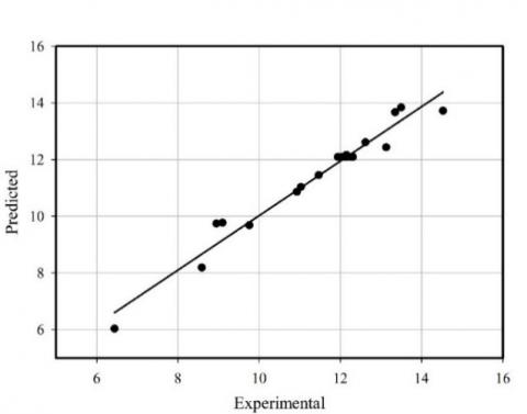
Analysis of variance of Kerf taper angle shows high accurate model with significant level (0.05). Where the R² equal to 99.17%, an adjusted R² is 98.42%, and the Predicted R² 98.90% as shown in Table 8. The quadratic regression model, which containing the significant terms, is in Eq. (4). In addition, Figure 6 illustrated the good agreement between the predicted values of kerf taper angle with the measurements data.
$T\left(^{\circ}\right)=0.180+0.00417 P_1+0.00303 P_2 \\ -0.00173 P_3$ (4)
Table 7. ANOVA for Quadratic model – Average surface roughness
|
Source |
DF |
Adj SS |
Adj MS |
F-Value |
p-value |
|
|
Model |
9 |
70.328 |
7.8143 |
27.40 |
0.000 |
Significant |
|
P1 |
1 |
17.849 |
17.849 |
62.58 |
0.000 |
Significant |
|
P2 |
1 |
3.2948 |
3.2948 |
11.55 |
0.007 |
Significant |
|
P3 |
1 |
39.561 |
39.561 |
138.70 |
0.000 |
Significant |
|
P12 |
1 |
2.6755 |
2.6755 |
9.38 |
0.012 |
Significant |
|
P22 |
1 |
0.0087 |
0.0087 |
0.03 |
0.865 |
|
|
P32 |
1 |
0.3591 |
0.3591 |
1.26 |
0.288 |
|
|
P1P2 |
1 |
0.4753 |
0.4753 |
1.67 |
0.226 |
|
|
P1P3 |
1 |
0.4950 |
0.4950 |
1.74 |
0.217 |
|
|
P2P3 |
1 |
0.5253 |
0.5253 |
1.84 |
0.205 |
|
Figure 5. Variation of data points for predicted and experimental measurements
Table 8. ANOVA for Quadratic model - Kerf taper angle
|
Source |
DF |
Adj SS |
Adj MS |
F-Value |
p-value |
|
|
Model |
9 |
1.6000 |
0.1778 |
132.92 |
0.000 |
Significant |
|
P1 |
1 |
0.6502 |
0.6502 |
486.18 |
0.000 |
Significant |
|
P2 |
1 |
0.9000 |
0.9000 |
672.92 |
0.000 |
Significant |
|
P3 |
1 |
0.0490 |
0.0490 |
36.64 |
0.000 |
Significant |
|
P12 |
1 |
0.0002 |
0.0002 |
0.12 |
0.733 |
|
|
P22 |
1 |
0.0000 |
0.0000 |
0.02 |
0.904 |
|
|
P32 |
1 |
0.0000 |
0.0000 |
0.02 |
0.904 |
|
|
P1P2 |
1 |
0.0000 |
0.0000 |
0.00 |
1.000 |
|
|
P1P3 |
1 |
0.0000 |
0.0000 |
0.00 |
1.000 |
|
|
P2P3 |
1 |
0.0000 |
0.0000 |
0.00 |
1.000 |
|
Figure 6. Comparison of predicted kerf taper angle with experimental measurements
3.2 Impact of process parameters
The variation of average surface roughness across three parameters are indicated with the help of Figure 7. From the plot it can be inferenced that variation of water pressure of abrasive water jet moves inversely to surface roughness. This parameter has a significant effect comparing to abrasive feed rate and traverse speed. For example, when water pressure was varied from 100 to 200 MPa the mean of Ra dips from 13 µm to 9 µm. These results occur due to increase of kinetic energy of the water particles which hit the working metals, so the cutting become perfect with less cavitation and waviness pattern on the cutting surfaces [29].
The same trend can be seen for the effect of abrasive feed rate on average surface roughness, Figure 7. However, the increase of traverse speed produced low surface quality. When cutting process was carried out especially at high traverse speed it was noticed that small quality of materials was behaving very unstable in nature. This action leads to propagation of more uneven and irregular cavities, further significate holes was also observed, over the cutting surfaces [30]. Thus, it can be inferenced that higher traverse speed can lead to more surface roughness. This kind of behavior was noticed immaterial to the stacking configuration [31].
Figure 7. Variation process parameters with mean of surface roughness
In order to find the optimum settings of the process parameters to reach the best surface roughness (minimum value of Ra), contour plots shown in Figure 8 illustrated a relation between surface roughness and other two process factors. For example, Fig. 8-b shows that the best value of Ra in the upper left region where travers speed is at minimum value and at high abrasive feed rate. The result is compatible with Phokane et al. [16]. They improved the surface finish of machined brass gear using AWJ by increasing the water jet pressure and abrasive mass flow rate.
3.3 Performance of process parameters with respect to Kerf taper angle
One of the main objectives of this research was to consider the investigation of effect along the process parameters. This was also intended to include AWJ cutting on kerf taper angle. It can be shown from Figure 9 that high traverse speed is applied to material cutting it leads to higher kerf taper angle than the mean value of kerf taper angle, because of increase in probability of jet deflection [24]. Also, the higher abrasive feed rate caused increasing of the exposure time which more participation of abrasive particles in erosion and penetration (higher material delamination) and low kerf taper angle [32]. While increasing the pressure of water particles led to decrease in kerf taper angle for example, the mean of kerf taper decreases from 2.15° to 1.65° when the water pressure raised from 100 MPa to a value of 200 MPa. This result is due to increase in the mass removal rate for all traverse feed rates according to Alberdi et al. [17]. Next, both water pressure and abrasive feed rate was found out to be more significant impact on kerf taper angle. These results occur because of higher kinetic energy of fluids which hit on the working metals. Gnanavelbabu [29] took lower kerf taper at high water pressure by trimming of Aluminum metal matrix composites. In addition, Figure 10 presents the effect of combination of different two-process factors to kerf taper as a contour plot. This can lead to find the optimum grouping process parameters setting.
Figure 8. Contour plot of surface roughness with a) water pressure and traverse speed , b) abrasive feed rate and traverse speed, and c) water pressure and abrasive feed rate
Figure 9. Variation of process parameters across Kerf taper
Figure 10. Contour plot of kerf taper angle with a) water pressure and traverse speed, b) abrasive feed rate and traverse speed, and c) water pressure and abrasive feed rate
The validation of the predecting models has been done using response optimazer, as shown in Figure 11. The target values for surface roughness and kerf taper angle are 10 µm and 2ο, respectivily. The diviation between predicted and experiment values were ± 8% which is acceptable range of the suggested model. The deviations are due to the influence of the high pressure, cousing wearing of mixing tubes, and particle fragmentation before they escape from the nozzle in the cutting machine.
Figure 11. Validation of quadratic model for surface roughness and kerf taper angle
The experimental research work was carried out by analyzing behavior of X5CrNi18-10 stainless steel cutting surface quality using abrasive water jet machine. Three main AWJ parameters where focused namely; traverse speed, water pressure and abrasive feed rate affected to cutting surface quality were studied. In addition, the statistical optimization, mathematical models, and set of contour graphs were also tested for surface quality and kerf taper angle by using the response surface methodology and central composite design method, and ANOVA analysis, respectively. The major outbreak information indicated that water pressure and abrasive feed rate during cutting metals was inversely proportional to kerf taper angle and mean of surface roughness, whereas increasing traverse speed from 100-200 caused increasing surface roughness and kerf angle about 25% and 20%, respectively. This possible reason can be attributed due to increase in kinetic energy of water particles during cutting process. In addition to that, the effect of abrasive speed on kerf taper angle and mean of surface roughness was insignificant with a little negative effect. Finally, the quadratic models were validated.
[1] Kuttan, A.A., Rajesh, R., Anand, M.D. (2021). Abrasive water jet machining techniques and parameters: A state of the art, open issue challenges and research directions. Journal of the Brazilian Society of Mechanical Sciences and Engineering, 43(4): 1-14. https://doi.org/10.1007/s40430-021-02898-6
[2] Hussien, A.A., Qasem, I., Kataraki P.S., Al-Kouz, W., Janvekar, A.A. (2021). Studying the performance of cutting carbon fibre-reinforced plastic using an abrasive water jet technique. Strojniski Vestnik/Journal of Mechanical Engineering, 67(4): 135-141. https://doi.org/10.5545/sv-jme.2021.7141
[3] Natarajan, Y., Murugesan, P.K., Mohan, M., Khan, S.A.L.A. (2020). Abrasive water jet machining process: A state of art of review. Journal of Manufacturing Processes, 49: 271-322. https://doi.org/10.1016/j.jmapro.2019.11.030
[4] Liu, X., Liang, Z., Wen, G., Yuan, X. (2019). Waterjet machining and research developments: A review. The International Journal of Advanced Manufacturing Technology, 102(5-8): 1257-1335. https://doi.org/10.1007/s00170-018-3094-3
[5] Azhari, A., Schindler, C., Hilbert, K., Godard, C., Kerscher E. (2014). Influence of waterjet peening and smoothing on the material surface and properties of stainless steel 304. Surface and Coatings Technology, 258: 1176-1182. https://doi.org/10.1016/j.surfcoat.2014.07.013
[6] Putz, M., Dix, M., Morczinek, F., Dittrich, M. (2018). Suspension technology for abrasive waterjet (AWJ) cutting of ceramics. Procedia Cirp, 77: 367-370. https://doi.org/10.1016/j.procir.2018.09.037
[7] Korkut, I., Kasap, M., Ciftci, I., Seker, U. (2004). Determination of optimum cutting parameters during machining of AISI 304 austenitic stainless steel. Materials & Design, 25(4): 303-305. https://doi.org/10.1016/j.matdes.2003.10.011
[8] Bedi, S.S., Behera, G.C., Datta, S. (2020). Effects of cutting speed on MQL machining performance of AISI 304 stainless steel using uncoated carbide insert: application potential of coconut oil and rice bran oil as cutting fluids. Arabian Journal for Science and Engineering, 45(11): 8877-8893. https://doi.org/10.1007/s13369-020-04554-y
[9] Ćojbašić, Ž., Petković, D., Shamshirband, S., Tong, C.W., Ch, S., Janković, P., Dučić, N., Baralić, J. (2016). Surface roughness prediction by extreme learning machine constructed with abrasive water jet. Precision Engineering, 43: 86-92. https://doi.org/10.1016/j.precisioneng.2015.06.013
[10] Akkurt, A., Kulekci, M.K., Seker, U., Ercan, F. (2004). Effect of feed rate on surface roughness in abrasive waterjet cutting applications. Journal of Materials Processing Technology, 147(3): 389-396. https://doi.org/10.1016/j.jmatprotec.2004.01.013
[11] Hlaváč, L.M., Hlaváčová, I.M., Geryk, V., Plančár, Š. (2015). Investigation of the taper of kerfs cut in steels by AWJ. The International Journal of Advanced Manufacturing Technology, 77(9): 1811-1818. https://doi.org/10.1007/s00170-014-6578-9
[12] Llanto, J.M., Tolouei-Rad, M., Vafadar, A., Aamir, M. (2021). Impacts of traverse speed and material thickness on abrasive waterjet contour cutting of austenitic stainless steel AISI 304L. Applied Sciences, 11(11): 4925. https://doi.org/10.3390/app11114925
[13] Miao, X., Wu, M. (2020). Modeling of cutting of stainless steel AISI 304 by abrasive water jet. Materials Research Express, 7(8): 086507. https://doi.org/10.1088/2053-1591/abaaca
[14] Löschner, P., Jarosz, K., Niesłony, P. (2016). Investigation of the effect of cutting speed on surface quality in abrasive water jet cutting of 316L stainless steel. Procedia Engineering, 149: 276-282. https://doi.org/10.1016/j.proeng.2016.06.667
[15] Qiang, C., Wang, F., Guo, C. (2020). Study on cutting speed and energy utilization rate in processing stainless steel with abrasive water jet. The International Journal of Advanced Manufacturing Technology, 108: 1875-1886. https://doi.org/10.1007/s00170-020-05536-y
[16] Phokane, T., Gupta, K., Gupta, M.K. (2018). Investigations on surface roughness and tribology of miniature brass gears manufactured by abrasive water jet machining. Proceedings of the Institution of Mechanical Engineers, Part C: Journal of Mechanical Engineering Science, 232(22): 4193-4202. https://doi.org/10.1177/0954406217747913
[17] Alberdi, A., Rivero, A., López de Lacalle, L.N., Etxeberria, I., Suárez, A. (2010). Effect of process parameter on the kerf geometry in abrasive water jet milling. The International Journal of Advanced Manufacturing Technology, 51(5): 467-480. https://doi.org/10.1007/s00170-010-2662-y
[18] Selvan, M.C.P., Raju, N.M.S., Rajavel, R. (2011). Effects of process parameters on depth of cut in abrasive waterjet cutting of cast iron. International Journal of Scientific & Engineering Research, 2(9): 1-5.
[19] Alsoufi, M.S., Suker, D.K., Alsabban, A.S., Azam, S. (2016). Experimental study of surface roughness and micro-hardness obtained by cutting carbon steel with abrasive waterjet and laser beam technologies. American Journal of Mechanical Engineering, 4(5): 173-181. https://doi.org/10.12691/ajme-4-5-2
[20] Deaconescu, A., Deaconescu, T. (2021). Response surface methods used for optimization of abrasive waterjet machining of the stainless steel X2 CrNiMo 17-12-2. Materials, 14(10): 2475. https://doi.org/10.3390/ma14102475
[21] Bringas, J.E. (2002). Handbook of comparative world steel standards. United States: ASTM.
[22] Hloch, S., Valíček, J. (2012). Topographical anomaly on surfaces created by abrasive waterjet. The International Journal of Advanced Manufacturing Technology, 59(5-8): 593-604. https://doi.org/10.1007/s00170-011-3511-3
[23] Ma, C., Deam,R.T. (2006). A correlation for predicting the kerf profile from abrasive water jet cutting. Experimental Thermal and Fluid Science, 30(4): 337-343. https://doi.org/10.1016/j.expthermflusci.2005.08.003
[24] Jagadeesh, B., Dinesh Babu, P., Nalla Mohamed, M., Marimuthu, P. (2018). Experimental investigation and optimization of abrasive water jet cutting parameters for the improvement of cut quality in carbon fiber reinforced plastic laminates. Journal of Industrial Textiles, 48(1): 178-200. https://doi.org/10.1177/1528083717725911
[25] Hang, Y., Qu, M., Ukkusuri, S. (2011). Optimizing the design of a solar cooling system using central composite design techniques. Energy and Buildings, 43(4): 988-994. https://doi.org/10.1016/j.enbuild.2010.12.024
[26] Hanrahan, G., Lu, K. (2006). Application of factorial and response surface methodology in modern experimental design and optimization. Critical Reviews in Analytical Chemistry, 36(3-4): 141-151. https://doi.org/10.1080/10408340600969478
[27] Çaydaş, U., Hascalık, A. (2008). A study on surface roughness in abrasive waterjet machining process using artificial neural networks and regression analysis method. Journal of Materials Processing Technology, 202(1-3): 574-582. https://doi.org/10.1016/j.jmatprotec.2007.10.024
[28] Montgomery, D.C., Peck, E.A., Vining, G.G. (2021). Introduction to Linear Regression Analysis. John Wiley & Sons.
[29] Gnanavelbabu, A., Rajkumar, K., Saravanan, P. (2018). Investigation on the cutting quality characteristics of abrasive water jet machining of AA6061-B4C-hBN hybrid metal matrix composites. Materials and Manufacturing Processes, 33(12): 1313-1323. https://doi.org/10.1080/10426914.2018.1453146
[30] Pahuja, R., Ramulu, M. (2019). Surface quality monitoring in abrasive water jet machining of Ti6Al4V–CFRP stacks through wavelet packet analysis of acoustic emission signals. The International Journal of Advanced Manufacturing Technology, 104(9): 4091-4104. https://doi.org/10.1007/s00170-019-04177-0
[31] MM, I.W., Azmi, A., Lee, C., Mansor, A. (2018). Kerf taper and delamination damage minimization of FRP hybrid composites under abrasive water-jet machining. The International Journal of Advanced Manufacturing Technology, 94(5): 1727-1744. https://doi.org/10.1007/s00170-016-9669-y
[32] Srinivasu, D.S., Axinte, D.A., Shipway, P.H., Folkes, J. (2009). Influence of kinematic operating parameters on kerf geometry in abrasive waterjet machining of silicon carbide ceramics. International Journal of Machine Tools and Manufacture, 49(14): 1077-1088. https://doi.org/10.1016/j.ijmachtools.2009.07.007