Noor Alhuda Sami Aljabbri | Mohammed Noori Hussein* | Ali Abdulmohsin Khamees
© 2021 IIETA. This article is published by IIETA and is licensed under the CC BY 4.0 license (http://creativecommons.org/licenses/by/4.0/).
OPEN ACCESS
Fire or high temperature is a serious issue to ultra-high-strength concrete (UHSC). Strength reduction of UHPCs may amount to as high as 80 percent after exposure to 800℃. A sum of four UHSC mixes was synthesized and evaluated in this study after getting exposed to extreme temperatures that reach 1000°C. Steel and polypropylene (PP) fibers were used in this experiment. A total of four mixes were made of UHSC without fibres as a control mix (UHSC-0), UHSC with 2% steel fibres (UHSC-S), UHSC with 2% PP fibres (UHSC-P) and UHSC with 1% steel fibres + 1% PP fibres (UHSC-SP). Workability, direct tensile strength, compressive strength, and splitting tensile strength were examined. Particularly, emphasis was devoted to explosive spalling since UHPCs are typically of compact structure and hence more prone to explosive spalling than other concretes. It was determined that the mixture UHSC-SP had high fire resistance. Following exposure to 1000℃, this mixture preserved a residual compressive strength of 36 MPa, splitting tensile strength of 1.62 MPa and direct tensile strength of 0.8 MPa. On the other hand, UHSC-P also had good fire resistance while UHSC-0 and UHSC-S experienced explosive spalling after heating above 200ᴼC. The incorporation of steel fibers in UHSC-S and UHSC-SP mixtures reveals higher tensile and compressive strength findings at different elevated temperatures as compared to UHSC-0 and UHSC-P. In addition, the result of direct tensile strength appears to be lower than splitting tensile strength at different raised temperatures.
UHPCs, fibers, temperature effect, mechanical properties
UHSC is a cementitious composite material with a higher percentage of discontinuous internal fiber reinforcement, an optimal granular elements gradation and a water-to-cementitious material ratio of below 0.25. The tensile and compressive strengths of UHPC are high, whereas the permeability is minimal [1]. Many nations are concerned about the premature and early deterioration of reinforced concrete structures, as it may impose a direct financial strain on future economies and endanger public safety. In order to manage this issue to a minimum while maintaining the structural adequacy and core functions of these fortified concrete structures, the extent and frequency of repair interventions must be restricted to the minimum level [2].
Many concrete structures that are subject to strong loads and changes in temperature, such as dams, retaining walls, and others, need types of strong concrete that have better specifications than ordinary concrete. ultra-high-strength concrete will be very suitable for these types of constructions [3-5].
There are three types of ultra-high-strength concrete: (1) reactive powder concrete (RPC), (2) ultra-high-performance concrete (UHPC), and (3) self-compacted reactive powder concrete (SCRPC). Nonetheless, the link between UHPC and NSC must be evaluated before UHSC may be widely utilised as a repair material. The bond must have sufficient strength to withstand stress caused by mechanical loading or thermal impacts while also providing long-term performance. Based on these factors, this study discusses the research of the durability of the interface between ultra-high-performance concrete toppings and variable surface textured normal strength concrete substrates under a range of stress states and changing freeze-thaw regimes. The experiments conducted to assess the bond strength between an overlay material and a concrete substrate are classified into three categories based on the stress documented: A combination of shear and compression stresses, tension and pure shear [6, 7].
The development of ultra-high-strength concrete is driven by the demand for high-strength construction materials (UHSC). According to Chinese standards [8], ultra-high-strength concrete is defined as concrete with a strength greater than 100 MPa. As stated by another study, UHSC refers to concrete with a compressive strength higher than 100 MPa [9]. UHSC is distinguished by its high cement and silica fume content, as well as its low water/binder ratio. To achieve superior mechanical and durability features, aggregate grading and high-temperature curing should be improved. For the time being, UHSC is deemed as a promising material for precast and prestressed concrete members. Thus, nuclear and industrial waste storage facilities can be built with these materials [10].
In the recent period, the use of UHSC has become essential to improve structures characteristics. in this type of concrete, the pozzolanic materials are a major part of its components. Often industrial and agro residual wastes are used as a partial replacement for cement and the concrete so produced is referred to as blended cement concrete. Rice husk ash, palm oil fuel ash, and sugarcane bagasse ash are the most frequent agricultural wastes utilized as pozzolans. Due to the pozzolanic reaction with the calcium hydroxide formed during cement primary hydration, the inclusion of these has a positive impact on the mechanical and durability properties of concrete [11-14].
The main research program’s goals are to: first, produce UHSC with high fire resistance using locally available materials, and second, investigate the tensile and compressive behavior of UHSC at various elevated temperatures.
Ordinary Portland cement, silica fume, sand, and gravel were employed as ultra-high-strength concrete (UHSC) constituent materials in this study. Moreover, a superplasticizer was used to verify that the UHSC was workable. Finally, to maximize the mixture’s packing density, these constituent elements’ proportions were carefully modified.
2.1 Cement
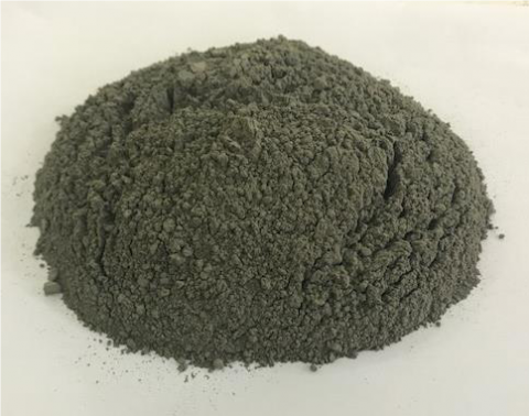
In this research, the Tasluja type’s ordinary Portland cement (OPC) was utilized, which met the standards of EN 197-1:2011 [15]. The binder in UHSC is cement paste, which reacts with mineral components and holds together the aggregate (micron fine, fine) to form a solid mass. Therefore, the quantity and quality of UHSC’s ingredients determine its properties. As cement has the largest unit cost and is the most active component of UHSC, its choice and careful application are critical for achieving the most cost-effective balance of attributes in the UHSC combination. The reason for choosing Tasluja cement is that various tests reveal that Tasluja cement has better concrete strength than other types available in the market. Tasluja cement is seen in Figure 1, where its chemical parameters are recorded in Table 1.
Figure 1. Tasluja cement
Table 1. Mineral compositions of Tasluja cement
|
Compositions |
OPC (%) |
Compositions |
OPC (%) |
|
SiO2 |
20.59 |
Loss of Ignition |
0.8 |
|
Al2O3 |
5.92 |
Insoluble Residue |
1.75 |
|
Fe2O3 |
3.29 |
C3S |
64.68 |
|
CaO |
64.16 |
C2S |
23.2 |
|
MgO |
2.20 |
C3A |
5.15 |
|
SO3 |
2.21 |
C3AF |
9.97 |
|
Free Lime |
0.76 |
|
|
2.2 Silica fume
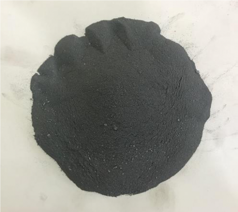
As illustrated in Figure 2, grey densified silica fume type (MegaAdd MS) was utilized, which had a specific gravity of 2.40, a bulk density of 600 kg/m3, and oversize particles retained on a 45-micron filter. When high-purity quartz is reduced with coke and wood chips or coal in an electric arc furnace to manufacture ferrosilicon alloys or silicon metal, silica fume is produced as a byproduct.
The amount of amorphous silicon dioxide in the silica fume which condenses from the furnace gases is extremely high, and it is made up of very fine spherical particles. Silica fume, also called micro silica, is the ferrosilicon and silicon alloy industries’ byproduct, and it contains about 90% amorphous silicon dioxide. Because of the materials’ pozzolanic potential, they have been successfully used as an additive in concrete production. Due to its high pozzolanic reactivity, micro silica was initially used as a cement substitute. However, as more data from the laboratory and field became available, the material began to be used as a supplementary cementitious component, providing improved performance in both fresh and hardened stages.
Figure 2. Grey densified silica fume
2.3 Aggregate
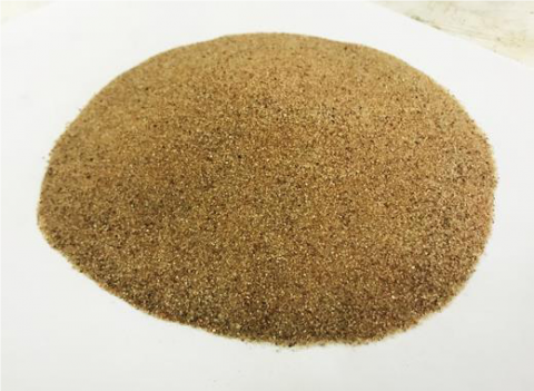
Fine and coarse aggregate from Basrah Quarries has been employed in this research. Zubair provided the fine aggregate in Figure 3 with a maximum size of 1.18 mm. The characteristics of course and fine aggregate employed in this investigation are shown in Table 2. Sieve analysis of fine aggregate was done according to BS 882: 199 2 as presented in Figure 4. The proportions of the different sizes of particles making up the aggregate are found by sieving and are known as the 'grading' of the aggregate: the grading is given in terms of the percentage by mass passing the various sieves. The grading and compare it with IQS [16] (Table 3).
Table 2. Properties of course and fine aggregate
|
Materials |
Specific gravity (g/cm3) |
Absorption |
|
Fine Aggregate |
2.64 |
1.5% |
Table 3. Sieve analysis
|
Sieve size |
Returned (%) |
IQS Zone III |
|
10(mm) |
0 |
100 |
|
4.75(mm) |
2 |
90-100 |
|
2.36(mm) |
13 |
85-100 |
|
1.18(mm) |
20 |
75-100 |
|
600(µm) |
20 |
60-79 |
|
300(µm) |
24 |
12-40 |
|
150(µm) |
18 |
0-10 |
|
pan |
3 |
---- |
Figure 3. Zubair sand
Figure 4. Sieve analysis
2.4 Water
The main considerations on the quality of mixing water are connected to performance in both fresh and hardened states. In this experiment, we used water with a PH of roughly 7 (R.O water) so that the mix design is not affected by the high or low value of PH. In the manufacture of concrete, the quality of the water is critical. Impurities in the water can impact the cement’s ability to set, as well as the strength and longevity of the concrete.
2.5 Superplasticizer
Figure 5. Sika Visco Crete Hi-Tech 1316 (superplasticizer)
Figure 5 shows the superplasticizer utilized in this investigation, Sika ViscoCrete Hi-Tech 1316. Sika ViscoCrete is a polymer-based on modified polycarboxylates that has a specific gravity of 1.123 at 25°C. The application of a superplasticizer improves the combinations’ workability. The extremely high levels of water reduction feasible allow for significant strength gains. All varieties of regular Portland cement, as well as alternative materials such as PFA, GGBFS, and silica fume, can be used with Sika ViscoCrete Hi-Tech 1316.
A wide range of combination compositions could be used to make ultra-high-strength concrete. The UHSC mix is primarily a series of estimates, calculations, and tests/trials to obtain reasonably excellent concrete qualities such as the amount of superplasticizer and water/binder ratio in order to achieve acceptable concrete workability. The range of cement concentration in the production of UHSC varies between 800 and 1000 kg/m3 in order to generate UHSC having a compressive strength between 100 and 180 MPa [17]. The ideal ratio of silica fume to cement is found to be between 20% and 30% [18]. It is best to use fine aggregate having 2.66 specific gravity [19]. The water-to-binder (W/B) ratio was lowered to 0.14-0.18 [20]. The dosage of superplasticizer varies between 3.0% and 4.90% by mass of binder [21]. The matrix’s composition was optimized using these ranges. In experimental batches, the qualities of various basic elements’ combinations (sand, cement, superplasticizer and water) were contrasted. The most promising fundamental component combination has been chosen.
UHSC mix used in this research has a binder content of 1120 kg/m3, silica fume ratio of 17%, water/binder ratio of 0.20, sand with a maximum size of 0.6mm, and superplasticizer dosage of 3% by mass of binder in addition to different percent of steel and polypropylene fiber. Four mixes of UHSC were used in this study, UHSC-0 (without steel and PP fiber), UHSC-S (with 2% steel fiber), UHSC-P (with 2% PP fiber), and UHSC-SP (with 1% steel fiber + 1% PP fiber). Table 4 shows the UHSC mix proportions employed in this investigation.
Here:
Table 4. Mix proportions of UHSC & NC employed in the current research
|
Materials (kg/m3) |
UHSC-0 |
UHSC-S |
UHSC-P |
UHSC-SP |
|
Cement |
930.1 |
930.1 |
930.1 |
930.1 |
|
Silica fume |
193.7 |
193.7 |
193.7 |
193.7 |
|
Sand |
903 |
903 |
903 |
903 |
|
Gravel |
|
|
|
|
|
Water |
201.6 |
201.6 |
201.6 |
201.6 |
|
Superplasticizer |
32.9 |
32.9 |
32.9 |
32.9 |
|
Steel Fiber |
|
151 |
|
77 |
|
PP Fiber |
|
|
19.1 |
8.7 |
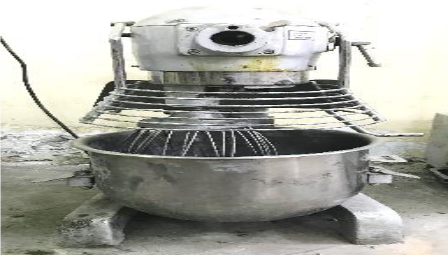
Mixing of UHSC was done using a cement mortar type mixer as shown in Figure 6 as below steps:
Figure 6. Cement mortar mixer
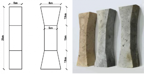
For each mixture, 15 cubes (50×50×50) mm for compressive strength test and 12 cylinders (100dia.×200) for splitting tensile test, and 15 dumbbell shape spacemen for direct tensile strength were prepared. After casting in the appropriate molds, all specimens were kept in a humid atmosphere for 24 hours before being demolded. Following demolding, at room temperature (27°C), the specimens were cured in water until they were needed for testing (see Figures 7 and 8). All the sizes of samples are meeting the ASTM C109 / C109M [22].
Figure 7. Direct tensile test specimen
Figure 8. (a) Three gang 50mm cube mould with UHSC sample, (b) Splitting tensile test specimen
5.1 Workability of fresh concrete
The flow of hydraulic cement mortar test was conducted relying on ASTM C 1437 to ensure the mix was flowable when cast into the joint. UHSC mix was devised to have flow in the favorable 180–220 mm range (see Figure 9) [23, 24].
Figure 9. Flow of hydraulic cement mortar test for UHSC
As presented in Figure 10, the test showed that the inclusion of the steel and polypropylene fiber decreases the workability of the UHSC when compared with UHSC-0 (without fiber) with slump flow values of 091, 081, 061 and 071 mm for UHSC-0, UHSC-S, UHSC-P, and UHSC-SP, respectively. In addition, it is clear from the result that UHSC-P has lower workability than UHSC-S. The decline in workability could be due to the fact that the amount of fiber in a mix has an impact on consistency and slump. The fiber’s surface area is an aspect to consider here. The fibers should also be coated with mortar (cement and sand). The impact on workability will be larger if the mortar fraction is inadequate. More fibers necessitate the use of more mortar. Almost all studies on the interfacial microstructure of SFRC up to this point have been conducted after a pull-out test [18, 25-27]. By studying the remaining hydrated cement paste or mortar on the surface of steel fiber following a pull-out test, they were able to determine the bond characteristic of fiber reinforced concrete. SEM pictures of the microstructure of the fiber surface and the hydrated cement matrix are shown in Figures 11a, b. The steel fiber side surface has been covered with heavily hydrated cement matrix, as shown in the figures. It was also discovered that the cement matrix or mortar adhered to the steel fiber surface. This case demonstrated that the steel fiber surface and the hydrated cement matrix have a strong connection. Figure 12 shows a SEM image of the top shattered surface of SFRC. It's also obvious that a dense matrix formed surrounding the steel-fiber.
Figure 10. Flow of hydraulic cement mortar values for UHSC mixes
Figure 11. Microstructure of SFRC by SEM, magnification: (a) 100 lm; (b) 50 lm (1: steel fiber side surface, 2: hydrated cement matrix)
Figure 12. Microstructure of SFRC by SEM, magnification: 100 lm; (1: steel fiber top surface, 2: hydrated cement matrix
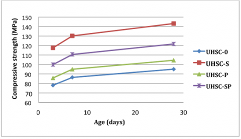
5.2 Compressive strength
A cube specimen with the size of 50 × 50 × 50 mm were tested for compressive strength for UHSC mixes comprising UHSC-0, UHSC-S, UHSC-P, and UHSC-SP. The specimens were tested at 3, 7, and 28 days after curing in water, accordingly. The UHSC mixtures’ compressive strength is shown in Figure 13 and Table 5. UHSC-0 had the least compressive strength of 78 MPa after three days, whereas UHSC-S had the most compressive strength of 143.2 MPa after 28 days. Thus, steel fiber and polypropylene fiber addition have a substantial impact on the strength and UHSC mixes’ strength development characteristics in comparison to the control mix having only OPC, as shown by the overall findings. Meanwhile, the findings demonstrate that UHSC with steel fiber has the most compressive strength compared to the UHSC with polypropylene fibers and control mix.
Figure 13. Influence of steel and polypropylene fibers on compressive strength development of UHSC
Table 5. Compressive strength values for UHSC mixes Compressive strength (MPa)
|
Age(days) |
UHSC-0 |
UHSC-S |
UHSC-P |
UHSC-SP |
|
3 |
78.00 |
117.57 |
85.72 |
99.84 |
|
7 |
86.36 |
130.18 |
94.91 |
110.55 |
|
28 |
95.00 |
143.20 |
104.40 |
121.60 |
5.2.1 The elevated temperature’s effect on the compressive strength of UHSC mixes
The specimens without PP fibers were only investigated at 200°C and room temperature due to serious explosive spalling when heated above 400°C. However, at 200°C, it can be shown that the compressive strength of all four mixes improved when compared to room temperature. The explanation for this might be that the UHPC specimen’s tight structure prevented high-pressure moisture from escaping, resulting in an “internal autoclaving”, enclosed high-temperature or high-pressure curing environment [28]. Furthermore, because active SiO2 is present from silica fume, this curing environment significantly increased both pozzolanic reactions and cement hydration, producing more C-SH gel. As a result, the C-S-H gel was converted into tobermorite and xonotlite, resulting in a more compact internal structure of the specimen with increased compressive strength.
As observed under room and 200°C temperatures, the UHSC-S had much greater toughness and ductility compared to the other concrete. The explanation for this is that at room temperature, the UHSC-S reinforced with steel fibers exhibited a relatively high compressive strength. At room temperature, UHSC-P displays ductile damage, but the damage was brittle at temperatures of 200, 400, and 600°C. It was because the PP fibers made the UHSC-P more ductile at room temperature. When heated to 200°C or higher, however, the melted PP fibers caused the concrete’s ductility to deteriorate.
In comparison to UHSC-P, UHSC-SP has greater compressive strength at all temperatures. Figure 14 and Table 6 show the connections between temperature and compressive strength for the four concretes. The compressive strength of UHSC-SP and UHSC-P increased as the target temperature raised from 27°C to 400°C. As pozzolanic reactions persisted under the high-pressure and high-temperature environment, more C-S-H gel was created and converted into xonotlite and bermorite for UHSC-SP and UHSC-P from 200ᴼC to 400ᴼC. Furthermore, the bound water’s evaporation compacted and hardened the cement paste. PP fibers also melted entirely at this point, considerably reducing vapour pressure. All of this helped to improve the compressive strength of the UHSCP and UHSC-SP. In comparison, from 400°C - 800°C, the strength of both concretes decreased. Because a significant amount of C-S-H was converted to C3S and C2S, and SiO2 was converted to Si2O2, the paste’s porosity increased. At 800°C, the C-SH was entirely decomposed, while the CaCO3 just began to decompose, resulting in reduced internal structure compactness and a large number of small cracks on the specimen’s surfaces. Moreover, at this phase, the mismatching volume expansion between the aggregate and cement paste also had a significant influence in lowering the concrete’s mechanical performance. The strength of UHSC-SP and UHSC-P remained about the same temperature from 800ᴼC to 1000ᴼC.
Figure 14. At 28 days’ edge, elevated temperature’s impact on compressive strength of UHSC mixes
Table 6. Compressive strength values for UHSC mixes at the edge of 28 days
|
|
Compressive Strength (MPa) |
|||
|
Temperature (℃) |
UHSC -0 |
UHSC -S |
UHSC -P |
UHSC -SP |
|
27℃ |
95 |
143.2 |
104 |
121.6 |
|
200℃ |
98 |
148 |
107 |
125.2 |
|
400℃ |
- |
- |
84.8 |
127.6 |
|
600℃ |
- |
- |
70.8 |
91.2 |
|
800℃ |
- |
- |
46 |
52.8 |
|
1000℃ |
- |
- |
30 |
36 |
5.3 Splitting tensile strength
Figure 15 and Table 7 show the UHSC mixes’ split tensile strength at increased temperatures and room temperature. Compared to UHSC at 27℃, the split tensile strength of UHSC at 200℃ rises significantly. When all UHSC specimens were subjected to 200℃, an increase in split tensile strength was seen.
The formation of secondary hydrated and conversion of residual unhydrated cement grains that hydrated drastically forming a secondary hydrated gel with the active participation of silica fume at this temperature is responsible for the substantial improvement in UHSC strength for all fiber dosages. As seen in Figure 16, the increase in strength could be attributable to a bonding effect between the matrix and the fiber. UHSC-0 and UHSC-S erupted owing to a lack of capillary activities at 400℃, as seen in Figure 17. In comparison, the tensile strength of UHSC-P decreased because of a melted channels’ dense network formed by the evaporation of fibers at high temperatures, which accumulate in a single place and lead to cracks. This causes the UHSCP specimen to fail abruptly under tensile loading.
The UHSC-SP, on the other hand, has high strength at 400℃ because of the autoclave effect and the production of stronger and shorter siloxane elements, which produces a strong improvement in the range of temperatures of 250-350℃.
Figure 15. The influence of elevated temperature on splitting tensile strength of UHSC mixes at the edge of 28days
At 600℃, 800℃ and 1000℃, all UHSC mixes undergo a reduction in tensile strength. The quarzitic material’s phase change causes the maximum reduction in tensile strength at 800℃. The tetrahedral chains of quartz molecules extend and reorient as the temperature rises, resulting in a considerable increase in volume, which in turn leads to radial cracking around the particle’s perimeter in a heated specimen.
Figure 16. The impact of elevated temperature on the direct tensile strength of UHSC mixes at the edge of 28 days
Figure 17. Explosive spalling of UHSC-S under 400℃
Table 7. Splitting tensile strength values for UHSC mixes at the edge of 28days
|
|
Compressive Strength (MPa) |
|||
|
Temperature (ᴼC) |
UHSC -0 |
UHSC -S |
UHSC -P |
UHSC -SP |
|
27ᴼC |
4 |
11.59 |
7.64 |
10.66 |
|
200ᴼC |
4.23 |
12.8 |
8.85 |
11.73 |
|
400ᴼC |
- |
- |
7.32 |
14.55 |
|
600ᴼC |
- |
- |
2.76 |
6.81 |
|
800ᴼC |
- |
- |
1.85 |
2.87 |
|
1000ᴼC |
- |
- |
1.18 |
1.62 |
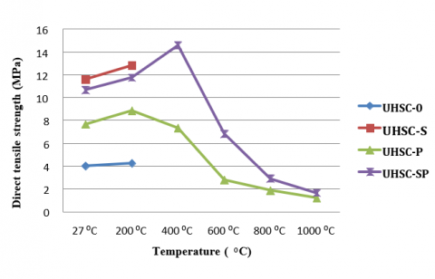
5.4 Direct tensile test
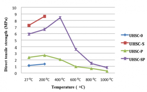
The direct tensile strength results of UHSC mixes at room temperature and elevated temperatures are displayed in Figure 18 and Table 8. It is clear from the result that there is a big gap between the direct tensile strength of UHSC contain steel fiber and the other mixes of UHSC without steel fiber, which shows that the steel fibers’ inclusion increases the direct tensile strength much higher as compared to the inclusion of PP fibers.
Table 8. Direct tensile strength values for UHSC mixes at the edge of 28 days
|
|
Compressive Strength (MPa) |
|||
|
Temperature (ᴼC) |
UHSC -0 |
UHSC -S |
UHSC -P |
UHSC -SP |
|
27ᴼC |
1.1 |
7.25 |
2.35 |
5.9 |
|
200ᴼC |
1.35 |
8.62 |
2.68 |
6.62 |
|
400ᴼC |
- |
- |
2.04 |
8.4 |
|
600ᴼC |
- |
- |
0.94 |
3.57 |
|
800ᴼC |
- |
- |
0.66 |
1.43 |
|
1000ᴼC |
- |
- |
0.27 |
0.8 |
Figure 18. UHSC color change at elevated temperatures
The direct tensile strength of UHSC at 200℃ significantly increases as opposed to UHSC at 27℃. When all UHSC specimens were subjected to 200℃, the split tensile strength rose. The formation of secondary hydrated and transformation of residual unhydrated cement grains that drastically hydrated forming a secondary hydrated gel with the active participation of silica fume at this temperature is responsible for the substantial improvement in the strength of UHSC for all fiber dosages. As seen in Figure 13, the increase in strength could be attributable to a bonding effect between the matrix and the fiber. UHSC-0 and UHSC-S erupted at 400℃ due to a lack of capillary actions. In contrast, the tensile strength of UHSC-P diminishes due to a dense network of melted channels formed by the fibers’ evaporation at elevated temperatures, which accumulate at one place, leading to cracks. This causes the UHSCP specimen to fail abruptly under direct tensile loading. Under elevated temperatures, Figure 18 illustrates the color difference between the UHSC mixtures.
5.5 Mass loss
Gas escape from heated UHPCs and water evaporation is referred to as mass loss in this study. Figure 19 depicts the relationship between the temperature and mass loss for all of the mixtures. Under 200°C, all mixtures showed a negligible mass loss, showing that the UHPC specimens had a very compact structure that prevented vapour from escaping.
Due to the serious explosion, data for UHSC-0 and UHSC-S, as well as concretes, were not collected over 200°C. Both the UHSC-0 and the UHSC-S specimens underwent 0.35% and 0.98% mass loss, respectively, when heated to 200°C. These results demonstrate that steel fiber had a small effect on mass loss of UHPCs exposed to increased temperatures below 200°C. Between 200°C and 400°C, the mass loss of the other two mixtures comprising PP and steel fibers risen sharply. The reason for this was that the PP fibers melting at 165°C created an escaping channels’ network for the vapour. In contrast, the majority of the vapour originated from bound and capillary water between 200°C and 400°C. At temperatures ranging from 360 to 400°C, PP might degrade into several volatiles, for instance, Propylene and Pentane, contributing to the mass loss. The mass loss raised marginally as the temperature raised from 400°C to 1,000°C, peaking at about 12%.
Figure 19. Mass loss under different elevated temperatures
This study reports the experimental results on the production of UHSC with compressive strength greater than 100 MPa under a normal curing regime and investigate the bond behavior between normal concrete (NC) substrate and UHSC as the repair material by employing the splitting and slant shear tests to calculate the bond strength in indirect tension and shear, respectively. The following conclusions are drawn:
[1] Graybeal, B. (2011). Ultra-high performance concrete. (No. FHWA-HRT-11-038). https://rosap.ntl.bts.gov/view/dot/40919
[2] Denarié, E., Brühwiler, E. (2006). Structural rehabilitations with ultra-high performance fibre reinforced concretes (UHPFRC). Restoration of buildings and monuments= Bauinstandsetzen und Baudenkmalpflege, 12(5/6): 453-468.
[3] Kadhim, M., Alfatlawi, T., Hussein, M. (2021). Experimental and nonlinear analysis of cracking in concrete arch dams due to seismic uplift pressure variations. International Journal of Engineering, 34(5): 1156-1166. https://dx.doi.org/10.5829/ije.2021.34.05b.09
[4] Alfatlawi, T.J.M., Kadhim, M.J., Hussein, M.N. (2021). Relation between cracks behavior and curvature in cracked concrete arch dam under earthquake. Materials Today: Proceedings. https://doi.org/10.1016/j.matpr.2021.02.248
[5] Hussein, M.N., Alfatlawi, T.J.M., Kadhim, M.J. (2021). XFEM analysis of concrete arch dam to assess deformations and propagation of artificial crack due to the combination of earthquake and uplift pressure. In Journal of Physics: Conference Series, 1773(1): 012031. https://doi.org/10.1088/1742-6596/1773/1/012031
[6] Espeche, A.D., León, J. (2011). Estimation of bond strength envelopes for old-to-new concrete interfaces based on a cylinder splitting test. Construction and Building Materials, 25(3): 1222-1235. https://doi.org/10.1016/j.conbuildmat.2010.09.032
[7] Momayez, A., Ehsani, M.R., Ramezanianpour, A.A., Rajaie, H. (2005). Comparison of methods for evaluating bond strength between concrete substrate and repair materials. Cement and Concrete Research, 35(4): 748-757. https://doi.org/10.1016/j.cemconres.2004.05.027
[8] Press, C.B.I. (2011). Specification for Mix Proportion Design of Ordinary Concrete, JGJ55-2011. https://www.codeofchina.com/standard/JGJ55-2011.html.
[9] Fardis, M.N. (2011). Innovative materials and techniques in concrete construction: ACES Workshop. Springer Science & Business Media.
[10] Richard, P., Cheyrezy, M. (1995). Composition of reactive powder concretes. Cement and Concrete Research, 25(7): 1501-1511. https://doi.org/10.1016/0008-8846(95)00144-2
[11] Rajasekar, A., Arunachalam, K., Kottaisamy, M., Saraswathy, V. (2018). Durability characteristics of Ultra High Strength Concrete with treated sugarcane bagasse ash. Construction and Building Materials, 171: 350-356. https://doi.org/10.1016/j.conbuildmat.2018.03.140
[12] Chindaprasirt, P., Kroehong, W., Damrongwiriyanupap, N., Suriyo, W., Jaturapitakkul, C. (2020). Mechanical properties, chloride resistance and microstructure of Portland fly ash cement concrete containing high volume bagasse ash. Journal of Building Engineering, 31: 101415. https://doi.org/10.1016/j.jobe.2020.101415
[13] Alhashimi, M.N.H. (2014). Performance of blended cement concrete by using palm oil shells as coarse aggregate. Doctoral dissertation, Universiti Teknologi Malaysia.
[14] Shi, C., Day, R.L. (2000). Pozzolanic reaction in the presence of chemical activators: Part I. Reaction kinetics. Cement and Concrete Research, 30(1): 51-58. https://doi.org/10.1016/S0008-8846(99)00205-7
[15] Standard, E. (2000). Cement-Part 1: Composition, specifications and conformity criteria for common cements.
[16] Abed, A.A., Kamal, I.M. (2020). Factorial Design for Studying the Properties of Recycled Aggregate Concrete Exposed to Aggressive Media.
[17] Cwirzen, A., Penttala, V., Cwirzen, K. (2008). The effect of heat treatment on the salt freeze-thaw durability of UHSC. In Proceedings of the 2nd International Symposium on Ultra High Performance Concrete, Kassel, Germany, pp. 221-230.
[18] Chan, Y.W., Chu, S.H. (2004). Effect of silica fume on steel fiber bond characteristics in reactive powder concrete. Cement and Concrete Research, 34(7): 1167-1172. https://doi.org/10.1016/j.cemconres.2003.12.023
[19] Shihada, S., Arafa, M. (2010). Effects of silica fume, ultrafine and mixing sequences on properties of ultra high performance concrete. Asian Journal of Materials Science, 2(3). http://hdl.handle.net/20.500.12358/26470
[20] Wang, C., Yang, C., Liu, F., Wan, C., Pu, X. (2012). Preparation of ultra-high performance concrete with common technology and materials. Cement and Concrete Composites, 34(4): 538-544. https://doi.org/10.1016/j.cemconcomp.2011.11.005
[21] Yazıcı, H., Yardımcı, M. Y., Yiğiter, H., Aydın, S., Türkel, S. (2010). Mechanical properties of reactive powder concrete containing high volumes of ground granulated blast furnace slag. Cement and Concrete Composites, 32(8): 639-648. https://doi.org/10.1016/j.cemconcomp.2010.07.005
[22] Standard test method for compressive strength of hydraulic cement mortars (using 2-in. or [50-mm] cube specimens): ASTM International. https://standards.globalspec.com/std/14137338/astm-c109-c109m-20a.
[23] Standard, A.S.T.M. (2007). C1437: Standard Test Method for Flow of Hydraulic Cement Mortar. Annual Book of ASTM Standards.
[24] Wang, X.H., Jacobsen, S., He, J.Y., Zhang, Z.L., Lee, S.F., Lein, H.L. (2009). Application of nanoindentation testing to study of the interfacial transition zone in steel fiber reinforced mortar. Cement and Concrete Research, 39(8): 701-715. https://doi.org/10.1016/j.cemconres.2009.05.002
[25] Wei, S., Mandel, J.A., Said, S. (1986). Study of the interface strength in steel fiber-reinforced cement-based composites. In Journal Proceedings, 83(4): 597-605.
[26] Ramanalingam, N., Paramasivam, P., Mansur, M.A., Maalej, M. (2001). Flexural behavior of hybrid fiber-reinforced cement composites containing high-volume fly ash. Special Publication, 199: 147-162.
[27] Chan, Y.W., Li, V.C. (1997). Effects of transition zone densification on fiber/cement paste bond strength improvement. Advanced Cement Based Materials, 5(1): 8-17. https://doi.org/10.1016/S1065-7355(97)90010-9
[28] Rashad, A.M., Bai, Y., Basheer, P.M., Collier, N.C., Milestone, N.B. (2012). Chemical and mechanical stability of sodium sulfate activated slag after exposure to elevated temperature. Cement and Concrete Research, 42(2): 333-343. https://doi.org/10.1016/j.cemconres.2011.10.007