Sampath Suranjan Salins | Mahesh Mohan | Clifton Stephen*
© 2021 IIETA. This article is published by IIETA and is licensed under the CC BY 4.0 license (http://creativecommons.org/licenses/by/4.0/).
OPEN ACCESS
Pressure vessels are highly used in industries and in commercial purposes such as filtration, boiling, softening and hot water storage tanks. Pressure vessels are subjected to thermal loads and structural loads such as internal and external pressures which leads to its deformation. Present work focusses on the modeling of the pressure vessel according to standard dimensions using CREO 6.0 and analyzing it for three different materials and different pressure values using finite element approach. The materials considered in this study for the fabrication of pressure vessel are carbon steel, stainless steel, and titanium alloy. The finite element analysis results have been presented in graphical form. Results indicated that, titanium alloy is able to withstand high stresses and exhibited high factor of safety of 4.10. And among the steels, stainless steel demonstrated low structural performance.
pressure vessel, finite element analysis, ANSYS workbench, stress analysis, factor of safety
Pressure vessels are structural components designed to be used in industrial, nuclear and other applications requiring the storage and processing of corrosive or non-corrosive fluids at high pressure and temperature [1]. They are particularly irreplaceable in petrochemical plants [2]. Especially, thin-walled pressure vessels find application in storage of pressurized fluids such as rocket fuels and in submarines. Transportation of compressed fluids and chemicals also require high pressure resistant structures [3]. The design and fabrication of such vessels are based on various process parameters such as fluid pressure inside the chamber, temperature and properties of the working fluid [4].
Pressure vessels are prone to damage during service life due to the environmental conditions they are subjected to, be it the surrounding environment or the corrosive nature of the working fluid. The major reasons that cause failure in pressure vessels are; (i) Unsuitable material selection, defective material; faulty design specifications, (ii) Wrong selection of design process, insufficient testing of designs, (iii) Improper fabrication technique, inadequate quality control standards, unsuitable fabrication processes including welding, heat treatment and forming methods [5]. Chances of fluid pressures exceeding the recommended design pressures may retard the strength of the vessel and lead to catastrophic failure that can cause severe damage to the plant, health hazards, or even damage to life. Pressure vessels incorporate multiple openings and valves of various shapes, sizes and positions to accommodate drains, pipes and nozzles. These design requirements are unavoidable due to various attachments such as gauges and auxiliary equipment that form part of the entire assembly of components. They also necessitate mounting of equipment, inclusion of instruments, and piping connections for the inlet and outlet of working fluid [6]. Such openings and joints in pressure vessels are geometric discontinuities that alter the stress distribution in the vessel and are called stress raisers that lead to uneven stress concentrations within the component [7]. Such stress concentration regions around openings lead to failure of pressure vessels and thus are of utmost importance in study of such components. For most engineering materials, their failure strength is sensitive to notches and sharp corners. Hence, it is essential to minimize regions of stress concentration during design of such pressure vessels [8].
Moss and Basic [9] reported that pressure vessels may be subjected to external pressure conditions during working operation. Industrial plants consider this factor while designing pressure vessels regardless of the intended service, to allow for steam cleaning and the effects of the condensing steam. Most other pressure vessels work under vacuum conditions. Thus, while designing pressure vessels various factors such as; (i) Overall dimensions, (ii) Operating conditions such as pressure and temperature, (iii) Materials properties, their availability and cost, (iv) Corrosion behavior of the working fluid. (v) Failure mechanisms related to the design and material used in fabrication, (vi) Method of fabrication such as forging, welding or casting, and (vii) Economic considerations [10]. It is thus beneficial to perform finite element studies and analyses of pressure vessels to understand the effect of material properties, design, dimensions, regions of stress concentrations, and working process parameters. These results can help researchers and designers to optimize the design of such critical components in industrial plants. Such numerical studies save time and resources by reducing fabrication and testing costs and provide accurate information relating to failure mechanisms, fatigue and creep behavior of pressure vessels [11].
Many past studies have focused on the finite element analysis (FEA) of pressure vessels to study their performance when subjected to different conditions and working process parameters such as fluid pressure inside the chamber, temperature, external pressure and corrosive environments. The effect of vessel dimensions, material, design features have also been studied by various researchers. Most studies have been focused on cylindrical shaped structures with hemispherical or ellipsoidal head shapes as these are most common geometries used in large scale industrial applications.
Ahmed et al. [12] performed FEA on pressure vessels to study the effect of component geometry on their thermal and structural behavior. From the simulation results it was reported that the discontinuities in vessel geometry plays an important role in their structural and thermal performance. Thermal loading had a greater effect on the life of the vessel compared to structural loading. An increase in hoop stress was observed with reducing wall thickness of pressure vessels. Stresses due to both thermal and structural loads reduced with increasing wall thickness, but this increases the material and fabrication costs. Pratama et al. [13] modelled thin walled vertical pressure vessel made of carbon steel and performed FEA using ANSYS software to evaluate its structural performance. They stated that yield strength of a material can be used to assess its failure. However, the validation using distortion energy theory is insufficient to ensure the safe working of the pressure vessel under the applied pressure, thus further validation is required to take into consideration creep, fatigue and the strength of the welded joints. Similarly, Suranjan et al. [14] carried out structural and thermal analysis on a cylindrical pressure vessel with hemispherical ends. ANSYS CFX platform was used in the FEA. Materials such as copper, Fe 360 steel, and aluminium alloy were considered for the fabrication of the vessel structure. FEA results suggested that copper, having a higher thermal conductivity, was most suited for the construction of pressure vessels, as it provided better heat dissipation. Also, the shape and size of the vessel had a bearing on its structural and thermal performance.
Dubal and Gajjal [15] studied the effect of different loading conditions and vessel dimensions on the reactor pressure vessel using FEA. The stresses were observed to be concentrated near the nozzle section and the shell region. Induced stresses reduced with increasing shell thickness. Sachidananda and Prasanth [16] compared the structural performance of pressure vessels designed for sub-sea applications through FEA. Stainless steel, aluminium alloy, copper alloy, grey cast iron, and titanium alloy were used in the study. Other variables such as ambient temperature and vessel thickness were also varied and their effect analyzed. It was reported that minimum wall thickness for safe operation of the pressure vessel was 10.92 mm. The stresses in the component reduced as the shell thickness was increased up to 25mm beyond which the reduction in stresses was negligible. Similarly, for any applied pressure, deformation was least in stainless steel and highest for aluminium alloy. In terms of thermal stresses, it was highest for stainless steel and the least in titanium alloy for all ambient temperatures of 0℃, 25℃, and 50℃.
Niranjana et al. [17] designed vertical pressure vessel of SA-516Gr70 material using Creo PRO-E and performed FEA using ANSYS to study its fatigue behavior. The vessel was subjected to two different load conditions such as working pressure and maximum operating pressure. They reported that, the maximum allowable working pressure was 3.6 MPa. The maximum deformation of 1.45 mm occurred near the ellipsoidal head and the cylindrical walls of the vessel. Among 18mm and 20mm, the latter was found to be the optimum wall thickness to withstand the working pressure and design pressure of 20 bars and 24 bars respectively.
Authors such as Meleki et al. [18] modelled unconventional spherical shaped thick-walled pressure vessels. The vessels were subjected to autofrettage process in which the component is subjected to elevated pressure levels till the walls undergo partial plastic deformation. The residual stresses induced in the material due to this process enhances its load bearing capacity and fatigue life. Baaji et al. [19] also fabricated spherical pressure vessels and subjected them to FEA using ABAQUS software to analyze the thermal and structural performance when subjected to elevated temperature and pressure. The deformation and stress results derived through FEA were in good agreement with those calculated using mathematical models.
Rustam et al. [20] studied the effectiveness of FEA in the design and analysis of horizontal pressure vessels with and without expansion joints. The deformation and stress results obtained through ANSYS simulations were validated using mathematical approach to check the accuracy of the platform. It was concluded that the FEA tool was useful to design and analyze such components. The FEA results were also found to be in good agreement with mathematical model results. After doing an extensive literature survey it is found that vessels of different shapes and dimensions were designed and analyzed using a dedicated analysis softwares. Thermal and structural loads were considered as the boundary conditions for the same. Materials used in the actual pressure vessel are considered as input parameter. From the available literature it is evident that comparative study of structural performance of pressure vessel of different engineering materials has not been studied extensively. Literature also suggests that stress analysis in thin walled pressure vessels has not been validated. Such designs are light weight and compact and useful for small scale industrial plants. Very few studies have focused on the failure study of pressure vessel structures and it is an important factor for the selection of material in the fabrication of such critical components.
This study focusses on the failure analysis of different engineering alloys such as stainless steel, carbon steel and titanium alloy used in structural, high strength applications involving dynamic pressure situations. The modelled pressure vessel is subjected to varying pressures keeping in mind the dynamic pressure variations expected in such vessels and their structural performance when subjected to different internal pressure values.
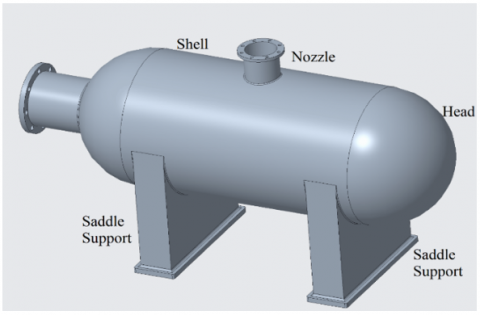
Pressure vessel which is modeled has a shell length of 2234 mm, inner diameter of 1300 mm and a wall thickness of 16 mm. The cylindrical vessel is integrated with hemispherical ends at both ends. Saddle support is designed to provide structural integrity and reduce shocks and vibration on the vessel during operation and the inlet and outlet nozzles support the fluid circulation. The dimensions of the pressure vessel are provided in Table 1. The pressure vessel is modelled using CREO 6.0 and analyzed using ANSYS Workbench 17.0 FEA software. Figure 1 shows the CAD model of pressure vessel.
Table 1. Pressure vessel dimensions
|
Sl. No. |
Description |
Dimension (mm) |
|
1 |
Total length of pressure vessel |
2534 |
|
2 |
Internal diameter of pressure vessel |
1300 |
|
3 |
Pressure vessel wall thickness |
16 |
|
4 |
Inlet nozzle diameter |
530 |
|
5 |
Outlet nozzle diameter |
320 |
Figure 1. CAD model of pressure vessel
Three different materials; stainless steel, carbon steel, and titanium alloy were selected to study the structural performance of the pressure vessel. These materials offer good corrosion resistance, apart from structural rigidity and stiffness required for such high-performance applications. The properties of the chosen materials are listed in Table 2.
Table 2. Properties of materials used in the study
|
Material Properties |
Titanium Alloy |
Stainless Steel |
Carbon Steel |
|
Density (kg/m3) |
4620 |
7750 |
7850 |
|
Modulus of elasticity (MPa) |
96000 |
1.93 x 10⁵ |
2 x 10⁵ |
|
Poisson’s Ratio |
0.36 |
0.31 |
0.295 |
|
Tensile yield strength (MPa) |
930 |
207 |
490 |
|
Ultimate tensile strength (MPa) |
1070 |
586 |
635 |
|
Bulk Modulus (MPa) |
1.14 x 10⁵ |
1.69 x 10⁵ |
1.62 x 10⁵ |
|
Shear Modulus (MPa) |
3.52 x 10⁴ |
7.37 x 10⁴ |
7.72 x 10⁴ |
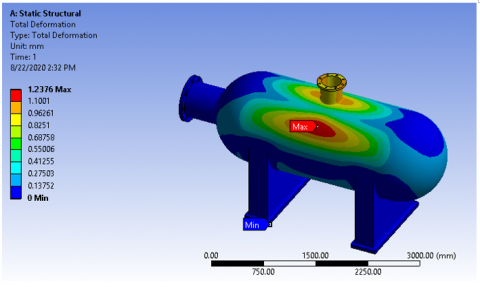
The deformation and stress results for the pressure vessel subjected to different internal pressures have been presented in this section. Figures 2 and 3 show the total deformation and equivalent von-mises stress results respectively for the pressure vessel obtained through ANSYS Workbench. Boundary conditions such as fixed support and internal pressure are applied to the model. The saddle support was fixed at the bottom. The pressure inside the vessel chamber was varied from 2-5 MPa in steps of 1 MPa.
Figure 2. Total deformation in pressure vessel subjected to internal pressure
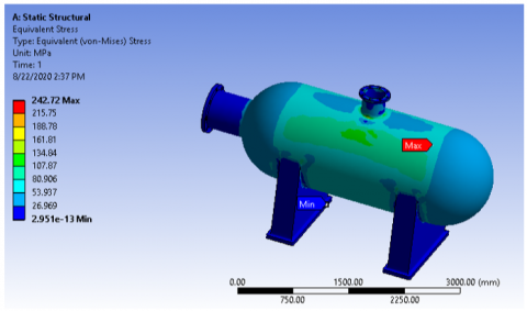
Figure 3. Equivalent stress in pressure vessel subjected to internal pressure
From Figures 2 and 3 shows the distribution of the deformation and stress in the vessel can be observed. It is observed that maximum deformation is at the circumference of the cylindrical shell. The maximum equivalent stress is at the adjoining portion of the cylindrical shell and the hemispherical head section. Due the circumferential pressure, the stress concentration zone is located in this region. For the varying internal pressure values, the output parameters such as deformation, stress and strain for the three chosen materials are tabulated in Tables 3, 4, and 5 respectively.
Table 3. FEA deformation results for different materials
|
Sl. No. |
Pressure (MPa) |
Deformation (mm) |
||
|
Titanium alloy |
Stainless Steel |
Carbon Steel |
||
|
1 |
2 |
2.51 |
1.27 |
1.23 |
|
2 |
3 |
3.76 |
1.91 |
1.85 |
|
3 |
4 |
5.02 |
2.55 |
2.47 |
|
4 |
5 |
6.27 |
3.18 |
3.09 |
Table 4. FEA stress results for different materials
|
Sl. No. |
Pressure (MPa) |
Stress (MPa) |
||
|
Titanium alloy |
Stainless Steel |
Carbon Steel |
||
|
1 |
2 |
226.33 |
238.49 |
242.72 |
|
2 |
3 |
339.49 |
357.73 |
364.08 |
|
3 |
4 |
452.66 |
476.98 |
485.44 |
|
4 |
5 |
565.82 |
596.22 |
606.80 |
Table 5. FEA strain results for different materials
|
Sl. No. |
Pressure (MPa) |
Strain (mm/mm) |
||
|
Titanium alloy |
Stainless Steel |
Carbon Steel |
||
|
1 |
2 |
0.0026 |
0.0014 |
0.0015 |
|
2 |
3 |
0.0040 |
0.0021 |
0.0022 |
|
3 |
4 |
0.0053 |
0.0028 |
0.0029 |
|
4 |
5 |
0.0067 |
0.0036 |
0.0036 |
Based on the stress values derived from FEA and the experimentally derived tensile strength, Factor of safety (FOS) for the vessel design was calculated and those results are tabulated in Table 6.
Table 6. FOS for the different material pressure vessels
|
Sl. No. |
Pressure (MPa) |
Factor of safety |
||
|
Titanium alloy |
Stainless Steel |
Carbon Steel |
||
|
1 |
2 |
4.10 |
0.86 |
2.01 |
|
2 |
3 |
2.73 |
0.57 |
1.34 |
|
3 |
4 |
2.05 |
0.41 |
1.00 |
|
4 |
5 |
1.64 |
0.34 |
0.80 |
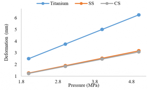
Figure 4. Comparison of deformation for different material pressure vessels
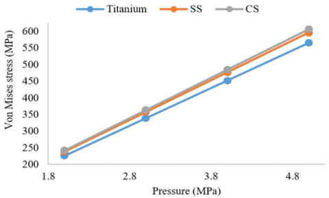
Figure 5. Comparison of stress for different material pressure vessels
Figure 6. Comparison of strain for different material pressure vessels
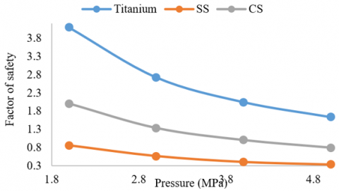
Figure 7. Comparison of FOS for different material pressure vessels
Figures 4, 5 and 6 show the variation of deformation, stress and strain with the pressure. From the graphical representation is evident that there is a linear rise of these three parameters with the increase in the pressure. In the Figure 4 there is high deformation observed for titanium alloy it is because the density of the titanium is less which is half of that of steel. Also, elastic modulus of the titanium is low which makes the metal to flex and deform easily. When yield strength of both steel and titanium are compared, it is found that, steel is stronger. Results indicate that, titanium metal deforms twice that of steel. Stress is given by the magnitude of force on the surface area of the vessel. Figure 5 shows that for the higher pressure, carbon steel material incurs high stress compared with that of titanium. Titanium is 45% lighter to that of steel and strength to weight ratio is higher than that of steel, therefore it can handle high pressure and yield minimum stress. The stress acting on the carbon steel is 7.24% higher than that of steel.
Linear Strain is defined as the ratio of the change in the length to the original length. In pressure vessels, volumetric strain is considered. Figure 6 shows that, the strain observed for the titanium alloy is 86% higher than that of steel for higher internal pressures. The reason being the low density of titanium alloy. FOS is the ratio of the tensile yield stress to the working stress induced in the material. Figure 7 indicates that there is a drop in the FOS with the rise in internal pressure. Lower internal pressure contributes higher FOS for all considered materials and among them, titanium alloy gave the maximum FOS of 4.10. This is due to high specific strength of titanium alloy compared to steel specimens. At lower internal pressures, the value of FOS is higher for titanium by 60% compared with steel. As the pressure increases till the peak value, the difference in percentage FOS remains constant.
In the present study a nozzle is fitted to the pressure vessel and subjected to boundary conditions to carry out stress and failure analyses. The pressure vessel is modelled using CREO 6.0 adhering to corresponding design standards and FEA analysis is performed to derive necessary output. The purpose of this study is to determine reliable and accurate results in the analysis of pressure vessels subjected to structural loads. From the detailed FEA study of the pressure vessels, the following conclusions are drawn.
[1] Khorsand, M., Fu, K., Tang, Y. (2019). Multi-directional functionally graded materials for enhancing the durability of shell structures. International Journal of Pressure Vessels and Piping, 175: 103926. https://doi.org/10.1016/j.ijpvp.2019.103926
[2] Xiao, Z., Shi, J., Cao, X., Xu, Y., Hu, Y. (2018). Failure probability analysis of pressure vessels that contain defects under the coupling of inertial force and internal pressure. International Journal of Pressure Vessels and Piping, 168: 59-65. https://doi.org/10.1016/j.ijpvp.2018.09.005
[3] Patil, A. (2013). Finite element analysis of optimized compound cylinder. Journal of Mechanical Engineering Research, 5(5): 90-96. https://doi.org/10.5897/JMER10.059
[4] Mali, A., Bhosale, H., Bedi, D.S., Modasara, A. (2017). A review paper on study of pressure vessel, design and analysis. International Research Journal of Engineering and Technology, 4(5): 1369-1374.
[5] Jegatheesan, J., Zakaria, Z. (2018). Stress analysis on pressure vessel. Environment and Ecosystem Science, 2(2): 53-57. http://doi.org/10.26480/ees.02.2018.53.57
[6] Bankar, N.B., Swaminadhan, P. (2015). A carbon drain pressure vessel & nozzle stress analysis. International Journal of Engineering Sciences and Research Technology, 4(7): 578-585. https://doi.org/10.5281/zenodo.160903
[7] Gupta, S.R., Vora, C.P. (2014). A review paper on pressure vessel design and analysis. International Journal of Engineering Research and Technology, 3(3): 295-300.
[8] Kharat, A., Kamble, S. (2017). Stress analysis in composite pressure vessels – A review. International Journal of Innovative Research in Science Engineering and Technology, 6(9): 17950-17957. https://doi.org/10.15680/IJIRSET.2017.0609017
[9] Moss, D.R., Basic, M. (2013). Flange Design, Pressure Vessel Design Manual. Elsevier, 139-183.
[10] Praneeth, B., Rao, T.B.S. (2012). Finite element analysis of pressure vessel and piping design. International Journal of Engineering Trends and Technology, 3(5): 567-570.
[11] Hutton, D.V. (2014). Fundamentals of Finite Element Analysis, First Edition. McGraw-Hill Inc, New York.
[12] Ahmed, M., Khan, R.U., Badshah, S., Jan, S. (2014). Finite element investigation of geometry effect on pressure vessel under combined structural and thermal loads. International Journal of Engineering and Advanced Technology, 4(2): 2249-8958.
[13] Pratama, J., Fitriyana, D.F., Siregar, J.P. (2020). A low cost validation method of finite element analysis on a thin walled vertical pressure vessels. Journal of Physics: Conference Series, 1444: 1-17. https://doi.org/10.1088/1742-6596/1444/1/012042
[14] Suranjan, S. Shetty, S., Selvan, C.P. (2015). Estimation of stresses and temperature distribution and their effects in pressure vessel. International Journal of Advances in Engineering Technology, 8(1): 1918-1926.
[15] Dubal, S.V., Gajjal, S.Y. (2015). Finite element analysis of reactor pressure vessel under different loading conditions. International Conference on Computing Communication Control and Automation, pp. 5-11. https://doi.org/10.1109/ICCUBEA.2015.12
[16] Sachidananda, H.K., Prasanth, D. (2019). Design and analysis of pressure vessel. International Journal of Mechanical and Production Engineering Research and Development, 9(5): 125-136. https://doi.org/10.24247/ijmperdoct201912
[17] Niranjana, S.J., Patel, S.V., Dubey, A.K. (2018). Design and analysis of vertical pressure vessel using ASME Code and FEA technique. IOP Conference Series: Material Science and Engineering, 376(1): 012135. https://doi.org/10.1088/1757-899X/376/1/012135
[18] Maleki, M., Farrahi, G.H., Jahromi, B.H., Hosseinian, E. (2010). Residual stress analysis of autofrettaged thick-walled spherical pressure vessel. International Journal of Pressure Vessels and Piping, 87(7): 396-401. https://doi.org/10.1016/j.ijpvp.2010.04.002
[19] Baaji, B., Saraswathamma, K., Madabhushi, R., Sutar, S. (2016). Design and analysis of spherical pressure vessels with pressure and thermal effects. International Journal of Mechanical Engineering and Automation, 3(6): 239-248.
[20] Rustam, R., Nazri, A.F.A., Tasliman, M.R.M., Mahmud, J. (2018). Finite element simulation and analysis for the design of a pressure vessel with expansion joint. International Journal of Materials Mechanics and Manufacturing, 6(4): 268-272. https://doi.org/10.18178/ijmmm.2018.6.4.389