Shubhashree Mohapatra | Hrushikesh Sarangi* | Upendra Kumar Mohanty | Priyanka Rath
OPEN ACCESS
The paper undertakes to demonstrate dispersal of particles with varied densities in a melt solidifying in a rotating mould, through laboratory experiment. Molten wax, wood and sand particles were considered for the purpose. Mixture of the three, in pre decided proportions, was poured into a refractory lined, split mould, rotating about its vertical axis at different speeds and the melt was allowed to solidify under the influence of the resulting centrifugal force. Slices of the casting so obtained, were examined using an optical microscope. Also, temperature and viscosity profiles of the melt, as well as the velocity and position of the particles in the melt at any instant of time, were analyzed, with the aid of relevant mathematical equations. The solidified wax was seen to have heavy sand-particles at the outer most surface and the thickness of the particle- rich-zone decreased with the increase of mould-rotational-speed. The analytical and experimental findings were in good agreement. The investigation, also, established significant contributions of combinations of ‘speed of rotation’ and ‘mould size’ towards graded distribution of particles in the solidified melt leading to gradation of properties in the resultant casting.
dispersal of particles, centrifugal force, viscosity profile, temperature profile, particle-rich-zone, graded properties, analytical findings
Various processing factors control particle distribution in centrifugal castings. Both, the liquid metal and the reinforcement particles experience a centrifugal force acting away from the centre of the rotating mould. The velocity of the particles moving in the melt, as a consequence of the outward-directed centrifugal force, depends on its density. Thus, when other factors remain unchanged, a particle with a higher density is expected to describe longer distances in a given melt as dictated by the relative densities of the melt and the particle and is supposed to reach the inside of the outer surface of the mould wall earlier than a particle of lesser density. However, in the real-life case processing parameters such as mould temperature, cooling rate, viscosity of the melt, solidification rate of the melt etc., play important role and are responsible for particle gradation leading to property gradation in the functionally graded materials (FGMs). For an example, it may be appreciated, particles do not move unopposed in the melt driven by the respective densities alone. With the gradual drop of temperature there is a gradual increase in the viscosity of the melt offering greater resistant to the moment of the particles and restricting its motion [1] in the melt. On the basis of the above, it can be said with emphasis the functional gradation of a material can be preconceived and obtained by monitoring and controlling various processing factors pertaining to centrifugal casting processes resulting in a desired graded distribution of the particles involved.
FGMs refer to the group of materials possessing a gradual change of composition across the cross section in certain specific direction, imparting multifunctional behaviour to a single component [2]. The gradual change of composition in these materials is brought about by adopting fabrication methods capable of developing a continuous (smooth) gradual distribution of the second phase/externally added/insoluble/suspended particles in a suitable matrix material [3]. Thus, the gradation of functions in these materials is a consequence of smooth, gradual distribution of these particles in the matrix. A continuous gradient of composition in the FGMs can be obtained by adopting several processes such as thermal spraying, sol-gel process, liquid infiltration, spray-forming, powder metallurgy, vapour deposition etc. [4-7]. However, over the edges, the centrifugal casting process has proved to be a cost effective, simple process for fabricating FGMs. Indeed, several investigators [8-19] have adopted this method involving a rotating mould for casting of FGMs.
The design and fabrication of several functionally graded metal matrix composites (FGMMCs), important engineering materials, best suited for the production of multi functional components with pre-conceived contradictory properties, throws a challenge to the modern-day engineer. A suitable material for production of a gear provides a good example of property distribution in materials. In a gear the surface must be hard a wear-resistant, where as the material must have high toughness in the interior keeping in mind the dynamic load to which the gear ought to be exposed to during its service life [20]. In the case of AMCs (Aluminium matrix composites), suitable for fabricating brake rotors and cylinders, piston, connecting rod, etc., it is reported uniformly distributed particles adversely affect the ductility and fracture-toughness properties [21]. However, these lost properties can be regained by a non-uniform graded distribution of the particles in the aluminium matrix creating a particle-rich and particle-devoid region in the resultant functionally graded composite casting. Such a situation, it is claimed [22], wood reduce the crack driving force by increasing the resistance of the material to crack initiation and growth. Many processing factors related to the melt and to the mould, such as mould rotational speed, melt temperature, mould dimensions, cooling provisions, etc., can be controlled and monitored for the production of FGM in the centrifugal casting route, effectively tailoring the graded distribution responsible for graded properties in the casting keeping its end use in mind. Examples can be cited in this respect [23-27] pertaining to the graded distribution of Mg2Si particles in an aluminium matrix. The less dense hard Mg2Si particles as reinforcement in the Al-Mg2Si composite get segregated in the bore region of the casting i.e., the inner surface of the mould wall resulting in development of better wear-properties to the inner periphery of the casting. Similarly, investigators have exploited the advantage of centrifugal casting methods for developing better wear properties on the outer surface of castings by using particles with higher densities than the aluminium matrix and making these hard reinforcement particles to get segregated on the outer surface of the casting [28-31]. Below the surface the concentration of the particles reduced gradually resulting in a graded property distribution from hard, wear resistant outside surface to strong and ductile interior regions in the casting.
The present investigation does not deal with the microstructural development in the casting but focuses on macro segregation of the particles in the casting formed in rotating moulds as influenced by different parameters for facilitating the production of FGMs, suitable for specific end uses. Wax, free flowing at 130 °C, crystalline in nature, solidifying with graded increase of viscosity when the temperature is lowered has been adopted as the simulating medium. Molten wax embedded with sand and wood particles having distinct, different densities, is allowed to solidify in a rotating mould. The simultaneous segregation of denser sand and lighter wood particles in the solidifying wax melt has been examined through an optical microscope. The pattern and order of segregation of these particles have been analysed with the aid of derived equation in terms of standard mathematical expressions pertaining to the velocities of the particle in the melt, the temperature and the viscosity profile in the melt and the volume fraction of the particles in the melt at different location at any instant of time. Also, thicknesses of particle rich zone as a function of the speed of the rotation of the mould are obtained and analysed. These analysed, predicted data are compared with experimental observations for the shake of validation.
2.1 Experimental setup
The photograph of the setup used for experimentation in the present investigations is presented in Figure 1, detailing all the constituent components. A mild steel, split mould, lined with magnesite ramming mass and set on its vertical axis is used for casting purposes. The vertical mould is bolted coaxially to a base plate, rotating about its vertical axis through a pair of ball bearings. The base plate is coupled with the shaft of a rotor by belt-pulley arrangement and rotates about its vertical axis powered by the motor. The rotational speed of the mould, varied by regulating the supply voltage through variac to the motor, is recorded using stroboscope.
Figure 1. Centrifugal casting apparatus (photograph)
2.2 Material used for experimentation
Molten wax was adopted as the simulation medium. It was impregnated with wood and sand particles as the segregating reinforcement particles. The detailed specifications of these materials are provided in Table 1. The surface of the wood-particles is painted for the shake of identification. As the wood particles have the tendency to soak the moisture or hot molten wax during pouring, its density will tend to increase compare to the over dry density. For the mathematical calculation, the density of the wood dust particle at its fully moisture content state, i,e., green density calculation is done and the values are given in Table 1.
Table 1. Physical property of the matrix and reinforcement
|
Physical properties |
Paraffin wax |
Sand |
Wood dust |
|
Density of the material (ρ) (kg/m3) |
737 (135 °C) |
1600 |
358 oven dry 892 green strength density* |
Note: * Green density of wood = mass of the wet wood particles/ volume of particles
2.3 Procedural details of experiment
Paraffin wax was melted in an electric oven at 130 °C. Sand (0.109 volume fraction) and wood (0.110 volume fraction) particles were introduced to the molten wax with stirring of the melt for the uniform mixing purpose.
The mould was rotated at a speed of 50 rpm. The molten wax-wood-sand mix is poured into the rotating mould gradually. Once the pouring was completed, the speed of rotation of the mould is increased to the pre decided level by adjusting the variac. The rotation continued for the casting at the pre decided speeds till the respective casting solidified.
The mould is now split into its two halves and the casting was retrieved. The mould was again at with fresh refractory lining in place for the casting at another pre decided rotational speed.
Using a hot steel wire, slices of the solidified casting are cut along its length for the examination. Micro-graphs are taken using an optical microscope. The thickness of the particle rich zones pertaining to both wood and sand particles is measured and recorded.
2.4 Analysis and predictions of particle distribution
The basic equation of forces acting on a moving particle in a solidifying melt in a rotating mould, under the influence of centrifugal forces in a liquid is given below [32].
${{F}_{net}}={{F}_{R}}+{{F}_{G}}+{{F}_{S}}+{{F}_{C}}+{{F}_{B}}$ (1)
where,
Fnet= Net force on the particle, N
FR = Centrifugal force, N
FG = Gravitational force, N
FS= Drag force, N
FC= Coriolis force, N
FB= Buoyant force, N
In equation (1), FG is negligible due to low values of the gravitational acceleration (g) in comparison to ω2r, the centrifugal acceleration and is neglected. Also FC, the coriolis force responsible for vertical displacement of the particle is a negligible quantity for small particle and is neglected in the final expression for the net force. Thus, equation (1) reduces to the following form
${{F}_{net}}={{F}_{R}}+{{F}_{S}}+{{F}_{B}}$ (2)
Considering equilibrium of the particles in the melt, the net force Fnet, acting on the particle can be considered to be zero. This leads to the expression
${{F}_{R}}+{{F}_{S}}+{{F}_{B}}=0$ (3)
In terms of the various melt and reinforcement (particle) factors FR=VSω2rρp; FS=6πµrpvp; FB=VSω2rρl. Also as both, the drag force FS and buoyant force FB tends to oppose the transport of the particles in the melt, they are considered to be negative quantities. Now equation (3) can be rewritten as
${{V}_{S}}{{\omega }^{2}}r{{\rho }_{p}}-6\pi \mu {{r}_{p}}{{v}_{p}}-{{V}_{S}}{{\rho }_{l}}{{\omega }^{2}}r=0$ (4)
where,
ω = Angular velocity, (1/s)
r = Centrifugal radius, (m)
ρp = Density of particle, (kg/m3)
ρl = Density of liquid, (kg/m3)
µ = Viscosity of the melt, (Pas)
rp = Radius of the particle, (m)
vp = Velocity of the particle, (m/sec)
vs = Volume of the solid, (m3)
Equation (4) is used to find an expression for the velocity of the moving particles in the molten wax using which the velocity of the wood and sand particles can be calculated by incorporation of the available data.
2.5 Velocity of the particle in the wax melt
The expression derived for vp, the velocity of the particle in melt under the influence of the net force using equation (4), can be given as under (Appendix A)
${{v}_{p}}=\frac{4{{r}_{p}}^{2}{{\omega }^{2}}r({{\rho }_{p}}-{{\rho }_{l}})}{18{{\mu }_{{}}}}$ (5)
Now, putting specific values of the various terms in equation (5), the velocity of the wood and sand particles are computed to be 0.00797 m/sec and 0.177m/sec respectively. (Appendix B)
2.6 Time taken by the particles to reach the mould wall
Using the respective estimated velocities, the time taken by the wood and the sand particles to reach the mould wall is found out to be 14.51 s and 0.1629 s respectively, travelling a radial distance of 29 mm each (mould dia= 58mm) (Appendix C).
2.7 Temperature and viscosity profiles of the melt
Temperature variations in the melt with lapse of time is estimated using Newton’s law of cooling. Accordingly
$T(t)={{T}_{a}}+({{T}_{0}}-{{T}_{a}}){{e}^{-kt}}$ (6)
T(t) = Temperature at time, t, (K)
Ta = Ambient temperature, (K)
T0 = Initial temperature, (K)
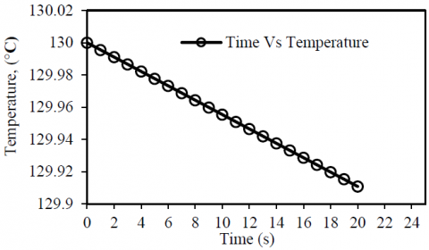
Using equation (6), the temperature drop in the melt is found to be 0.001 °C and 0.065 °C respectively during the travel of the sand and wood particles in the melt (Appendix D). The initial temperature of the melt being the pouring temperature (130 °C), the drop in the temperature Vs time, i.e., the temperature profile of the melt, is presented in Figure 2, during the transport of the particles.
Figure 2. Temperature drop with change in time
Similarly profiles of the viscosity vs temperature of the melt during the travel of the particles, for the respective temperature drop is estimated (Appendix E) and presented in Figure 3, using Arhenious equation.
$\mu =A\exp \left( \frac{Q}{R.T} \right)$ (7)
where, ‘A’ is a constant, ‘Q’ is the activation energy of the matrix in KJ/mol, ‘R’ is the universal gas constant (8.31441 J/(mol·K)), ‘T’ is the absolute matrix temperature (K) and ‘µ’ is the viscosity of the melt, (Pas).
Figure 3. Viscosity change at change in temperature
From the temperature and the viscosity profiles, it is seen that there is a minimal increase in the viscosity of the melt during the travel of the particles with a very small drop in the melt temperature.
2.8 Volume fraction and particle distribution pattern
Volume fraction of the respective particles at a specific location in the melt is defined as the ratio of the volume of the solid particles in that location to the total volume of the particles in the melt. It continuously changes due to the transport of the particle in the melt.
For estimating the volume fraction at any location in the melt, at any instance, the following equation are made use of [28]
For $\rho_{p}>\rho_{1}$ $V_{f s}(t+\Delta t)=\frac{V_{s}}{\pi\left(r_{i+1}^{2}(t+\Delta t)-r_{i}^{2}(t+\Delta t)\right)}$ (8)
For $\rho_{1}>\rho_{p}$ $V_{f s}(t+\Delta t)=\frac{V_{s}}{\pi\left(r_{i}^{2}(t+\Delta t)-r_{i-1}^{2}(t+\Delta t)\right)}$ (9)
$V_{f s}(t+\Delta t)=$ Volume fraction at time, $t+\Delta t$
$t=$ time, $(\text { sec })$
$\Delta t=$ time step, (sec)
$r_{i}(t+\Delta t)=$ Position of the particle in i th section at time $t+\Delta t(\mathrm{m})$
The volume fraction estimations are carried out using Microsoft Excel based on the principle of conservation of total mass at different locations as a function of the distance from the inner surface of the mould wall using a time step ( $\Delta t$) of 0.005 seconds for the sake of accuracy. Also the estimation of volume fraction made use of the terms r(t), the position of a particle at any instant, µeff, the effective viscosity of the melt as influenced by the volume fraction itself and the change in density of the melt with time. The expressions for these equations are given below
$r(t)={{r}_{0}}\exp \left[ \frac{4{{\omega }^{2}}({{\rho }_{p}}-{{\rho }_{l}}){{r}_{p}}^{2}t}{18{{\mu }_{eff}}} \right]$ (10)
where, r0 = Radius of the particle at time t = 0, (m)
Equation (10) is derived from equation (5) (Appendix F) and is valid when the following condition is met [33].
${{r}_{p}}\le {{r}_{pc}}={{\left( \frac{9{{\mu }^{2}}}{4\vartriangle \rho {{\omega }^{2}}r{{\rho }_{l}}} \right)}^{\frac{1}{3}}}$ (11)
where, rpc = Critical radius of the particle, (m)
${{\mu }_{eff}}=\mu [1+2.5{{V}_{f}}(t)+10.05{{V}_{f}}^{2}(t)] $ (12)
where, Vf(t) = Volume fraction at time, t
Change in density is presented by
${{\rho }_{i+1}}=\frac{{{\rho }_{i}}}{1+\beta ({{T}_{i+1}}-{{T}_{i}})}$ (13)
where, β is the expansion coefficient and (Ti+1-Ti) is the temperature difference.
The Microsoft Excel charts generated are presented in Figure 4 and Figure 5. The figures depict the variation in the thickness of the particle rich zone pertaining to both the wood and sand particles, with rotational speed of the mould, this thickness of the particle rich zone representing the particle distribution pattern in the melt. For the heavier sand particles, the volume fraction very close to the mould wall is same as its original value in the melt. With the increase of the speed of the rotation of the mould the thickness of the particle segregation layer decreases. Also at relatively lower speeds of rotation the thickness of the particle rich zone assumes higher values, not being able to describe higher radial distances in the melt, restricting their locations to regions relatively away from the mould wall. For the relatively less dense wood particles, however, the initial layer of segregation starts from the region where the volume fraction of sand is zero, i.e, on the inner surface of the segregated sand particles and is reached away from the mould wall.
Figure 4. Variation of volume fraction of sand particles from the outer casting face
Figure 5. Variation of volume fraction of wood dust particles from the reference casting radius
2.9 Experimental results
The slices of the solidified wax (Figure 6) is examined under the optical microscope. The order of segregation of the particle is ascertained and the variations of thickness of the particle rich zone with speed of rotation of the mould is measured. These readings, both predicted and observed, are housed in Table 2.
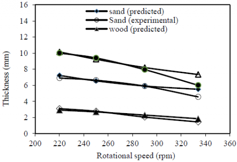
The table clearly establishes that quantitatively both the predicted and observed data are in good agreement. Qualitatively, the table shows a decrease in the thickness of the particle rich zone with the increase in the speed of the rotation of the mould. For the ready reference of the reader, the data presented in Table 2 are also presented graphically in Figure 7.
It is also observed that the sand particles segregated on the inner surface of the mould wall followed by the wood particles. This is in line with the predictions based on the particle velocity as estimated for the two types of the particles. Under the given conditions the radial velocities of the sand particles (0.177 m/sec) is more than that of the wood particles (0.00797 m/sec). Obviously, sand particles formed the outer most layer in the solidified wax.
From the above, it can be inferred with considerable justification, the predicted results based on analysis are validated both qualitatively and quantitatively by the experimental observations.
Figure 6. Slices of castings produced in centrifugal casting route showing decrease in thickness of the particle segregated zone
Table 2. Variation of the thickness of particle rich layer with rpm
|
Rota-tional speed, rpm |
Thickness of sand rich zone, mm |
Thickness of wood dust segregated zone, mm |
Total thickness of particle rich zone, mm |
|||
|
Pre-dicted |
Expe-riment |
Pre-dicted |
Expe-riment |
Pre-dicted |
Expe-riment |
|
|
220 |
7.23 |
6.9 |
2.92 |
3.10 |
10.15 |
10.00 |
|
250 |
6.55 |
6.63 |
2.689 |
2.77 |
9.24 |
9.40 |
|
290 |
5.91 |
5.9 |
2.3 |
2.05 |
8.21 |
7.95 |
|
334 |
5.5 |
4.56 |
1.843 |
1.44 |
7.34 |
6.00 |
Figure 7. Thickness of the particle rich region for sand and wood dust particles at different rotational speeds
In the present work molten wax mixed with given proportion of denser sand and lighter wood particles, is considered as the simulation medium for the study of particle distribution in a melt solidifying in a rotating mould. Use of the simulation mediums to study the behaviour of real metallic alloys through laboratory experiments is already in place [34]. In particular, the present work draws a parallel from the work reported by Gao et al. [35]. The authors developed a one dimensional numerical solidification model, taking into account, the transport of particles in the molten matrix, to predict the temperature and volume fraction distribution. The model could be validated under simulated laboratory conditions using pure liquid water as the matrix phase and glass beads as the particle phase solidifying in a rectangular mould under gravity. Finally, the validated model could be used for the simulation of metal matrix ceramic system (Al/SiC) to weigh the effects of different processing factors in the production of FGMs in the centrifugal casting route. Economy and convenience constitute the two major purposes of using such non metallic materials as simulation mediums to predict the behaviour of real life case. These materials may include plasticine, paraffin wax, clay and mixtures of these materials. The study avoids the adoption of normal production run and ensures a much cheaper, easy to process material as compared to a prototype material such as alloys. Such small scale experiments using plasticine as the modelling materials for predicting the patterns of metal flow in various metal forming processes like extrusion [36], hot forging of steel [37], rolling [38] and rotary forging [39] etc., have been reported by several experimenters. The simulation process is carried out based on the simulation of real life case using an appropriate simulation medium and tools under conditions in which the real life case is implemented.
In the instant case, for simulation purposes, a vertical split mould with a refractory lining in place, rotating at different speeds with the aid of a motor and variac combination, is adopted as the forming tool. Molten wax is used as the simulation medium and mixed with wood and sand particles with different densities. Wax is selected since it is crystalline, rendering a much higher degree of structural homogeneity to the material as in the case of a metallic alloy. It may be appreciated, depending on these characteristics, wax has been utilised as the simulation medium by several researchers [40-42] for prediction of the flow pattern of metals pertaining to various metal forming processes. The practice for teaching the flow of metals to the undergraduate students is also in place as detailed by Button [43].
On the basis of the above, it can be argued with simple justification, the present method of experimentation adopting wax impregnated with sand and wood particles as the simulation medium, to predict the situation in a real life case pertaining to real metallic alloys, is not out of place.
Using standard equations, expressions for the velocity of transport of wood and sand particles in a wax melt solidifying in a rotating mould are derived. Velocity of transport of the particles in the melt and the time taken for the particles to reach the mould wall are calculated. On the basis of the above, the temperature and the viscosity profiles of the melt are established. The volume fraction distribution of particles in the melt are found out on the basis of the position of the particle in the melt at any instant of time.
Adopting molten wax mixed with wood and sand particles as the simulation medium, experimentation is conducted under laboratory simulated conditions to study the distribution of the particles in the wax melt solidifying in a rotating mould.
It is found that sand particles occupy the outer most layers in the solidified wax followed by the wood particles. This is in agreement with the calculated values of the velocities of the respective particles in the wax melt, as the heavier sand particles with a higher velocity of 0.177 m/sec compared to that of 0.008 m/sec for the lighter wood particles, described a higher radial distance through the melt. Also, analytical results reveal a decrease in the thickness of the particle rich zones of both types of particles with an increase of the speed of the rotation of the mould. Measurement through optical microscope examinations of the cross section of the solidified wax confirmed the same. It is observed that the thickness of the particle rich zone in the castings at different speeds of rotation of the mould, are in close agreement with the same obtained through analysis with the aid of the related mathematical expressions. Thus, the findings of analysis, with the aid of standard mathematical expressions are validated by laboratory experimentation using a simulating non-metallic medium.
It is interesting to note that the experimental as well as the analytical findings established the formation of a particle rich zone on the inner surface of the mould wall which got more and more compact with increase in rotational speed of the mould. Microscopic examination of the slices of the castings produced at different speeds of rotation of the mould (Figure 6) revealed particle clustering at the respective regions of segregation of the wood and sand particles. This could be a result of collision between the particles aided by the low viscosity of the melt, under similar lines as explained by Pines et al. [44]. However, such clustering of the particles is an unwanted and unfavourable situations for the real life case since the agglomeration of the particles are most likely to form porosities in the casting in the respective regions [45]. Further, similar particles with similar densities got clustered at the respective regions as stated above and a concentration gradient of the particles i.e., a graded distribution of the particles was not witnessed. This may be attributed to the adoption of inappropriate ‘mould dimension’ and ‘speed of rotation’ combination during experimentation. The time taken even at the lowest speed of the rotation of the mould by the particles to reach the mould wall inside surface is very small (0.16 s for sand and 14.51 s for wood particle), generating an almost flat temperature and viscosity gradient in the melt (Figure 2 and Figure 3). This low rise in the viscosity due to insignificant fall in temperature is seen to result in an unopposed movement of the particles in the melt till they reached the mould wall and an interplay between the freezing front propagation and particle movement responsible for a graded distribution of the particles is not witnessed. It is also interesting to note [46] that segregation of second phase/ rejected solids in any section of the casting is dictated by the speed of movement of the two solidification fronts in the said section in the casting. One of the fronts moves inwards from the mould periphery to the inner zones of the casting due to heat conduction through the mould wall to the ambiance and the other one in opposite direction, due to heat losses on account of forced convection and radiation. The intersection of the two fronts decides the location of micro segregation of the suspended crystals or the insoluble phases. For instance, if the speed of the travel of the inner to the outer moving front is higher than the other moving front, segregation occurs at relatively outer planes and vice versa. Also if the speed of movement of both the fronts is equal, maximum macro segregation occurs at the mid-thickness of the section bringing in a graded distribution of the particles.
In the present case, however, before any of the solid fronts could come to being, the particles reached the mould periphery dictated by the respective densities under the influence of the relatively high rotational speed of the mould and the resultant temperature and viscosity profiles of the melt. This resulted in the formation of the particle rich zone for the heavy sand particles on the outermost regions of the casting closely followed by that of the lighter wood particles. Such a situation does not promote the graded distribution of the reinforcement particles in the casting and is detrimental to the prospects of the production of FGMs. In view of the above, it is only pertinent that rpm of the mould is decided keeping an eye to the mould dimensions for the setting up of a desired temperature gradient and viscosity profile in the melt for a graded distribution of the reinforcement phase for gradation of mechanical properties across the cross section of the casting.
(1) The analytical results concerning the position of the particles and thickness of the respective particle segregated layers are validated through experimental findings.
(2) Density of the particles in a melt, solidifying in a rotating mould, decide the order of segregation of the particles, the particles with the highest density occupying the outermost layer in the casting.
(3) Volume fraction distribution of the particles in the melt strongly depend on the rotational speed of the mould.
(4) Factors like gradual changes in melt viscosity, temperature profile, and rate of solidification of the melt in conjunction with the speed of rotation of the mould decide the gradient of distribution of the particles in a melt solidifying in rotating mould.
(5) It is important to operate at an appropriate combination of ‘mould dimensions’ and ‘speed of rotation’ in order to generate a pre-conceived concentration gradient of particles in the melt for the production of FGMs with graded properties across its cross section. In other words, for a graded distribution of the reinforcement phase in the casting, speed of rotation of the mould must be judiciously selected keeping an eye on the size of the casting produced and to avoid particle clustering which may lead to porosities in the particle-rich-regions.
(6) It is recommended that, further studies concerning variations of rate of cooling and the resultant structural variations may be undertaken by the researchers.
Appendix A: Expression for velocity of the particle in the wax melt
$\begin{align} & {{V}_{S}}{{\omega }^{2}}r{{\rho }_{p}}-6\pi \mu {{r}_{p}}{{v}_{p}}-{{V}_{S}}{{\rho }_{l}}{{\omega }^{2}}r=0 \\ & {{\omega }^{2}}r({{\rho }_{p}}-{{\rho }_{l}})-\frac{6\pi \mu {{r}_{p}}{{v}_{p}}}{{{V}_{S}}}=0 \\ & {{\omega }^{2}}r({{\rho }_{p}}-{{\rho }_{l}})=\frac{6\pi \mu {{r}_{p}}{{v}_{p}}}{\frac{4}{3}\pi {{r}_{p}}^{3}} \\ & {{v}_{p}}=\frac{4{{r}_{p}}^{2}{{\omega }^{2}}r({{\rho }_{p}}-{{\rho }_{l}})}{18\mu } \\\end{align}$
Appendix B: Calculation of velocity of reinforcement particle at 220 rpm at a mould radial distance of 29mm
${{v}_{p}}=\frac{4{{r}_{p}}^{2}{{\omega }^{2}}r({{\rho }_{p}}-{{\rho }_{l}})}{18{{\mu }_{{}}}}$
${{v}_{p(sand)}}=\frac{4\times {{(0.4\times {{10}^{-3}})}^{2}}\times {{23.038}^{2}}\times {{(29\times {{10}^{-3}})}^{2}}\times (1600-737)}{18\times 2.66\times {{10}^{-3}}}=0.177m/\sec $
${{v}_{p(wood)}}=\frac{4\times {{(0.1\times {{10}^{-3}})}^{2}}\times {{23.038}^{2}}\times {{(29\times {{10}^{-3}})}^{2}}\times (892-737)}{18\times 2.66\times {{10}^{-3}}}=0.00199m/\sec $
where,
${{r}_{p}}=0.4\times {{10}^{-3}}m$ for sand particles
${{r}_{p}}=0.1\times {{10}^{-3}}m$ for wood particles
$\begin{align} & \omega =23.03rad/\sec \\ & r=0.029m \\ & {{\rho }_{p(wood)}}=892kg/{{m}^{3}} \\ & {{\rho }_{p(sand)}}=1600kg/{{m}^{3}} \\\end{align}$
$\begin{align} & {{\rho }_{l}}=737kg/{{m}^{3}} \\ & \mu =2.66\times {{10}^{-3}}Pas \\\end{align}$ at 130 °C
Appendix C: Estimation of time taken by the particle to reach the mould wall
${{v}_{p}}=\frac{4{{r}_{p}}^{2}{{\omega }^{2}}r({{\rho }_{p}}-{{\rho }_{l}})}{18{{\mu }_{{}}}}$
$\begin{align} & \frac{dr}{dt}=\frac{4{{r}_{p}}^{2}{{\omega }^{2}}r({{\rho }_{p}}-{{\rho }_{l}})}{18\mu } \\ & \frac{r-{{r}_{0}}}{t-{{t}_{0}}}=\frac{4{{r}_{p}}^{2}{{\omega }^{2}}r({{\rho }_{p}}-{{\rho }_{l}})}{18\mu } \\\end{align}$
At t=0 and r0=0.1×10⁻³ m
$t=\frac{(r-0.1\times {{10}^{-3}})\times 18\mu }{4{{r}_{p}}^{2}{{\omega }^{2}}r({{\rho }_{p}}-{{\rho }_{l}})}$
For sand particles
${{t}_{sand}}=\frac{(0.029-0.1\times {{10}^{-3}})\times 18\times 2.66\times {{10}^{-3}}}{4\times {{(0.4\times {{10}^{-3}})}^{2}}\times {{23.038}^{2}}\times {{(29\times {{10}^{-3}})}^{2}}\times (1600-737)}=0.1629\operatorname{s}$
For wood particles
${{t}_{sand}}=\frac{(0.029-0.1\times {{10}^{-3}})\times 18\times 2.66\times {{10}^{-3}}}{4\times {{(0.1\times {{10}^{-3}})}^{2}}\times {{23.038}^{2}}\times {{(29\times {{10}^{-3}})}^{2}}\times (892-737)}=14.51\operatorname{s}$
Appendix D: Temperature of the melt at the particular time taken by particles to reach the mould wall
$T(t)={{T}_{a}}+({{T}_{0}}-{{T}_{a}}){{e}^{-kt}}$
For sand particles
$T(0.1629)=20+110{{e}^{-4.054\times {{10}^{-5}}\times 0.1629}}={{129.999}^{\circ }}C$
For wood particles
$T(014.51)=20+110{{e}^{-4.054\times {{10}^{-5}}\times 14.51}}={{129.935}^{\circ }}C$
Appendix E: Viscosity of the melt at a particular time taken by the particles to reach the mould wall
$\mu =A\exp \left( \frac{Q}{R.T} \right)$
For sand particles
$\mu (0.163)=1.0973\times {{10}^{-5}}\exp \left( \frac{17519.36}{8.31441\times 402.99} \right)=2.04698\times {{10}^{-3}}Pas$
For wood particles
$\mu (14.51)=1.0973\times {{10}^{-5}}\exp \left( \frac{17519.36}{8.31441\times 402.935} \right)=2.04844\times {{10}^{-3}}Pas$
Appendix F: Expression to find out the position of particle at a particular time period
$\begin{align} & {{v}_{p}}=\frac{4{{r}_{p}}^{2}{{\omega }^{2}}r({{\rho }_{p}}-{{\rho }_{l}})}{18\mu } \\ & \frac{dr}{dt}=\frac{4{{r}_{p}}^{2}{{\omega }^{2}}r({{\rho }_{p}}-{{\rho }_{l}})}{18\mu } \\\end{align}$
$\begin{align} & dr=\frac{4{{r}_{p}}^{2}{{\omega }^{2}}r({{\rho }_{p}}-{{\rho }_{l}})}{18\mu }dt \\ & \int\limits_{r0}^{r(t)}{\frac{1}{r}dr}=\int\limits_{0}^{t}{\frac{4{{r}_{p}}^{2}{{\omega }^{2}}({{\rho }_{p}}-{{\rho }_{l}})}{18\mu }}tdt \\ & \ln (r(t))-\ln (r(0))=\frac{4{{r}_{p}}^{2}{{\omega }^{2}}t({{\rho }_{p}}-{{\rho }_{l}})}{18\mu } \\ & \\\end{align}$
${{e}^{\ln (r(t))}}={{e}^{\left[ \ln (r(0))+\frac{4{{r}_{p}}^{2}{{\omega }^{2}}t({{\rho }_{p}}-{{\rho }_{l}})}{18\mu } \right]}}$
$r(t)={{r}_{0}}\exp \left[ \frac{4{{r}_{p}}^{2}{{\omega }^{2}}r({{\rho }_{p}}-{{\rho }_{l}})}{18\mu } \right]$
[1] Zhang, J., Fan, Z., Wang, Y., Zhou, B. (2000). Hypereutectic aluminum alloy tubes with graded distribution of Mg Si particles prepared by centrifugal casting. Materials and Design, 21(3): 149-153. https://doi.org/10.1016/S0261-3069(99)00100-4
[2] Radhika, N., Raghu, R. (2017). Effect of centrifugal speed in abrasive wear behavior of Al-Si5Cu3/SiC functionally graded composite fabricated by centrifugal casting. Transactions of the Indian Institute of Metals, 71(3): 715-726. https://doi.org/10.1007/s12666-017-1204-9
[3] Prabhu, T.R. (2017). Processing and properties evaluation of functionally continuous graded 7075 Al alloy/SiC composites. Archives of Civil and Mechanical Engineering, 17(1): 20-31. https://doi.org/10.1016/j.acme.2016.08.004
[4] Watanabe, Y., Inaguma, Y., Sato, H., Miura-Fujiwara, E. (2009). A novel fabrication method for functionally graded materials under centrifugal force: The centrifugal mixed-powder method. Materials, 2(4): 2510-2525. https://doi.org/10.3390/ma2042510
[5] Hutmacher, D.W., Sittinger, M., Risbud, M.V. (2004). Scaffold-based tissue engineering: rationale for computer-aided design and solid freeform fabrication systems. Trends Biotechnol, 22(7): 354-362. https://doi.org/10.1016/j.tibtech.2004.05.005
[6] Watanabe, Y., Sato, H. (2011). Review fabrication of functionally graded materials under a centrifugal force. Nanocomposites with Unique Properties and Applications in Medicine and Industry, 134-150. https://doi.org/10.5772/20988
[7] Kieback, B., Neubrand, A., Riedel, H. (2003). Processing techniques for functionally graded materials. Materials Science and Engineering: A, 362(1-2): 81-106. https://doi.org/10.1016/S0921-5093(03)00578-1
[8] Rodriguez-Castro, R. (2000). Processing, microstructure and mechanics of functionally graded Al A359/SiCp composite. Ph.D. dissertation. State University of New York at Buffalo, USA.
[9] Rajan, T.P.D., Pillai, R.M., Pai, B.C. (2008). Centrifugal casting of functionally graded aluminium matrix composite components. International Journal of Cast Metals Research, 21(1-4): 214-218. https://doi.org/10.1179/136404608X361972
[10] Wang, K., Jiang, T., Huang, Z., Xue, H., Yang, D., Zhu, Z. (2016). Mechanical and thermal expansion properties of SiCp/ZAlSi9Mg composites produced by centrifugal casting. Journal of Wuhan University of Technology (Materials Science Edition), 31(1): 197-203. https://doi.org/10.1007/s11595-016-1352-5
[11] Prabhu, T.R. (2017). Processing and properties evaluation of functionally continuous graded 7075 Al alloy/SiC composites. Archives of Civil and Mechanical Engineering, 17(1): 20-31. https://doi.org/10.1016/j.acme.2016.08.004
[12] Poornesh M., Harish N., Aithal, K. (2016). Mechanical and tribological properties of centrifugally cast Al-Si-SiC composites. American Journal of Materials Science, 6(4A): 31-35. https://doi.org/10.5923/c.materials.201601.06
[13] Savaş, Ö., Kayıkcı, R., Fiçici, F., Çolak, M., Deniz, G., Varol, F. (2016). Production of functionally graded SiC/Al-Cu-Mg composite by centrifugal casting. Science and Engineering of Composite Materials, 23(2). https://doi.org/10.1515/secm-2014-0141
[14] Qin, X.H., Han, W.X., Fan, C.G., Rong, I.J., Li, Y.Y. (2002). Research on distribution of SiC particles in aluminium-alloy matrix functionally graded composite tube manufactured by centrifugal casting. Journal of Materials Science Letters, 21(8): 665-667. https://doi.org/10.1023/A:1015612726707
[15] Vieira, A., Sequeira, P., Gomes, J., Rocha, L. (2009). Dry sliding wear of Al alloy/SiCp functionally graded composites: Influence of processing conditions. Wear, 267(1-4): 585-592. https://doi.org/10.1016/j.wear.2009.01.041
[16] Vikas, R.S., Maiya, M.U., Jayakumar, E., Rajan, T.P.D., Nagaraja, P.B.C. (2014). Processing and characterization of SiCp reinforced functionally graded AA 6061 aluminium metal matrix composites. International Journal of Advancements in Mechanical and Aeronautical Engineering, 1(2): 61-65.
[17] Jayakumar, E., Jacob, J.C., Rajan, T., Joseph, M., Pai, B. (2016). Processing and characterization of functionally graded aluminum (A319)-SiCp metallic composites by centrifugal casting technique. Metallurgical and Materials Transactions A, 47(8): 4306-4315. https://doi.org/10.1007/s11661-016-3558-8
[18] El-Galy, I.M., Ahmed, M.H., Bassiouny, B.I. (2017). Characterization of functionally graded Al-SiCp metal matrix composites manufactured by centrifugal casting. Alexandria Engineering Journal, 56(4): 371-381. https://doi.org/10.1016/j.aej.2017.03.009
[19] Rajan, T.P.D., Pillai, R.M., Pai, B.C. (2010). Characterization of centrifugal cast functionally graded Aluminum-silicon carbide metal matrix composites. Materials Characterization, 61(10): 923-928. https://doi.org/10.1016/j.matchar.2010.06.002
[20] Erdemir, F., Canakci, A., Varol, T. (2015). Microstructural characterization and mechanical properties of functionally graded Al2024/SiC composites prepared by powder metallurgy techniques. Transactions of Nonferrous Metals Society of China, 25(11): 3569-3577. https://doi.org/10.1016/S1003-6326(15)63996-6
[21] Qin, X.H., Han, W.X., Fan, C.G., Rong, I.J., Li, Y.Y. (2002). Research on distribution of SiC particles in aluminum-alloy matrix functionally graded composite tube manufactured by centrifugal casting. Journal of Materials Science Letters, 21(8): 665-667. https://doi.org/10.1023/A:1015612726707
[22] Prabhu, T.R., Varma, V.K., Vedantam, S. (2014). Dry sliding wear of layered Fe/SiC composites for aircraft braking applications. Journal of Materials Engineering and Performance, 23(10): 3666-3679. https://doi.org/10.1007/s11665-014-1147-9
[23] Mabuchi, M., Kubota, K., Higashi, K. (1994). Effect of hot extrusion on mechanical properties of a Mg-Si-Al alloy. Materials Letters, 19(5-6): 247-250. https://doi.org/10.1016/0167-577X(94)90165-1
[24] Mabuchi, M, Higashi, K. (1996). Strengthening mechanisms of Mg-Si alloys. Acta Materialia, 44(11): 4611-4618. https://doi.org/10.1016/1359-6454(96)00072-9
[25] Mabuchi, M., Kubota, K., Higashi, K. (1996). Tensile strength, ductility and fracture of magnesium-silicon alloys. Journal of Materials Science, 31(6): 1529-1535. https://doi.org/10.1007/BF00357861
[26] Zhang, J., Wang, YQ., Yang, B., Zhou, B.L. (1999). Effects of Si content on the microstructure and tensile strength of an in situ Al/Mg2Si composite. J Mater Res, 14(1): 68-74. https://doi.org/10.1557/JMR.1999.0012
[27] Zhang, J., Fan, Z., Wang, Y.Q., Zhou, B.L. (1999). Microstructural refinement in Al-Mg2Si in situ composites. Journal of Materials Science Letters, 18(10): 783-784. https://doi.org/10.1023/A:1006684916145
[28] Fukui, Y., Watanabe, Y. (1996). Analysis of thermal residual stress in a thick-walled ring of duralcan-base Al-SiC functionally graded material. Metallurgical and Materials Transactions A, 27(12): 4145-4151. https://doi.org/10.1007/BF02595662
[29] Sui, X.D., Luo, C.P., Luo, Z.X., Ouyang, L.Z. (1997). The fabrication and properties of particle reinforced cast metal matrix composites. Journal of Materials Processing Technology, 63(1-3): 426-431. https://doi.org/10.1016/S0924-0136(96)02659-3
[30] Wang, K., Zhang, Z.M., Yu, T., He, N.J., Zhu, Z.Z. (2017). The transfer behavior in centrifugal casting of SiCp/Al composites. Journal of Materials Processing Technology, 242: 60-67. https://doi.org/10.1016/j.jmatprotec.2016.11.019
[31] Huang, X., Liu, C., Lu, X. (2011). Aluminum Alloy Pistons Reinforced with SiC Fabricated by Centrifugal Casting. Journal of Materials Processing Technology, 211(9): 1540-1546. https://doi.org/10.1016/j.jmatprotec.2011.04.006
[32] Drenchev, L., Sobczak, J., Malinov, S., Sha, W. (2003). Numerical simulation of macrostructure formation in centrifugal casting of particle reinforced metal matrix composites. Part 1: Model description. Modelling and Simulation in Materials Science and Engineering, 11(4): 635-649. https://doi.org/10.1088/0965-0393/11/4/314
[33] Raju, P.S.S., Mehrotra, S.P. (2000). Mathematical modeling of centrifugal casting of metal matrix composites. Materials Transactions, JIM, 41(12): 1626-1635. https://doi.org/10.2320/matertrans1989.41.1626
[34] Lee, R.S., Blazynski, T.Z. (1984). Mechanical properties of a composite wax model material simulating plastic flow of metals. Journal of Mechanical Working Technology, 9(3): 301-312. https://doi.org/10.1016/0378-3804(84)90111-6
[35] Gao, J.W., Wang, C.Y. (2000). Modeling the solidification of functionally graded materials by centrifugal casting. Materials Science and Engineering A, 292(2): 207-215. https://doi.org/10.1016/S0921-5093(00)01014-5
[36] Green, A.P. (1951). XLII. The use of plasticine models to simulate the plastic flow of metals. The London, Edinburgh, and Dublin Philosophical Magazine and Journal of Science, 42(327): 365-373. https://doi.org/10.1080/14786445108561061
[37] Cook, P.M. (1953). Forging research, use of plasticine models. Metal Treatment and Drop Forging, 20: 541-548.
[38] United Steel Company Ltd. (1960). Roll Pass Design. Sheffield, 106-215.
[39] Slater, R.A.C., Appleton, E. (1971). Proceedings 11th International Machine Tool Design Research Conference, Birmingham, Pergamon Press, Oxford, 1137.
[40] Bodsworth, C., Halling, J., Barton, J.W. (1957). The use of paraffin wax as a model material to simulate the plastic deformation of metals. Journal of Iron Steel Institute, 185, 375.
[41] Halling, J., Mitchell, L.A. (1965). Advances in machine tool design and research. Proceedings 5th International Machine Tool Design Research Conference, Birmingham, Pergamon Press, Oxford, 353.
[42] Egerton, E., Rice, W.B. (1976). An experimental investigation of stick-slip in hydrostatic extrusion using wax to simulate metals. Journal of Engineering for Industry, 98(3): 795-799. https://doi.org/10.1115/1.3439031
[43] Button, S. T. (2000). Numerical simulation and physical modeling as educational tools to teach metal forming processes. International Conference on Engineering and Computer Education-ICECE.
[44] Pines, M.L., Bruck, H.A. (2006). Pressureless sintering of particle-reinforced metal-ceramic composites for functionally graded materials: Part I. Porosity reduction models. Acta Materialia, 54(6): 1457-1465. https://doi.org/10.1016/j.actamat.2005.10.060
[45] Rabin, B.H., Williamson, R.L., Suresh, S. (1995). Fundamentals of residual stresses in joints between dissimilar materials. Material Research Society Bulletin, 20(1): 37-39. https://doi.org/10.1557/S0883769400048910
[46] Balout, B., Masounave, J., Songmene, V. (2009). Modeling of eutectic macrosegregation in centrifugal casting of thin walled ZA8 zinc alloy. Journal of Material Processing Technology, 209(18-19): 5955-5963. https://doi.org/10.1016/j.jmatprotec.2009.07.014