Minli Zheng* | Siyuan Gao | Jinguo Chen | Wei Zhang | Jiannan Li | Baoliang Chen
OPEN ACCESS
To disclose the impacts of element diffusion on bond breakage of cemented carbide cutter, this paper establishes a rational microscale model of cemented carbide and 2.25Cr1Mo0.25V, in the light of the working conditions in the cutting process. Drawing on the molecular dynamics (MD) theory, the MD simulation was carried out to set up the deterioration layer model of cemented carbide cutter. Then, the author computed the bonding energy and interaction parameters between WC and other elements (e.g. Co, Fe, Cr, Mo and V). The results show that element diffusion will happen between cemented carbide and 2.25Cr1Mo0.25V in the temperature range of the bond failure; In the temperature range of the bond failure, the WC can form a stable alloy with proper concentrations of Co and other elements in the 2.25Cr1Mo0.25V; Fe is the leading influencing factor on the bonding ability of WC particles in the cemented carbide deterioration layer.
cemented carbide, 2.25Cr1Mo0.25V, molecular dynamics (MD), element diffusion, bond breakage, bonding energy
2.25Cr1Mo0.25V is an H2S-resistant steel widely used in such fields as petroleum and chemical industries, thanks to its excellent high-temperature physical and chemical properties. During the machining of 2.25Cr1Mo0.25V heavy forging parts, the carbide cutting tools are prone to breakage. There are many causes of such a failure, among which the bond breakage is particularly remarkable. To put it more visually, the continuous cutting takes away the material from the tool rake face, resulting in tool failure.
In fact, bond breakage is commonplace in many popular iron-carbon alloys, nickel-based alloys and titanium alloys. After cutting stainless steel and other materials with cemented carbide tools, some scholars pointed out that the element diffusion of congeners will bond the chips with the rake face and the loss of tungsten will reduce the hardness of tool material, leading to bond breakage [1-4]; In addition, they also conducted a series of diffusion experiments, established the theoretical model of element diffusion in the tool, and determine the damage threshold. Through the cutting of 508III steel with cemented carbide tools, Cheng et al. [5] identified the bonding layer formed on the tool-chip interface, under the action of force-thermal coupling field, as the fundamental cause of bond breakage, and concluded that bond breakage of cemented carbide tools is a shared problem in the cutting of various chip materials. Eiji [6] explored the role of pressure in the adhesion phenomenon, suggesting that the large normal pressure can bring two solid materials closer to the distance of atomic scale and thus bind the two interfaces. Focusing on the high-speed machining of Ti-6Al-4V, Zhang et al. [7] attributed the element diffusion to the high temperature and concentration gradient on the tool-chip interface, and advised to extend the tool life through the control over the diffusion of chip elements to the tool direction. Targeting low-temperature nitriding iron-based alloys, Tong et al. [8] argued that the grain boundary of the material serves as a fast diffusion channel for atoms, and the element diffusion may produce compounds of varied compositions or phases under certain conditions. Shenouda et al. [9] found that the Ni2Si coating and the Si (100) substrate diffused through the crystal boundary at low temperature (453~473 K), forming a NiSi phase. This finding reveals that element diffusion can create new compounds or phases, which differ from the original compounds or phases in physical and chemical properties. Christensen et al. [10] carried out first-principles study on the bonding strength of cemented carbide materials, and drew the following conclusion: WC-Co enjoys a better bonding strength than TiC-Co because of its edge in bonding energy, as high bonding energy implies strong load transfer ability, high hardness and good strength. This conclusion sheds new light on the microscopic research of bond breakage [11].
Despite the fruitful results, the previous studies on bond breakage, bonding energy and element diffusion of tool-chip surface only concentrate on the macroscopic analysis of dynamic cutting under the continuum hypothesis, failing to examine the cutting process from the microscopic perspective. As a matter of fact, micro mechanism is involved in the dynamic process during the diffusion and property change of tool materials after diffusion. On the microscale, the atoms and molecules are discrete and their diffusion cannot be fully explained by existing macroscopic theories. This calls for new theories that can accurately describe the element diffusion and bonding energy on the microscale [12] and associate the descriptions with the dynamic cutting process.
In light of element diffusion, this paper sets up a rational microscale model of cemented carbide and 2.25Cr1Mo0.25V based on the specific working conditions in the cutting process. Inspired by molecular dynamics (MD) theory, the deterioration layer model of cemented carbide was obtained through MD simulation; the bonding energy and interaction parameters between WC and Co, Fe, Cr, Mo, V and other elements were calculated, and the influence of element diffusion on bond breakage was discussed under specific working conditions from the microscopic perspective.
2.1 Establishment of simulation model
(1) Microscale model of 2.25Cr1Mo0.25V
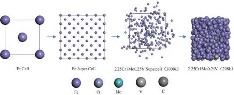
The microscale model of 2.25Cr1Mo0.25V was constructed by Haile’s element method [13]. Specifically, the pure iron cell consists of two Fe atoms with lattice parameters of 2.8644×2.8644×2.8644Å and a space group of IM-3M. Based on the lattice parameters of pure iron, the Fe cell was established and subjected to proportional element replacement, forming a 5×5×5 Fe supercell. The mass fraction of the main elements in 2.25Cr1Mo0.25V are shown in Table 1. The atomic ratio of each main element in the super cell was obtained by calculating the molar mass of the atom of each main element, and the original pure iron system was replaced according to the atomic ratios in the super cell.
The element replacement upset the balance of the original pure iron system, and could not simulate the random distribution of the elements in the 2.25Cr1Mo0.25V alloy. Therefore, the replaced Fe supercell was heated to 3,000 K, so that the alloy was fully melted.
Table 1. Mass fraction of the main elements in 2.25Cr1Mo0.25V
|
Element |
Mass fraction% |
Element |
Mass fraction % |
|
C |
0.11-0.15 |
Cu |
≤0.2 |
|
M |
0.3-0.6 |
As |
≤0.016 |
|
Si |
≤0.1 |
Sn |
≤0.015 |
|
P |
≤0.01 |
Ti |
≤0.03 |
|
S |
≤0.01 |
Sb |
≤0.003 |
|
Cr |
2.0-2.5 |
B |
≤0.002 |
|
Mo |
0.9-1.1 |
Ca |
≤0.015 |
|
Ni |
≤0.25 |
V |
0.25-0.35 |
Figure 1. Establishment of the microscale model of 2.25Cr1Mo0.25V
With the aid of a Nosé–Hoover thermostat, the simulation was carried out in a universal force field (UFF) at the temperature (3,000K) was maintained for 50ps. As shown in Figure 1, each atom of the supercell left the original position and entered into irregular motions, under the action of high temperature. Finally, the system temperature was reduced to 298K. After the simulation, the author obtained a microscale model of 2.25Cr1Mo0.25V with randomly arranged metal atoms. During the cooling process, the density of 2.25Cr1Mo0.25V gradually increased, while the system energy declined gradually before reaching an equilibrium.
(2) Microscale model of cemented carbide
Cemented carbide is produced from hard phase (e.g. WC, TiC and TaC) and binder phase (Co and Mo) by powder metallurgy. Our research targets the K20 cemented carbide tool, which consists of 91 % WC, 1 % NbC, and 8 % Co. For simplicity, this paper mainly discusses the WC in K20 cemented carbide tool, taking Co as the binder.
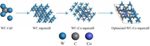
The carbon and tungsten atoms in the WC exist in a close-packed hexagonal structure with a space group of P-6M2. The C atom lies at the center of the lattice, whose fractional coordinates are (1/2, 2/3, 1/2) and lattice parameters is a=b=2.906 and c=2.837Å. Thus, a WC cell was created based on the said space group and lattice parameters, and a WC supercell was established through proportional replacing of the elements. Then, the atomic ratio of WC-Co was determined according to the mass fraction of Co in the cemented carbide and the molar mass of W, Co and C atoms, and the Co atom was doped into the WC supercell. Since the system became unstable after the addition of the Co atom, it is necessary to determine the optimal occupancy of Co atoms in the WC supercell (Figure 2).
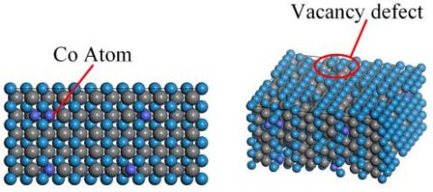
Before exploring element diffusion, there should be a cemented carbide diffusion model suitable for MD simulation. Limited by the production technology, many vacancy defects may occur in the materials for cemented carbide tool. To disclose how these defects affect the diffusion of cemented carbide, a cemented carbide model with a vacancy concentration of 0.2 was created based on the optimized cemented carbide supercell. However, the diffusion layer could not be established directly because the WC has a hexagonal structure while the microscale model of 2.25Cr1Mo0.25V is cubic. Hence, the cemented carbide crystal was cut along the (-1 1 0) direction to create a cleave surface. The resulting microscale model of cemented carbide is illustrated in Figure 3 below.
Figure 2. Microscale model of the original cemented carbide
Figure 3. Microscale model of cemented carbide(3) Microscale model of diffusion layer
(3) Microscale model of diffusion layer
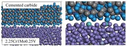
1) Model establishment. The microscale model of diffusion layer was established from the microscale models of the 2.25Cr1Mo0.25V and the cemented carbide with a cleave surface, and under the following assumptions: the 2.25Cr1Mo0.25V and the cemented carbide are in the same lattice with periodic boundary conditions during the MD simulation; the total volume of the diffusion layer remains constant in the diffusion process; the system and external environment exchange energy but not material [14]. The established microscale model for diffusion layer is presented as Figure 4.
Figure 4. Microscale model for diffusion layer
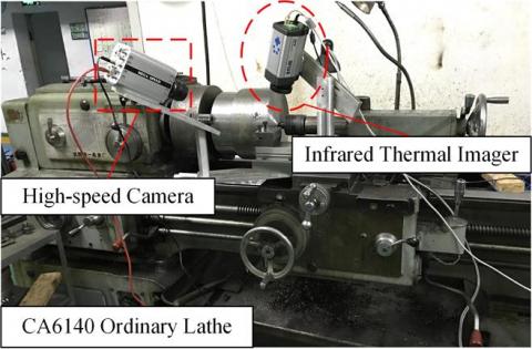
2) Temperature boundary condition. A cutting experiment was carried out on a CA6140 ordinary lathe to determine the temperature range for bond breakage, that is, the temperature boundary condition of MD simulation. The temperature of the tool-chip interface was collected in real time by a ThermoVision A40M infrared thermal imager, and the experimental process was shot continuously by a high-speed camera at 1,000 fps. When the bond breakage took place, the broken blade was removed and the breakage profile of the tool was observed by a super-depth microscope and a scanning electron microscope (SEM), and the tool-chip interface was analyzed by an energy spectrum analyzer. The experiment platform is illustrated in Figure 5 below.
Figure 5. Experiment platform
After a long time of cutting, obvious bond breakage was observed on the tool-chip interface. Then, the super-depth microscope was adopted to observe the bond breakage morphology of the blade after cutting. The observed morphology is displayed in Figure 6 below.
Figure 6. Bond breakage morphology on tool-chip interface
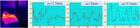
The experiment was carried out by single factor analysis, the cutting speed was kept at v=60 m/min, and the feed was set to f=0.15 mm/r. The back-cutting depth was taken as the variable to study the cutting temperature under different cutting parameters by infrared thermal imager. The temperature curves under different back-cutting depths are shown in Figure 7 below.
Figure 7. Temperature curves under different back-cutting depths
2.2 MD Simulation
(1) Diffusion simulation
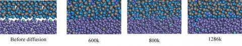
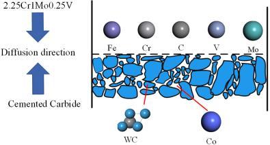
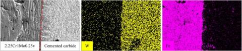
MD simulation is a numerical integration method based on atomic potential function. It has been widely adopted to study the deformation behavior of materials under various actions (e.g. tension, compression, bending, twisting and nanofabrication) [15-18]. This method is hailed as the bridge between macroscale and microscale, because of its abilities to accurately describe the microscale features and reproduce the macroscale performance of complex condensed-matter physics systems. The popular MD software include LAMMPS and the Forcite module in the Materials Studio software package. The latter is adopted for our MD simulation. According to Fick’s law of diffusion and previous studies [7], the diffusion of solids is mainly affected by temperature and concentration gradients. Therefore, in our simulation, the effect of cutting temperature on element diffusion was studied with temperature as the main variable. Three temperatures, namely, 800 K, 1,000 K and 1,286 K, were selected from the measured temperature range for the simulation. The simulation lasted for 50ps in a UFF with a time step of 1fs. The temperature was controlled by a Nosé–Hoover thermostat. The diffusion model was shown in Figure 8 and the diffusion direction are recorded in Figure 9. It can be seen that different degrees of diffusion occurred between the cemented carbide and 2.25Cr1Mo0.25V under different temperatures. Some Fe, Mo, V and Cr atoms entered the interior of the cemented carbide crystal, while the 2.25Cr1Mo0.25V lost some of its W atoms and Co atoms. The diffusion trends agree well with those in the energy spectrum image (Figure 10).
Figure 8. MD simulation model
Figure 9. Schematic diagram
Figure 10. Microscale diffusion and energy spectrum of atoms on tool-chip interface
(2) Bonding energy simulation
The bonding strength of crystals depends on the interaction between the particles of the crystal, i.e. the bonding force of the chemical bonds between atoms. The intensity of the interaction can be measured by the bonding energy. In essence, the bonding energy refers to the energy released by the free microscopic particles when being combined into crystals, which equals the energy required to destroy the crystal. Previous studies [11] have demonstrated the major impact of bonding energy on the mechanical properties of the material.
Through the cutting experiment and MD simulation, it is learned that, under the bond breakage temperature, element diffusion occurred on the interface between 2.25Cr1Mo0.25V and the cemented carbide; some Fe, Cr, Mo and V atoms entered the cemented carbide. In the diffusion layer, some W atoms were lost and the bonding form changed between the atoms in the layer.
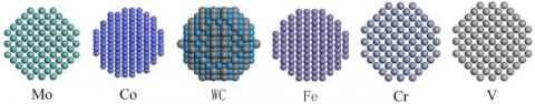
Considering the above, the author decided to study the post-diffusion interaction between the particles in the deterioration layer of cemented carbide from the perspective of bonding energy. The grain of each element was simplified into atomic groups, creating atomic groups of Fe, Co, Cr, Mo and V elements with a diameter of 10Å (Figure 11).
Figure 11. Atomic groups
The bonding energy and interaction parameters between particles were calculated by the Blends atom simulation module, which is inspired by the Flory-Higgins model [19]. In this module, the bonding energy is computed using the configuration of the paired data points, the relative position, and the exclusive volume constraint method; the results are averaged by the Boltzmann constant, before determining the temperature-dependent interaction parameters.
During the simulation, the WC atomic group was defined as base, and the other atomic groups were defined as screens. The other simulation parameters are as follows: the force field was set to UFF, the energy sample was 107, the energy group spacing was 0.02 kcal/mol, and the temperature range was 300~1,286 K.
3.1 Discussion of diffusion features
Wang et al. [20] suggested that diffusion is the only transport method in solid materials. When two chemically intimate solids (e.g. iron and carbon) are put together and heated to a certain temperature, the atoms of these solids will mutually diffuse to form a new alloy. Once solid diffusion occurs, the atoms in the solids will move in a direction that reduces the concentration difference, that is, down the energy gradient [21]. This is because the atoms, under the action of various factors, tend to leave the initial equilibrium positions in seek of new equilibrium positions.
The diffusion degree must be quantified to accurately measure the effect of temperature on diffusion. Thus, the diffusion coefficient (D) was introduced, which can describe how fast the solute atoms diffuse in the solvent. Then, the mean square dislocation (MSD) of each atom in the system was computed by the Forcite module. Taking the MSD as an intermediate variable, the D of each atom can be derived by the Einstein method [22].
The MSD can be calculated as:
$\operatorname{MSD}(t)=\frac{1}{n} \sum_{i=1}^{n}\left\langle\left|r_{i}(t)-r_{i}(o)\right|^{2}\right\rangle$ (1)
where, ri(t) is the position of the atom i at time t; n is the number of atoms in the system.
The D can be expressed as:
$D=\frac{1}{6} \frac{\partial}{\partial t}\left[\frac{1}{n} \sum_{i=1}^{n}\left\langle\left|r_{i}(t)-r_{i}(o)\right|^{2}\right\rangle\right]$ (2)
The expression is usually simplified as:
$D=\frac{1}{6}(M S D)$ (3)
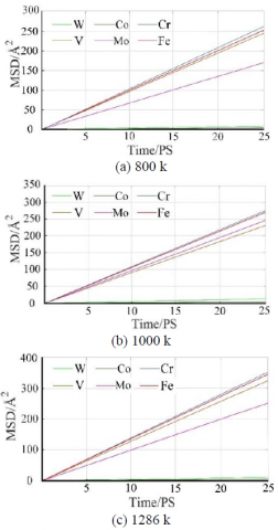
Figure 12. MSD-time curve of main elements
The atom positions at each time point were fitted on Matlab, yielding the MSD-time curve of the main elements in cemented carbide and 2.25Cr1Mo0.25V (Figure 12). To ensure the accuracy of the D, the non-Einstein diffusion region was removed during the fitting of the MSD curve.
Table 2. The D value of each main element (Å2/ps)
|
T(k) |
Fe |
Mo |
Cr |
W |
Co |
V |
|
800 |
9.97 |
6.68 |
9.98 |
0.15 |
0.01 |
9.54 |
|
1000 |
11.62 |
9.98 |
12.09 |
0.20 |
0.02 |
10.06 |
|
1286 |
14.22 |
10.10 |
14.37 |
0.21 |
0.04 |
14.12 |
The fitted MSD value of each element was substituted into equation (3) to obtain the D value of each main element at the corresponding temperature. The specific values are listed in Table 2.
As shown in Table 2, the D value is positively correlated with the diffusion ability of an atom. Under each temperature, the 2.25Cr1Mo0.25V atoms moving towards the cemented carbide had greater D values than the cemented carbide atoms moving towards the 2.25Cr1Mo0.25V. This means each 2.25Cr1Mo0.25V atom boasts greater diffusion ability than its counterpart in cemented carbide. From Figure 12 and Table 2, it can be seen that the diffusion degree increased with the temperature, and peaked at 1,286 K. The trend is consistent with the Fick’s law of diffusion.
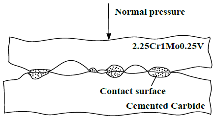
Figure 13. Tool-chip interface
Eiji explained that the role of pressure in the diffusion process is to press the two materials into the range of atomic range [6]. As shown in Figure 13, the interface between cemented carbide and 2.25Cr1Mo0.25V is rough during the machining. On the microscale, the protrusions and gullies continued to spread on the surfaces of the two metals. In general conditions, it is difficult to make atoms enter the range of atomic force on either side of the interface. In other words, the diffusion conditions are hard to achieved under normal conditions. During the cutting process, however, the cutting force is sufficiently large, such that the two metal surfaces are in close contact. In this case, many atoms can enter the range of atomic force. From the microscopic angle, the high pressure of the cutting process only ensures the close contact of the two atomic layers. In the simulation, the distance between the two materials was on the angstrom level, which is well within the range of atomic force. Thus, pressure is not an important influencing factor of solid diffusion, and is neglected in our discussion.
As mentioned above, temperature and concentration gradients are two leading factors affecting diffusion. In our research, the MD simulation lasted only 50 ps and the opposite atom concentration was zero in the microscale models of cemented carbide and 2.25Cr1Mo0.25V. Thus, there existed a concentration gradient to initiate the diffusion. As a result, the effect of temperature on diffusion is discussed in details below.
The expression of the D can be rewritten as [23]:
$D=\alpha^{2} P \Gamma$ (4)
where, α2 is the square of atomic diffusion distance; P is the probability of atomic diffusion; Γ is the frequency of atomic diffusion.
Unlike those in liquids and gases, the diffusion of elements in solids needs to overcome the huge bonding energy, i.e. the energy barrier. That is why the solid diffusion is very slow under normal conditions. Fortunately, the high temperature of the cutting process creates a favorable condition for solid element diffusion. In the cutting environment, the atomic diffusion distance hinges on the temperature and the microscopic mechanism of atomic diffusion.
On the effect of temperature, the total energy of the system increases with the temperature, making it easier to reach the energy to activate the diffusion of each element. Besides, the vacancy concentration is high and the thermal motion of atoms is vigorous at high temperatures. In this case, an atom can easily enter the range of interaction between other atoms along the crystal gap and vacancies. The diffusion behavior of the atom is thus promoted. The diffusion speed is slow if the temperature is below the atomic recrystallization temperature, and much faster if otherwise. For industrial pure metal, the recrystallization temperature is 35 %~45 % of its melting point. For alloy, recrystallization temperature is 40 %~90 % of its melting point. As the main component of cemented carbide, the WC starts to melt under 3,143 K. Thus, the recrystallization temperature of WC falls in 1,421~2,856 K. The temperature measured in the cutting experiment was 800~1,286 K, failing to reach the recrystallization temperature of WC. However, the measured temperature fell in the recrystallization temperature range of 2.25Cr1mo0.25V. As a result, the 2.25Cr1Mo0.25V atom diffused much faster than W atoms and Co atoms in the cemented carbide.
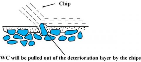
The microscopic mechanism of atomic diffusion directly bears on the energy to activate atomic diffusion. The atoms in vacancies are the easiest to diffuse because they have the highest potential energy. Vacancy diffusion is the most common diffusion mechanism, followed by interstitial diffusion and quasi-interstitial diffusion. By contrast, the atoms at the lattice position have the lowest potential energy. Thus, a huge amount of energy is needed to activate translocation diffusion. As mentioned above, a vacancy concentration of 0.2 was set for the cemented carbide diffusion model. Hence, the atomic diffusion of 2.25Cr1Mo0.25V mainly followed the vacancy diffusion mechanism. With the growth of temperature, the atoms were more likely to surpass the energy barrier, and other diffusion mechanisms gradually emerged. As the cutting progressed, numerous Fe, Cr, Mo and V atoms entered the diffusion deterioration layer, and a large amount of W atoms were lost, leading to changes of tool material composition. Through this process, the tool material was deteriorated and its mechanical strength declined gradually. The bond breakage occurred when the strength dropped to a certain threshold (Figure 14).
Figure 14. Diffusion deterioration layer
3.2 Discussion of Blends features
The mixing and separation between binary systems in the Blends module can be calculated by the Flory-Higgins model [19]:
$\frac{\Delta G}{R T}=\frac{\phi_{b}}{n_{b}} \ln \phi_{b}+\frac{\phi_{s}}{n_{s}} \ln \phi_{z}+\chi \phi_{b} \phi_{z}$ (5)
where, △G is the mixture free energy per mole of microscopic particles; Φi is the volume fraction of the i-th component; niis the miscibility of the i-th component; χ(chi) is the interaction parameter. The first two terms represent the mixing entropy and the last term reflects the interaction free energy.
In the diffusion deterioration layer of cemented carbide, WC and such elemental metals as Co, Fe and Cr appear as a solid solution. It is necessary to evaluate the solid solubility of each element before determining the structural stability of the diffusion deterioration layer. Here, the solid solubility is explored using the interaction parameter χ below:
$\chi=\frac{E_{\operatorname{mix}}}{R T}$ (6)
where, Emix is the mixing energy; R is the gas constant; T is the absolute temperature. If χ is negative or small, the two particles have good miscibility at the current temperature. Otherwise, the two particles tend to separate. If the χ is sufficient large, the free energy of the mixture will overcome the mixed entropy and split the mixture into two separate phases.
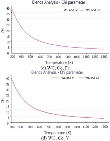
As shown in Figure 15 below, when the cutting temperature was on the rise, the χ values of all atomic groups exhibited a downward trend and eventually tended to zero. This trend shows that the solid solubility of WC (base) and Co, Cr, Fe, Mo and V (screen) increases with the cutting temperature. Within the range of the cutting temperature, WC can forma stable solid solution alloy with proper concentrations of screen elements. With the decline in the cutting temperature, the solubility of WC and all screen elements were reduced, and the particles were more likely to be separated, adding to the difficulty in the formation of alloy.
It can be seen from Figure 15(b) and Table 3, under the normal temperature of 298K, the χ values of WC and Mo were lower than those of other elements, and decreased with the increase of temperature. In terms of solid solubility, the WC has similar solubilities in Cr, V and Co, and an extremely high solubility in Mo. Thus, WC and Co can easily form a stable solid solution. Considering the low presence of Mo in the 2.25Cr1Mo0.25V alloy, the diffusion of Mo, Cr and V elements was not viewed as the main cause of bond breakage. This simulation result is consistent with the findings in previous research: when the cemented carbide is sintered, the WC is less soluble in Fe than in Co, and the mushy zone (the range of C content) is narrow in the WC-Fe system, making it difficult to obtain a solid solution two-phase alloy of WC-Fe [24].
Comparing Figure 15(c) and Table 3, it is observed that the χ curve of WC-Co was only slightly higher than that of WC-Fe. Co and Fe are congeners. With the rising temperature, the WC is more and more soluble in Co than in Fe. Thus, it can be concluded that WC-Fe and WC-Co have similar ranges of bond breakage temperature, and the small difference is negatively correlated with temperature. Under element diffusion, the WC is partially combined with Fe into WC-Fe alloy. However, this alloy may produce η phase (FexWxCx) due to the carbon deficiency during metallurgy. The η phase exists as a malignant defect in the structure of cemented carbide, and seriously undermines the physical and chemical properties of the alloy. The η phase is often suppressed by carbon black, which is not available in the random diffusion process of our simulation. Thus, the physical and chemical properties of the tool material continued to worsen in the cutting process. When the deterioration reached a certain threshold, the tool material broke down and was carried away from the tool surface with the chips.
Figure 15. Interaction parameter χ
Table 3. Results of blends simulation
|
Base |
Screen |
χ(298k) |
Emix(298k) |
Ebs avg(298k) |
|
WC |
Co |
37.68 |
22.31 |
-1.45 |
|
WC |
Fe |
38.15 |
22.59 |
-1.38 |
|
WC |
Cr |
36.60 |
21.67 |
-1.59 |
|
WC |
Mo |
28.49 |
16.87 |
-2.84 |
|
WC |
V |
36.69 |
21.72 |
-1.57 |
3.3 Discussion of bonding energy
The strength of the bonding ability between crystals can be described as the bonding energy, which is defined as the difference between the total energy of a crystal and that of its N free atom states when the crystal is in a steady state. The bonding energy can also be understood as the energy released when a free atom (ion or molecule) is combined into a crystal, or the energy required to split a free atom off a crystal. The bonding energy between the atomic group of WC and that of any screen element helps to judge the fracture of cemented carbide under the cutting force and cutting vibration.
Bonding energy can quantify the strength of interface bonding. The higher the bonding energy, the more energy is needed to destroy the interface. The strength of interface bonding can be expressed as:
$W=\left(E_{\text {interface }}-E_{\mathrm{a}}-E_{\mathrm{b}}\right) / A$ (7)
where, Einterface is the total energy of the interface; Ea is the energy of surface a; Eb is the energy of surface b; A is the square of interface.
The directions of the bonding energy were calculated by the MS software. Note that the negative sign means the bonding between the two particles releases energy, and the absolute value stands for the level of bonding energy.
Table 3 shows that WC and Mo had stronger bonding energy than the combination between WC and any other screen element. As stated above, the low content of Mo in the 2.25Cr1Mo0.25V is not an important cause. The bonding energy of WC-Co was slightly higher than that of WC-Fe. From the simulation results and χ value analysis, it is known that Fe is the key element in the diffusion of cemented carbide. With the lowest bonding energy at normal temperature, the WC-Fe interface was the weakest and the most likely to break down in our research.
Under the same concentration, the bonding strength of WC-Co alloy is 1.5~2 times that of WC-Fe alloy. During the smelting of cemented carbide, a small amount of Cu is often added to enhance the performance of WC-Fe-based alloy. Even so, the bonding strength of WC-Fe-based alloys is only 60 %~70 % of that of WC-Co alloys. The diffusion deterioration layer of cemented carbide had even weaker mechanical properties and bonding ability than WC-Fe bonding, as multiple elements combined and multiple phases formed under the random diffusion in the cutting process. As a result, the material on the rake face of the cutting tool witnessed a decline in mechanical properties.
As shown in Figure 16, an unstable intermetallic compound was dissolved and formed in the range of the cutting temperature. If the cutting is interrupted, the changing temperature will break WC-Fe and other elemental bonding, creating local microcracks in the unstable solid solutions. The microcracks will develop between the tool materials, and eventually break the bond between WC and other element in the deterioration layer. The broken parts will leave the rake face of the cutting tool as chips.
Figure 16. Diffusion deterioration layer of the bonding interface
This paper carries out a cutting experiment and an MD simulation of the cutting of 2.25Cr1Mo0.25V H2S-resistant steel with carbide cutter, aiming to identify the causes to the bond breakage on the rake face of the cutter. Through the results analysis, the following conclusions were put forward:
(1) The occurrence of bond breakage was confirmed by the cutting experiment. It is also confirmed that element diffusion will happen between cemented carbide and 2.25Cr1Mo0.25V in the temperature range of the bond failure. With a relatively low diffusion activation energy, 2.25Cr1Mo0.25V is more soluble than hard alloy to the cemented carbide. As the W element is gradually lost in the cutting process, the mechanical properties of the cemented carbide continue to decline. The bond breakage will occur when the decline reaches a certain threshold.
(2) Through Blends molecular simulation, it is concluded that the solid solubilities of the WC to Co, Fe, Cr, Mo and V all increases gradually with the rising temperature. In the temperature range of the bond failure, the WC can form a stable alloy with proper concentrations of Co and other elements in the 2.25Cr1Mo0.25V. However, it is difficult to form a stable solid solution with Fe.
(3) In the temperature range of the bond failure, the bonding energy of Fe atom and the WC is weaker that of the other elements and the WC. As a key element in 2.25Cr1Mo0.25V, Fe is the leading influencing factor on the bonding ability of WC particles in the cemented carbide deterioration layer. With the increased entry of Fe into the deterioration layer and the gradual loss of W element, the bonding ability of the material in the cemented carbide diffusion deterioration layer continues to decrease, leading to poor mechanical properties. In this case, the tool material is prone to suffer from the bond breakage, under the strong cutting force, temperature change and vibration impact of heavy-duty intermittent cutting.
This work was supported by the National Natural Science Foundation of China (Grant No.51575146) and 2017 open fund project of CAD/CAM University Engineering Research Center in Fujian Province, China (Grant No. K201709). The authors are grateful to everyone who contributed to this research, including the technicians who helped to implement the various experiments and analysis.
[1] Zheng, M.L., Chen, J.G., Li, Z., Zhang, W., Li, P.F., Xie, H.H. (2018). Experimental study on elements diffusion of carbide tool rake face in turning stainless steel. Journal of Advanced Mechanical Design Systems and Manufacturing, 12(4): 1-12. https://doi.org/10.1299/jamdsm.2018jamdsm0085
[2] Chen, J.G., Zheng, M.L., Zhang, W., Sun, Y.S., Tang, Q.H. (2018). Research on the theoretical model of the rake face wear of carbide cutting tool. The International Journal of Advanced Manufacturing Technology, 98(1-4): 421-429. https://doi.org/10.1007/s00170-018-2303-4
[3] Murugan, S.S. (2018). Processing and characterisation of LM30 alloy + graphite reinforced composite through gravity and centrifugal casting, Annales de Chimie - Science des Matériaux, 42(4): 555-564. https://doi.org/10.3166/ACSM.42.555-564
[4] Chen, J.G., Zheng, M.L., Li, P.F., Feng, J., Sun, Y.S. (2017). Experimental study and simulation on the chip sticking–welding of the carbide cutter’s rake face. International Journal on Interactive Design and Manufacturing, 12(4): 1309-1319. https://doi.org/10.1007/s12008-017-0403-2
[5] Cheng, Y.N., Liu, L., Lu, Z.Z., Guan, R., Wang, T. (2015). Study on the adhering failure mechanism of cemented carbide inserts and element diffusion model during the heavy-duty cutting of water chamber head. The International Journal of Advanced Manufacturing Technology, 80: 1833-1842. https://doi.org/10.1007/s00170-015-7166-3
[6] Eiji, U. (1982). The study of cutting and grinding. Mechanical Industry Press, Beijing.
[7] Zhang, S., Li, J.F., Deng, J.X., Li, Y.S. (2009). Investigation on diffusion wear during high-speed machining Ti-6Al-4V alloy with straight tungsten carbide tools. The International Journal of Advanced Manufacturing Technology, 44(1-2): 17-25. https://doi.org/10.1007/s00170-008-1803-z
[8] Tong, W.P., Tao, N.R., Wang, Z.B., Lu, J., Lu, K. (2003). Nitriding iron at lower temperatures. Science, 299(5607): 686-688. https://doi.org/10.1126/science.1080216
[9] Shenouda, S.S., Langer, G.A., Katona, G.L., Daróczi, L., Csik, A., Beke, D.L. (2014). Production of NiSi phase by grain boundary diffusion induced solid state reaction between Ni2Si and Si(100) substrate. Applied Surface Science, 320: 627-633. https://doi.org/10.1016/j.apsusc.2014.09.071
[10] Christensen, M., Dudiy, S., Wahnström, G. (2002). First-principles simulations of metal-ceramic interface adhesion: Co/Wc versus Co/Tic. Physical Review B, 65(4): 17002-17011. https://doi.org/10.1103/PhysRevB.65.045408
[11] Feest, E.A. (1994). Interfacial phenomena in metal-matrix composites. Composites, 25(2): 75-86. https://doi.org/10.1016/0010-4361(94)90001-9
[12] Han, X.S. (2007). Investigation atomic level micromechanism about tool wear in the case of nanometric cutting using molecular dynamics method. Chinese Journal of Mechanical Engineering, 43(9): 107-112. http://dx.chinadoi.cn/10.3321/j.issn:0577-6686.2007.09.022
[13] Haile, J.M., Johnston, I., Mallinckrodt, A.J., McKay, S. (1993). Molecular dynamics simulation: elementary methods. Computers in Physics, 7(6): 625. https://doi.org/10.1063/1.4823234
[14] Jian, X. (2016). Atomistic simulation of the interaction of helium with dislocation in nickel. Master’s thesis, University of Chinese Academy of Science, Beijing
[15] Liu, B., Liu, G., Xiao, B., Yan, J. (2018). Molecularly imprinted electrochemical sensor for the determination of sulfamethoxazole. Journal of New Materials for Electrochemical Systems, 21(2): 77-80.
[16] Chen, S.D., Ke, F.J., Bai, Y.L. (2007). Atomistic investigation of the effects of temperature and surface roughness on diffusion bonding between Cu and Al. Acta Materialia, 55(9): 3169-3175. https://doi.org/10.1016/j.actamat.2006.12.040
[17] Denis, S., Ronald, E.M. (2006). Atomic-scale simulation of nanoindentation-induced plasticity in copper crystals with nanometer-sized nickel coatings. Acta Materialia, 54(1): 33-45. https://doi.org/10.1016/j.actamat.2005.08.030
[18] Silva, E.Z.D., Silva, A.J.R.D., Fazzio, A. (2004). Breaking of gold nanowires. Computational Materials Science, 30(1-2): 73-76. https://doi.org/10.1016/j.commatsci.2004.01.011
[19] Flory, P.J. (1953). Principles of Polymer Chemistry. Cornell University Press, Ithaca
[20] Wang, Z.B., Tao, N.R., Tong, W.P., Lu, J., Lu, K. (2003). Diffusion of chromium in nanocrystalline iron produced by means of surface mechanical attrition treatment. Acta Materialia, 51(14): 4319-4329. https://doi.org/10.1016/s1359-6454(03)00260-x
[21] Xu, Y.Q. (2017). Research on Sillicon Diffusion in Preparing Sillicon Steel by CVD Method. East China University of Science and Technology, Shanghai
[22] Allen, M.P., Tildsley, D. (1987). Computer Simulation of Liquids. Claredon Press, Oxford
[23] Shi, D.K. (1999). Foundation of Materials Science. Mechanical Industry Press, Beijing
[24] Zhao, X.J. (2004). Microstructures and Properties of Fusion Welding Interface Between Cemented Carbides and Steels. Dalian Jiaotong University, Dalian.