Younes Menni | Ali J. Chamkha | Ahmed Azzi | Chafika Zidani* | Boumédiène Benyoucef
OPEN ACCESS
Numerical studies of the steady incompressible turbulent forced-convection flow around top and bottom surface-mounted staggered baffles as a function of the Reynolds number are considered in this recent contribution in order to examine two various geometries of solid-type baffles, a flat rectangular baffle (simple obstacle) and an arc-shaped baffle (new obstacle). Air is the heat transfer fluid with the Reynolds numbers ranging from 12 × 103 to 32 ×103. The dynamic thermo-energy model of air is governed by the Reynolds averaged Navier-Stokes equations with the Standard k-ε turbulence model and the energy equation. These equations are discretized by the Quadratic Upstream Interpolation for Convective Kinetics Differencing (QUICK) numerical scheme and the Semi-Implicit Pressure Linked Equation (SIMPLE) algorithm is adopted. The impacts of obstacle geometries as well as flow rates are treated. The numerical plots are presented in terms of velocity, temperature, heat transfer, friction, and thermal enhancement factor, for the entire configuration under study and for various selected stations, namely, before, after and between the two baffles.
shell-and-tube heat exchangers, turbulence, heat transfer, friction, Reynolds number
Shell-and-tube heat exchangers (STHXs) are used in several sectors and in very diverse fields. The improvement of their performance has been and still is the concern of theorists and practitioners. Founti and Whitelaw [1] carried out an experiment using the Laser Doppler Anemometry (LDA) technique to deduce the velocity fields in an axisymmetric heat exchanger with baffle plates on the shell side-surface. Valencia and Cid [2] numerically simulated the unsteady turbulent flow of air and heat transfer in a channel with two periodically mounted square bars arranged side by side to the approaching flow with a modified version of the standard k-ε turbulence model. Dutta and Hossain [3] investigated the local heat transfer characteristics and the associated frictional head loss in a rectangular channel with inclined solid and perforated baffles. Nasiruddin and Kamran Siddiqui [4] reported the heat transfer enhancement in a heat exchanger tube by installing a baffle. Ozceyhan et al. [5] submitted a numerical study on heat transfer and friction loss characteristics of a tube with circular cross sectional ring inserts. Ali et al. [6] reported experimental investigations on steady state forced convection heat transfer from the outer surface of horizontal triangular surface cylinders in cross flow of air. Wang et al. [7] numerically and experimentally investigated the flow and heat transfer characteristics inside a rectangular channel embedded with pin fins. Rao et al. [8] conducted an experimental and numerical study to investigate the flow friction and heat transfer performance in rectangular channels with staggered arrays of pin fin-dimple hybrid structures and pin fins in the Reynolds number range of 8200-54,000. Alam et al. [9] experimentally investigated the effect of geometrical parameters of the V-shaped perforated blocks on heat transfer and flow characteristics of a rectangular duct. Nanan et al. [10] numerically and experimentally carried out a comparative investigation on the flow and heat transfer associated with baffle turbulators with different designs: typical straight baffles, straight cross-baffles, straight alternate-baffles, twisted-baffles, alternate twisted-baffles and twisted cross-baffles. Li and Gao [11] numerically studied the three-dimensional turbulent flow and heat transfer in the channels with or without baffles. Hosseinnezhad et al. [12] numerically investigated the turbulent flow of water/Al2O3 nanofluid in a tubular heat exchanger with two twisted-tape inserts in the three-dimensional coordinate. Other similar works can be found in the literature as Ismael et al. [13], Rashad et al. [14-15], Sivasankaran et al. [16], Ahmadi et al. [17], Vasanthakumari and Pondy [18], Tahmasebi et al. [19], Mehryan et al. [20-22], Demartini et al. [23], Ghalambaz et al. [24-26], Chamkha et al. [27]. Various geometries and different boundary conditions were used in those studies.
In this recent analysis, the dynamic thermal energy structure of the incompressible steady fluid flow in a 2D channel of rectangular section is examined and analyzed, using a CFD technique. The channel has arc and/or flat rectangular-shaped obstacles which are placed on the top and bottom surfaces in a staggered manner, as numerically and experimentally presented in more detail by Demartini et al. [23]. The mean velocity and total temperature fields, axial velocity and skin friction profiles, frication factor, Nusselt numbers, and thermal enhancement factor are presented for Reynolds numbers ranging from 12 × 103 to 32 × 103.
The computational domain concerned, shown in Figure 1, is a 0.554 m long (L) rectangular cross section channel, with 0.146 m height (H), 0.176 m aeraulic diameter (Dh), and a width (W) of 0.193 m. Two baffles are placed on opposite duct surfaces. Two variously shaped obstacles, i.e., flat rectangular (see Figure 1 (a), and 60° arc-shaped (see Figure 1 (b), under turbulent condition are compared in a staggered manner.
Figure 1. Geometries under study: (a) channel with staggered flat rectangular obstacles, (b) channel with staggered arc-shaped obstacles
To present and examine the flow dynamics and the heat transfer of air in the channel conduit, the following simplifying assumptions are made: (i) the fluid (air) is considered incompressible, Newtonian, and turbulent at constant properties; (ii) Body forces, viscous dissipation, and radiation heat transfer are ignored.
The thermal aerodynamic aspects of airflow are governed by the Reynolds averaged Navier-Stokes (RANS), and energy equations.
Continuity equation
$\frac{\partial }{\partial {{x}_{i}}}\left( \rho {{u}_{i}} \right)=0$ (1)
Momentum equation
$\frac{\partial }{\partial {{x}_{i}}}\left( \rho {{u}_{i}}{{u}_{j}} \right)=\frac{\partial }{\rho {{x}_{i}}}\left[ \mu \left( \frac{\partial {{u}_{i}}}{\partial {{x}_{j}}}-\rho \overline{u_{i}^{'}u_{j}^{'}} \right) \right]-\frac{\partial P}{\partial {{x}_{i}}}$ (2)
with
$-\rho \overline{u_{i}^{'}u_{j}^{'}}={{\mu }_{t}}\left( \frac{\partial {{u}_{i}}}{{{x}_{j}}}+\frac{{{u}_{j}}}{{{x}_{i}}} \right)-\frac{2}{3}\left( \rho k+{{\mu }_{t}}\frac{\partial {{u}_{i}}}{\partial {{x}_{j}}} \right){{\delta }_{ij}}$ (3)
where ui and uj are mean velocity components in xi and xj directions, δij is the Kroeneker delta and μt is the eddy viscosity defined as:
${{\mu }_{t}}=\rho {{C}_{\mu }}\frac{{{k}^{2}}}{\varepsilon }$ (4)
Energy equation
$\frac{\partial }{\partial {{x}_{i}}}\left( \rho {{u}_{i}}T \right)=\frac{\partial }{\rho {{x}_{i}}}\left( \left( \Gamma +{{\Gamma }_{t}} \right)\frac{\partial T}{\partial {{x}_{j}}} \right)$ (5)
where Γ and Γt are molecular thermal diffusivity and turbulent tharmal diffusivity, repectively and are given by
$\begin{matrix} \Gamma ={\mu }/{\Pr }\; & \text{and} & {{\Gamma }_{t}}={{{\mu }_{t}}}/{{{\Pr }_{t}}}\; \\ \end{matrix}$ (6)
The standard k-ε model is defined by two transport equations, one for the turbulent kinetic energy (k) and the other for the dissipation rate (ε) as given below
$\frac{\partial }{\partial {{x}_{j}}}\left( \rho k{{u}_{j}} \right)=\frac{\partial }{\partial {{x}_{j}}}\left[ \left( \mu +\frac{{{\mu }_{t}}}{{{\sigma }_{k}}} \right)\frac{\partial k}{\partial {{x}_{j}}} \right]+{{G}_{k}}+\rho \varepsilon $ (7)
$\frac{\partial }{\partial {{x}_{j}}}\left( \rho \varepsilon {{u}_{j}} \right)=\frac{\partial }{\partial {{x}_{j}}}\left[ \left( \mu +\frac{{{\mu }_{t}}}{{{\sigma }_{\varepsilon }}} \right)\frac{\partial \varepsilon }{\partial {{x}_{j}}} \right]+{{C}_{1\varepsilon }}\frac{\varepsilon }{k}-{{C}_{2\varepsilon }}\rho \frac{{{\varepsilon }^{2}}}{k}$ (8)
In these equations, Gk represents turbulence kinetic energy generated by the mean velocity gradients. The empirical constants for the standard k-ε model are assigned the following values [28]: Cμ = 0.99; C1ε = 1.44; C2ε = 1.92; σk = 1.0 and σε = 1.3.
The flow Reynolds number (Re) is defined as
$\operatorname{Re}=\frac{\rho \overline{U}{{D}_{h}}}{\mu }$ (9)
where $\overline{U}$ is the the average fluid velocity at the intake of the computational domain and Dh is the aedraulic diameter, which is expressed as follows:
${{D}_{h}}=4HW/2(H+W)$ (10)
The local skin friction coefficient is given by
${{C}_{f}}=\frac{2.{{\tau }_{w}}}{\rho .{{\overline{U}}^{2}}}$ (11)
The average skin friction coefficient is given by
$f=\frac{\left( {\Delta P}/{L}\; \right){{D}_{h}}}{\frac{1}{2}\rho {{\overline{U}}^{2}}}$ (12)
where τw presents the shear-stress to the wall.
The local Nusselt number (Nux) is written as
$N{{u}_{x}}=\frac{{{h}_{x}}{{D}_{h}}}{{{k}_{f}}}$ (13)
and the average Nusselt number (Nu) is obtained by
$Nu=\frac{1}{L}\int{N{{u}_{x}}\partial x}$ (14)
The thermal enhancement factor (TEF) is given by:
$TEF={\left( {Nu}/{N{{u}_{0}}}\; \right)}/{{{\left( {f}/{{{f}_{0}}}\; \right)}^{{1}/{3}\;}}}\;$ (15)
The quantities Nu0 and f0 are the average Nusselt number and the friction factor of the smooth channel, respectively.
Dittus and Boelter correlation has the form:
$\begin{matrix} N{{u}_{0}}=0.023{{\operatorname{Re}}^{0.8}}{{\Pr }^{0.4}} & \text{for} & \operatorname{Re}\ge {{10}^{4}} \\ \end{matrix}$ (16)
The Petukhov correlation has the form:
$\begin{matrix} {{f}_{0}}={{\left( 0.79\ln \operatorname{Re}-1.64 \right)}^{-2}} & \text{for} & 3\times {{10}^{3}}\le \operatorname{Re}\le 5\times {{10}^{6}} \\ \end{matrix}$ (17)
The thermal physical properties (density ρ, dynamic viscosity μ, thermal conductivity λf) of air with Tin = 300 K are constant. A uniform 1D velocity (u = Uin, v = 0) is applied at the inlet of the conduit, as shown by Demartini et al. [23], and Nasiruddin and Kamran Siddiqui [4]. A turbulence intensity of 2 % is used at the inlet, as reported by Demartini et al. [19]. Non slip and impermeability boundary conditions are imposed at the channel and obstacle surfaces, as reported by Demartini et al. [23]. In the channel outlet, the atmospheric pressure was adopted. A condition of constant surface temperature (Tw = 375 K) is applied from the upper channel wall, but the lower surface is maintained at an adiabatic condition.
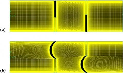
Air is the heat transfer fluid with the Reynolds numbers ranging from 12 × 103 to 32 × 103. The dynamic thermo-energy model of air is governed by the Reynolds averaged Navier-Stokes equations with the Standard k-ε turbulence model and the energy equation. These equations are discretized by the Quadratic Upstream Interpolation for Convective Kinetics Differencing (QUICK) numerical scheme (Leonard and Mokhtari [29]), and Semi-Implicit Pressure Linked Equation (SIMPLE) algorithm (Patankar, [30]) is adopted. A structured, quadrilateral, non-uniform mesh with refinements near the all solid boundaries in the two directions is adopted (see Figure 2 (a) and (b)). Various nodes are verified and a cell of 245 and 95 nodes in X and Y directions, respectively, is adopted.
Figure 2. Mesh systems: (a) channel with staggered flat rectangular obstacles, (b) channel with staggered arc-shaped obstacles
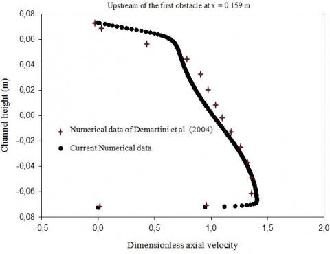
To examine the computational technique, we validated the present numerical results with those of Demartini et al. [23]. A comparison of dimensionless profiles of axial velocity at x = 0.159 m is conducted and reported in Figure 3. The plots in Figure 3 shows a good agreement between the recent analysis and those of Demartini el. [23].
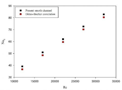
The recent analysis on thermal energy of air through a smooth rectangular conduit in the absence of deflectors is validated in terms of average Nusselt number.
Figure 3. Validation plots of dimensionless axial velocity profiles at x = 0.159 m for Uin = 7.8 m/s
Figure 4. Verification plots of the average Nusselt number for the smooth rectangular air channel
The value of Nusselt (nu0) obtained from the present smooth conduit is compared with the experimental correlation of Dittus-Boelter for turbulent flow in channels. The plots in Figure 4 presents a comparison of nu0 obtained from the recent analysis with that from correlation of Eqs. (16). the comparison shows an acceptable agreement with the exact solution values for the Nusselt number in Eq. (16).
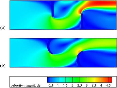
The effect of the obstacle form geometry on the mean velocity fields in the whole domain examined is shown in Figure 5. Two various forms of obstacles are considered. In the first case, a vertical flat rectangular-shaped obstacle pair (simple baffle plates or traditional obstacles) is considered (see Figure 5 (a)) and in the second one, an obstacle pair arched towards the upstream end is considered (see Figure 5 (b)]. Both the obstacle cases are simulated for Re = 12,000. The plot trends of mean velocity fields in Figure 5 are similar for both cases, flat rectangular and arc-shaped obstacles. The contour plots of speeds show the highest value in the regions between the top of the flat and arc obstacles and the channel walls, and the lowest in the areas around the obstacles. In the regions downstream, recirculation cells with very low velocities of negative values are observed. The figure also shows that in the first obstacle configuration of flat rectangular type, the length, strength, and size of recycling cells is most important and high speeds are observed in the region opposite the lower wall-mounted deflector.
Figure 6 (a) and (b) shows the numerical data of dimensionless axial velocity (u/Uin) profiles upstream of the top channel wall-mounted obstacle for axial stations x = 0.159 m and x = 0.189 m, respectively. For a constant value of the Reynolds number of 12 × 103 and for two different geometries of obstacles, the impact of the modification and the redirection in the field of air augments as the heat transfer fluid approaches the first hot upper channel wall-attached deflector, augmenting the speed of air approaching the gap under this same deflector.
Figure 5. Distribution plots of mean velocity fields for various cases at Re = 12 × 103 and (a) channel with staggered flat rectangular obstacles, (b) channel with staggered arc-shaped obstacles
The result analysis of these plots in these same figures shows that the introduction of the one of the two configurations of obstacles, simple or shaped obstacle does not affect the aerodynamic aspect of the field of air upstream of the left obstacle.
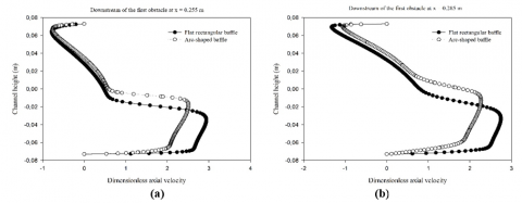
In the region between the left and the right deflectors, at transverse points x = 0.255 m and x = 0.285 m from the channel intake, respectively 0.027 m and 0.057 m behind the left hot upper wall-attached deflector, the air speed is reduced in the upper area of the conduit, while in the lower area is augmented, Figure 7. What was also noticed, the fluid dynamics in the presence of obstacles in the flat rectangular geometry accelerates more and more, from inlet to outlet, by augmenting the strength of these vortices.
Figure 6. Dimensionless profiles of axial velocity upstream of the first obstacle at (a) x = 0.159 m, and (b) x = 0.189 m, for Re = 12 × 103
Figure 7. Dimensionless profiles of axial velocity downstream of the first obstacle at (a) x = 0.255 m, and (b) x = 0.285 m, for Re = 12 × 103
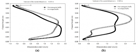
Figure 8 (a) and (b) shows the variation of dimensionless profiles of axial velocity (u/Uin) as a function of deflector geometry, flat rectangular and arc-shaped deflectors, at axial stations x = 0.315 m and x = 0.345 m, 0.087 m and 0.117 m after the left deflector, and 0.055 m and 0.025 m before the right deflector, respectively. In these same locations, the analysis of u/Uin profiles indicates that as air approaches the right insulated lower wall-mounted deflector in both configurations under consideration, flat and arc versions; its speed is decreased in the bottom region of the second lower part of the duct, while in the top region of the first part is started to accelerate toward the gap above this same second insulated deflector. For the same Reynolds number, Re = 12 × 103, the comparison of dimensionless profiles of axial velocity for both the flat and the arc-shaped deflector geometries shows that the first simple rectangular deflector forces the longest recirculation area.
Figure 8. Dimensionless profiles of axial velocity between the left and the right obstacles at (a) x = 0.315 m, and (b) x = 0.345 m, for Re = 12 × 103
Figure 9 shows the distribution of dimensionless profiles of axial velocity (u/Uin) along the conduit depth, downstream of the insulated bottom wall-placed deflector, near the outlet, at the transverse position x = 0.525 m, in the cases of simple flat rectangular and arc-shaped deflectors, when Re = 12 × 103. The maximum values of x-speed are reported on the upper part of deflector back areas, while the x-speed is observed to be very low at the reverse air flow region. The plots in this same station also show that the highest x-speeds are shown for the first deflector geometry, flat rectangular, while the lowest one is for the second configuration of arc-shape.
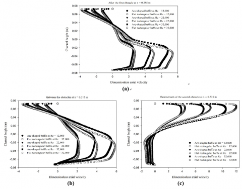
The impact of the flow rate in terms of Reynolds number on the dimensionless profiles of axial velocity, downstream of the first hot deflector at x = 0.285 m, between the left and the right deflectors at x = 0.315 m, and behind the second insulated deflector at x = 0.525 m from the conduit inlet, for two different geometries, flat rectangular and arc-shaped, is addressed in Figure 10 (a), (b), and (c), respectively, and three various values of Reynolds number are suggested, 12 × 103, 22 × 103 and 32 × 103. In these same plots, the air speed tends to augment with the range of Reynolds number from 1.2 × 10⁴ to 3.2 × 10⁴ for both the flat and arc deflector configurations under study. The numerical analysis of these same figures also shows that the deflector of flat rectangular simple model has the biggest counter-rotating vortex lengths by comparing with those of the deflector of arc geometry whatever the Reynolds number value, and that these vortices for both studied deflector configurations significantly augment as the flow rate becomes large.
Figure 9. Dimensionless profiles of axial velocity behind the second obstacle at x = 0.525 m, for Re = 12 × 103
Figure 10. Variation plots of dimensionless axial velocity profiles as a function of the Reynolds number at (a) x = 0.285 m, (b) x = 0.315 m, and (c) x = 0.525 m
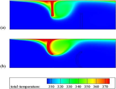
Figure 11. Distribution plots of flow temperature fields for various cases at Re = 12 × 103 and (a) channel with staggered flat rectangular obstacles, (b) channel with staggered arc-shaped obstacles
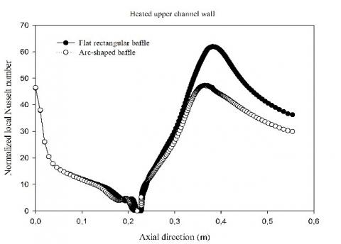
Figure 12. Variation plots of normalized local Nusselt numbers on the hot upper channel wall for various cases at Re = 12 × 103
The temperature field in the case of two various structures of deflectors, i.e., flat rectangular and arc, are reported in Figure 11 (a) and (b), respectively. The numerical results show that the temperature values of air are very high next to the upper hot surface of the channel, especially near the left face of the first fin in both treated obstacle models, as well as in the recirculation zone on the back region of this same fin. The temperature values are reduced in the regions between the edge of the deflectors and the channel walls.
The impact of each model of deflectors on the normalized values of the local Nusselt number (Nux/Nu0), along the hot top surface of the conduit, is reported in Figure 12. As shown in these plots, the highest values of Nux/Nu0 are shown next to the tip of the insulated surface-attached second deflector, due to the high speed of airflow in this region of the channel. The first deflector model in the flat rectangular simple configuration forces a considerable improvement in the Nux/Nu0 than that with the arc one under the same Reynolds number of 12 × 103, especially in the insulated second deflector regime.
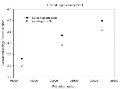
Figure 13 addresses the evolution of normalized average profiles of Nusselt number, Nu/Nu0, with the Reynolds number. In the figure, the Nu/Nu0 value is enhanced with the flow rate from 1.2 × 10⁴ to 3.2 × 10⁴, for both the considered geometries. Concerning the reported deflector geometry effect, the result analysis shows that the installation of conventional or reconfigured deflectors in the flow field made a considerable augmentation in the average Nusselt number over the smooth rectangular air conduit in the absence of deflectors. As shown in the figure and as expected, the normalized average number of Nusselt of the flat rectangular first deflector is considerably higher than that with arc model, for all values of considered Re numbers.
Figure 13. Variation plots of normalized average Nusselt numbers as a function of the Reynolds number
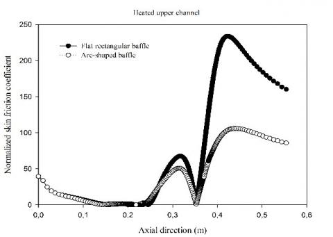
Figure 14. Variation plots of normalized local skin friction coefficients on the hot upper channel wall for various cases at Re = 12 × 103
Figure 14 presents the normalized local coefficient of skin friction, Cf/f0, along the hot bottom surface of the upper conduit wall for two different geometries of deflectors in the case of Re of value of 12 × 103. In this figure, the flat rectangular baffled conduit case provides higher frictions than that with the arc geometry deflectors for almost stations.
Figure 15 reports the mean variation in the skin friction coefficient as a function of the Reynolds number, from 12 × 103 to 32 × 103, for both the examined deflector models. The figure shows that the normalized average value of friction, f/f0, augments with augmenting the Reynolds number for all considered deflector models. The average augmentation in the skin friction coefficient in the presence of rectangular and arc deflectors is in a range of 6.103 to 25.606 times; and 3.326 to 14.148 times over the smooth rectangular air channel in the case of no deflector, respectively, depending on the Reynolds number values. This shows that the presence of the simple type deflector in the flow field leads to a substantial enhancement in skin friction in the whole domain examined.
Figure 15. Variation plots of normalized average skin friction coefficients as a function of the Reynolds number
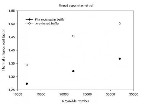
The plots of factors of the thermal enhancement (TEF) along with the Reynolds number (12 × 103 - 3.2 × 10⁴) are presented in Figure 16 for both deflector models under investigation. The TEF value tends to enhance with the range of the Reynolds number. The TEF values are all upper than 1.0, which are among 1.273 and 1.368; and 1.344 and 1.501 for flat rectangular, and arc-shaped deflectors, respectively. Over the range investigated, Re = 12 × 103 - 3.2 × 10⁴, The TEF value of arc geometry deflectors was higher than that of flat rectangular simple deflectors, which indicates that the deflector of arc geometry is more advantageous than the other simple conventional deflectors, for all Reynolds investigated.
Figure 16. Variation plots of thermal enhancement factors as a function of the Reynolds number
A study of fluid dynamics and heat transfer around flat rectangular and arc-shaped deflectors in shell-and-tube heat exchangers was reported. The Finite Volume Method (FVM) was used with the Semi-Implicit Pressure Linked Equation (SIMPLE) discretization algorithm and the Quadratic Upstream Interpolation for Convective Kinetics Differencing (QUICK) numerical scheme, in order to integrate and solve the Reynolds averaged Navier-Stokes (RANS) equations with the standard k-ε turbulence model and the energy equation. The fluid dynamic analysis shows that the deflector of arc geometry has the smallest lengths of recycling cells by comparing with those of the flat rectangular simple deflector, and that these vortices in both configurations, flat rectangular and arc, enhance significantly as the value of the Reynolds number becomes large. The TEF value of arc model deflectors was higher than that of simple flat rectangular deflectors, which shows that the deflector in the arc geometry is more advantageous than the other flat rectangular simple deflectors, for all Reynolds considered.
[1] Founti MA, Whitelaw JH. (1981). Shell side flow in a model disc and doughnut heat exchanger. Tech. Report FS/81/37, Mech. Eng. Dept., Imperial College, London, UK.
[2] Valencia A, Cid M. (2002). Turbulent unsteady flow and heat transfer in channels with periodically mounted square bars. International Journal of Heat and Mass Transfer 45(8): 1661-1673. https://doi.org/10.1016/S0017-9310(01)00267-8
[3] Dutta P, Hossain A. (2005). Internal cooling augmentation in rectangular channel using two inclined baffles. International Journal of Heat and Fluid Flow 26 (2): 223-232.
https://doi.org/10.1016/j.ijheatfluidflow.2004.08.001
[4] Nasiruddin, Kamran Siddiqui MH. (2007). Heat transfer augmentation in a heat exchanger tube using a baffle. International Journal of Heat and Fluid Flow 28(2): 318-328. https://doi.org/10.1016/j.ijheatfluidflow.2006.03.020
[5] Ozceyhan V, Gunes S, Buyukalaca O, Altuntop N. (2008). Heat transfer enhancement in a tube using circular cross sectional rings separated from wall. Applied Energy 85(10): 988-1001. https://doi.org/10.1016/j.apenergy.2008.02.007
[6] Ali M, Zeitoun O, Nuhait A. (2011). Forced convection heat transfer over horizontal triangular cylinder in cross flow. International Journal of Thermal Sciences 50(1): 106-114. https://doi.org/10.1016/j.ijthermalsci.2010.09.007
[7] Wang F, Zhang J, Wang S. (2012). Investigation on flow and heat transfer characteristics in rectangular channel with drop-shaped pin fins. Propulsion and Power Research 1(1): 64-70. https://doi.org/10.1016/j.jppr.2012.10.003
[8] Rao Y, Xu Y, Wan C. (2012). An experimental and numerical study of flow and heat transfer in channels with pin fin-dimple and pin fin arrays. Experimental Thermal and Fluid Science 38: 237-247. https://doi.org/10.1016/j.expthermflusci.2011.12.012
[9] Alam T, Saini RP, Saini JS. (2014). Experimental investigation on heat transfer enhancement due to V-shaped perforated blocks in a rectangular duct of solar air heater. Energy Conversion and Management 81: 374-383. https://doi.org/10.1016/j.enconman.2014.02.044
[10] Nanan K, Thianpong C, Pimsarn M, Chuwattanakul V, Eiamsa-ard S. (2017). Flow and thermal mechanisms in a heat exchanger tube inserted with twisted cross-baffle turbulators. Applied Thermal Engineering 114: 130-147. http://dx.doi.org/10.1016/j.applthermaleng.2016.11.153
[11] Li Z, Gao Y. (2017). Numerical study of turbulent flow and heat transfer in cross-corrugated triangular ducts with delta-shaped baffles. International Journal of Heat and Mass Transfer 108: 658-670. https://doi.org/10.1016/j.ijheatmasstransfer.2016.12.054
[12] Hosseinnezhad R, Akbari OA, Hassanzadeh Afrouzi H, Biglarian M, Koveiti A, Toghraie D. (2018). Numerical study of turbulent nanofluid heat transfer in a tubular heat exchanger with twin twisted-tape inserts. Journal of Thermal Analysis and Calorimetry 132(1): 741-759. https://doi.org/10.1007/s10973-017-6900-5
[13] Ismael MA, Mansour MA, Chamkha AJ, Rashad AM. (2016). Mixed convection in a nanofluid filled-cavity with partial slip subjected to constant heat flux and inclined magnetic field, Journal of Magnetism and Magnetic Materials 416: 25-36. https://doi.org/10.1016/j.jmmm.2016.05.006
[14] Rashad AM, Ismael MA, Chamkha AJ, Mansour MA. (2016). MHD mixed convection of localized heat source/sink in a nanofluid-filled lid-driven square cavity with partial slip. Journal of the Taiwan Institute of Chemical Engineers, 68 (2016) 173-186. https://doi.org/10.1016/j.jtice.2016.08.033
[15] Rashad AM, Rashidi MM, Lorenzini G, Ahmed SE, Aly AM. (2017). Magnetic field and internal heat generation effects on the free convection in a rectangular cavity filled with a porous medium saturated with Cu-water nanofluid. International Journal of Heat and Mass Transfer 104: 878-889. https://doi.org/10.1016/j.ijheatmasstransfer.2016.08.025
[16] Sivasankaran S, Mansour MA, Rashad AM, Bhuvaneswari M. (2016). MHD mixed convection of Cu-water nanofluid in a two-sided lid-driven porous cavity with a partial slip. Numerical Heat Transfer, Part A: Applications 70(12): 1356-1370. https://doi.org/10.1080/10407782.2016.1243957
[17] Ahmadi MH, Ramezanizadeh M, Nazari MA, Lorenzini G, R Kumar, Jilte R. (2018). Applications of nanofluids in geothermal: a review. Mathematical Modelling of Engineering Problems 5(4): 281-285. https://doi.org/10.18280/mmep.050402
[18] Vasanthakumari R, Pondy P. (2018). Mixed convection of silver and titanium dioxide nanofluids along inclined stretching sheet in presence of MHD with heat generation and suction effect. Mathematical Modelling of Engineering Problems 5(2): 123-129. https://doi.org/10.18280/mmep.050210
[19] Tahmasebi A, Mahdavi M, Ghalambaz M. (2018). Local thermal nonequilibrium conjugate natural convection heat transfer of nanofluids in a cavity partially filled with porous media using Buongiorno’s model. Numerical Heat Transfer, Part A: Applications 73(4): 254-276. https://doi.org/10.1080/10407782.2017.1422632
[20] Mehryan SAM, Ghalambaz M, Izadi M. (2019). Conjugate natural convection of nanofluids inside an enclosure filled by three layers of solid, porous medium and free nanofluid using Buongiorno’s and local thermal non-equilibrium models. Journal of Thermal Analysis and Calorimetry 135(2): 1047-1067. https://doi.org/10.1007/s10973-018-7380-y
[21] Mehryan SAM, Izadpanahi E, Ghalambaz M, Chamkha AJ. (2019). Mixed convection flow caused by an oscillating cylinder in a square cavity filled with Cu-Al2O3/water hybrid nanofluid. Journal of Thermal Analysis and Calorimetry, 1-18. https://doi.org/10.1007/s10973-019-08012-2
[22] Mehryan SAM, Kashkooli FM, Ghalambaz M, Chamkha AJ. (2017). Free convection of hybrid Al2O3-Cu water nanofluid in a differentially heated porous cavity. Advanced Powder Technology 28(9): 2295-2305. https://doi.org/10.1016/j.apt.2017.06.011
[23] Demartini LC, Vielmo HA, Möller SV. (2004). Numeric and experimental analysis of the turbulent flow through a channel with baffle plates. Journal of the Brazilian Society of Mechanical Sciences and Engineering 26(2): 153-159.
[24] Ghalambaz M, Doostani A, Izadpanahi E, Chamkha AJ. (2017). Phase-change heat transfer in a cavity heated from below: The effect of utilizing single or hybrid nanoparticles as additives. Journal of the Taiwan Institute of Chemical Engineers 72: 104-115. https://doi.org/10.1016/j.jtice.2017.01.010
[25] Ghalambaz M, Doostani A, Chamkha AJ, Ismael MA. (2017). Melting of Nanoparticles-Enhanced Phase-Change Materials in an Enclosure: Effect of Hybrid Nanoparticles. International Journal of Mechanical Sciences 134: 85-97. https://doi.org/10.1016/j.ijmecsci.2017.09.045
[26] Ghalambaz M, Jamesahar E, Ismael MA, Chamkha AJ. (2017). Fluid-structure interaction study of natural convection heat transfer over a flexible oscillating fin in a square cavity. International Journal of Thermal Sciences 111: 256-273. https://doi.org/10.1016/j.ijthermalsci.2016.09.001
[27] Chamkha AJ, Doostanidezfuli A, Izadpanahi E, Ghalambaz M. (2017). Phase-change heat transfer of single/hybrid nanoparticles-enhanced phase-change materials over a heated horizontal cylinder confined in a square cavity. Advanced Powder Technology 28(2): 385-397. https://doi.org/10.1016/j.apt.2016.10.009
[28] Launder BE, Spalding DB. (1974). The numerical computation of turbulent flows. Computer Methods in Applied Mechanics and Engineering 3: 269-289.
[29] Leonard BP, Mokhtari S. (1990). Ultra-Sharp Nonoscillatory convection schemes for high-speed steady multidimensional flow. NASA TM 1-2568, NASA Lewis Research Center.
[30] Patankar SV. (1980). Numerical heat transfer and fluid flow. McGraw-Hill, New York.