Muhammet Emin Sahin* | Hasan Guler | Serdar Ethem Hamamci
© 2020 IIETA. This article is published by IIETA and is licensed under the CC BY 4.0 license (http://creativecommons.org/licenses/by/4.0/).
OPEN ACCESS
In this study, a memristor based hyperchaotic circuit is presented and implemented for communication systems on FPGA platform. Four dimensional hyperchaotic system, which contains active flux controlled memristor is designed by using a smooth continuous nonlinearity. Dynamical characteristics of designed hyperchaotic circuit are examined such as equilibrium points, chaotic attractors, Lyapunov exponents and bifurcation diagram. Furthermore, an electronic circuit model of hyperchaotic system has been modeled and results are submitted. Chaotic circuits are used in communication systems especially in secure communication due to their sensitive dependence on the initial conditions, not periodic, and having a spread spectrum. By using nonlinearity of memristor, the signals obtained from memristor based hyperchaotic system have been realized to analog and digital communication schemes on FPGA platform, which is suitable for re-programmable and reconfigurable systems. The success of memristor based hyperchaotic circuit with FPGA based communication is demonstrated by both simulation and experimental results.
chaos, circuit implementation, communication systems, FPGA, memristor, optimization
After Leon O. Chua introduced the memristor in 1971 and the HP team submitted the first physical memristor to the literature, studies on the memristor have been rapidly increasing [1, 2]. The memristor described by flux and charge is considered to be the fourth basic circuit element [1]. The memristor has brought a completely new field of development in various interdisciplinary fields. In particular, many researchers have begun to benefit from memristor based application circuits due to the unique characteristics of memristor over the last few years [3-6].
In order to construct various new memristor based chaotic circuits, the memristor element is integrated into some existing linear or nonlinear electronic circuits. The use of chaotic dynamics is important in many areas and there is increasing interest particularly in engineering applications that aim to create effective chaos through simple physical systems such as electronic circuits [7-9]. Due to the nonlinear property of the memristor element [1], a chaotic signal can easily be obtained from chaotic circuits based on memristor, which increases the interest of researchers to use memristor in the design of chaotic circuits [10-13]. However, due to technical disadvantages and the high costs of manufacturing nanoscale devices, memristor design is realized with the help of emulators. Chaotic signals which are used as a carrier in spreading spectrum communication systems are obtained with simple circuits and it is easy to do as hardware and provides an advantage in information security because chaos contains non-periodic signals. As a model for practical application, it is much more important to produce a hyperchaotic signal with more complex dynamics when comparing with chaotic signals. It is more advantageous than other systems because it has a complex structure, higher unpredictability, and more random features. The designed hyperchaotic system can be used to enhance the reliability of the secure communication system. In this respect, new hyperchaotic circuits are crucial [14]. After the discovery of the hyperchaotic Rössler system presented by Rössler, many hyperchaotic systems have been developed and presented to the literature [15]. It is used in many areas of nonlinear sciences such as secure communication, neural network, image processing, laser physics, and nonlinear circuits [16-19].
Chaotic and hyperchaotic systems are widely used for realizing analog and digital communication modulation techniques. A study by Pecora-Carroll in 1990, which showed that chaotic communication systems can be synchronized, paved the way for the use of chaotic signals in spread spectrum communication systems [20]. Chaos based analog communication systems are well affected by noise in real-time applications, despite their good performance in noiseless environments. Chaos based digital communication systems are less affected by noise than analog communication and therefore digital modulation techniques are preferred [21]. Many studies have been performed in the literature by using digital modulation techniques. Chaos shift keying (CSK) [22], chaotic on-off keying (COOK) [23] and differential chaos shift keying DCSK [24] show digital modulation techniques.
Chaotic circuit models are diversified to increase and expand chaos based engineering applications. Chaotic applications designed on an FPGA (Field Programmable Gate Array) environment have more flexible structures in which parameter changes of a chaotic system can be made easily. By changing the parameters of the designed system, the dynamic behavior of the system can be easily changed. Therefore, the realization of chaotic signal generators based on an integrated digital platform such as FPGA enables us to take advantage of these features [25]. Because of their high speed and capacity, FPGA chips have an important potential to improve information security capacity, especially in applications such as cryptology and secure communications requiring high performance and processing power [26]. Studies on digital FPGA based modeling of chaotic oscillators are of great importance in the literature [26-28]. Memristor based applications have also been studied on FPGA platform [29, 30].
In this study, a hyperchaotic circuit based on memristor is designed. Especially considering the importance of newly designed hyperchaotic circuits in communication systems, dynamic analysis of the designed system is presented and real-time implementation is performed. For chaotic communication and especially secure communication system, the signals obtained from this hyperchaotic circuit are modeled on the FPGA platform in communication systems. FPGA has made it possible to complete the work in the chaos area faster and to make it easier to develop new methods. The communication application of the designed chaotic systems is synthesized by using Xilinx Spartan-3E family XC3S500E board. Synchronization of hyperchaotic circuits obtained from the designed system is very important for a good signal transmission in the analog communication system. In order to solve the synchronization problem of this model, system gains are obtained by using a PID control scheme based on the Firefly algorithm. Using the algorithm, optimal control gains are achieved in PID controller gains. Moreover, as an application, the proposed system is implemented on the FPGA platform to a chaotic communication system. Likewise, COOK modulation, which is one of the digital communication methods, is realized in the FPGA platform and presented to the literature. BER performances of FPGA applications of memristor based hyperchaotic generators are submitted. The success of memristor based hyperchaotic circuit with FPGA based communication is demonstrated by both simulation and experimental results.
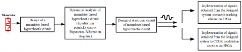
This paper is arranged as follows. First, the model of the hyperchaotic circuit based on memristor is designed in Sect. 2. Then, in order to examine dynamical characteristics; the equilibrium points, Lyapunov exponents, and bifurcation diagrams are given in Sect. 3. Next, Chaotic communication schemes for analog and digital modulation systems are modeled for memristor based hyperchaotic circuit in Sect. 4. After that, applications of these modulations systems on FPGA are given in Sect. 5. Finally, the results are submitted in Sect. 6. Block diagram of paper organized is given in Figure 1.
Figure 1. Block diagram of paper organized
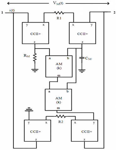
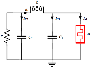
The memristor represents a nonlinear relationship between charge q and flux φ. A characteristic memristor emulator is designed to perform a voltage controlled memristor as shown in Figure 2 and memristor based hyperchaotic circuit is modeled by using memristor emulator with a smooth continuous nonlinearity [10, 31-33].
The used memristor emulator's fundamental relationship for designing memristor based hyperchaotic circuit can be given by Cam and Sedef [31] and Sahin et al. [33]. If the circuit in Figure 2 is analyzed by using the definition relations of circuit elements, the voltage on the CM capacitor can be expressed as $v_{C M}=q_{C M} / C_{M}$. In addition, provided that $q_{0}$ is the initial value, it is expressed as $q_{C M}(t)=\int_{0}^{t} i_{C M}(\tau) d \tau+q_{0}$ . If this equation is expressed in terms of voltage, it will be $\left(i_{C M}=-\frac{V_{M}}{R_{1}}\right)$ , $q_{C M}(t)=-\frac{1}{R_{1}} \int_{0}^{t} v_{M}(\tau) d \tau+q_{0}$. The memristor is developed for cubic form and schematic of memristor based hyperchaotic shown in Figure 3, the form emulator equations are given following, (for more details, the study [33] can be examined).
$M(t)=\pm \text{ }\frac{{{R}_{1}}{{R}_{2}}}{{{k}^{2}}{{R}_{M}}{{v}_{CM}}{{(t)}^{2}}}$ (1)
${{i}_{M}}=\frac{{{k}^{2}}{{R}_{M}}{{v}_{M}}(t){{v}_{CM}}{{(t)}^{2}}}{{{R}_{1}}{{R}_{2}}}$ (2)
${{\dot{v}}_{CM}}(t)=-\frac{1}{{{R}_{1}}{{C}_{M}}}{{v}_{M}}(t)$ (3)
When the system is designed by using Kirchhoff laws, the state equations of the system are as follows:
$\begin{align} & {{{\dot{v}}}_{C1}}(t)=\frac{{{i}_{L}}(t)}{{{C}_{1}}}-\frac{{{i}_{M}}(t)}{{{C}_{1}}} & {{{\dot{v}}}_{C2}}(t)=\frac{{{v}_{C2}}(t)}{R{{C}_{2}}}-\frac{{{i}_{L}}(t)}{{{C}_{2}}} \\ & {{{\dot{i}}}_{L}}(t)=\frac{{{v}_{C2}}(t)}{L}-\frac{{{v}_{C1}}(t)}{L} & {{{\dot{v}}}_{CM}}(t)=-\frac{1}{{{R}_{1}}{{C}_{M}}}{{v}_{C1}}(t) \\\end{align}$ (4)
When Eq. (4) is arranged by using Eqns. (2) and (3) of memristor emulator, in the state equations, x, y, z, u are the states and a, b, c, d, n, m0 and m1 are parameters. When Eq. (4) is redefined according to $V_{C 1}=x, V_{C 2}=y, i_{L}=z, V_{C M}=u$, $a=\frac{1}{C_{1}}, b=\frac{1}{C_{2}}, c=\frac{1}{L}, d=\frac{1}{R}, n=-1 / R_{1} C_{M}$:
$\begin{align} & \dot{x}=az-ax({{m}_{0}}+{{m}_{1}}{{u}^{2}}) \\ & \dot{y}=bdy-bz \\ & \dot{z}=cy-cx \\ & \dot{u}=nx \\\end{align}$ (5)
Figure 2. Design of memristor emulator circuit
Figure 3. Schematic of memristor based hyperchaotic circuit
The basic dynamics of the hyperchaotic system are analyzed in this section. Some of the analysis methods: equilibrium points, phase portraits, Lyapunov exponents and bifurcation diagrams of the system are examined and results are given about the designed system. Numerical analysis are performed in MATLAB to confirm the analytical estimates obtained in the previous section.
3.1 Chaotic attractor
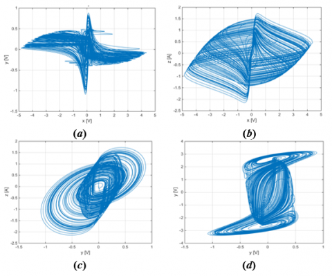
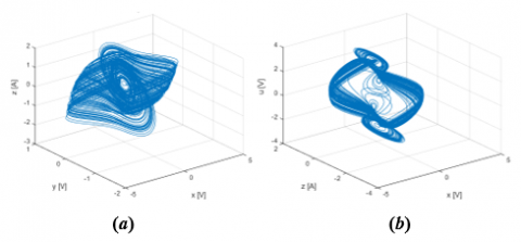
The attractors are a set of points or dots showing possible stable states of a system in the phase space. MATLAB Runge Kutta “ode.m” algorithm is utilized to draw phase portraits. By using Eq. (5), results of this system are obtained. Chaotic attractors are given in Figure 4 when parameters of a=7, b=1, c=2.5, d=1, m0=-1.2, m1=1 and n=-6, initial conditions x(0)=0.1, y(0)=0, z(0)=0 and u(0)=0 are fixed these values. Three dimensional graphs of attractors of memristor based hyperchaotic circuit is shown Figure 5.
Figure 4. Chaotic attractors of memristor based hyperchaotic circuit (a) x-y (b) x-z (a) y-z (b) y-u
Figure 5. Three dimensional graphs of attractors of memristor based hyperchaotic circuit (a) x-y-z and (b) x-z-u
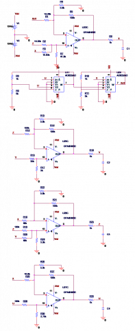
When the numerical simulation results obtained from the designed memristor based hyperchaotic circuit are examined, it is observed that the numerical range of each variable parameter varies between nearly −5V and + 5V. The electronic circuit of the designed hyperchaotic system in Eq. (5) is modeled in the OrCAD-PSpice circuit design program, which is given in Figure 6. An electronic model of system which is experimentally established in a laboratory environment is submitted. The components values are given in Table 1. Real time results are observed with the help of oscilloscope which is illustrated in Figure 7. The real time results of this system are consistent with the MATLAB simulation results.
Figure 6. The electronic circuits of the memristor based hyperchaotic system
Table 1. Components of memristor based hyperchaotic circuit
|
Source |
Value |
Source |
Value |
|
AM |
AD633JN |
R8=R11 |
9 kΩ |
|
Opamp |
OPA404/TL084 |
R13 |
50 kΩ |
|
R1=R2 |
14.28 kΩ |
R17 |
5 kΩ |
|
R3 |
10.63 kΩ |
R18=R20 |
40 kΩ |
|
R4=R15=R22=R24 |
5.6 kΩ |
R25 |
16.6 kΩ |
|
R5=R12=R14=R19=R21=R26=R27 |
100 kΩ |
R28 |
3.3 kΩ |
|
R6=R9=R10=R16=R23=R29 R7 |
1 kΩ 41.7 kΩ |
R30 C1=C2=C3=C4 Vs |
2.75 kΩ 1nF-100 nF ± 15 V |
Figure 7. Experimental chaotic attractors (a) x-y (b) x-z (c) y-z (d) y-u
3.2 Equilibrium points
Behaviors around equilibrium points are important for explaining the stability of the system. If the orbits around the equilibrium points converge to these points, the system is asymptotically stable. If it diverges, the system is unstable. The system is stable in an orbit around the equilibrium point, unless asymptotically unstable. Designed memristor based hyperchaotic circuit’s state equations are equaled to zero and this is given Eq. (6) when the parameters are used as a=7, b=1, c=2.5, d=1, e=3.75, f=3, n=-6, m0=-1.2 and m1=1, initial conditions x(0)=0.1, y(0)=0, z(0)=0 and u(0)=0.
$\begin{align} & 0=az-ax({{m}_{0}}+{{m}_{1}}{{u}^{2}}) \\ & 0=bdy-bz \\ & 0=cy-cx \\ & 0=nx \\\end{align}$ (6)
Equations are set to zero and solved as shown above to find the solution of equilibrium points E= (E1, E2, E3, E4) of the designed system. If the expressions found in the solution of the equations are real numbers, it can be said that the system has equilibrium points. By examining the eigenvalues obtained using equilibrium points, comments can be made about the equilibrium point. The equilibrium points are asymptotically stable if the real eigenvalues (or real parts of complex eigenvalues) are negative. Stable nodes and stable focus are given as examples of such equilibrium positions. The corresponding equilibrium point is unstable if the real part of at least one eigenvalue is positive such as a saddle. If the system has purely imaginary roots, equilibrium point is a center. For this system, E= (0, 0, 0, $\rho$) equilibrium points are given and ( $\rho=1.261$) can be used. After finding the equilibrium points, the Jacobian matrix is created and analyzed according to the equilibrium points of the system.
$Jac(x,y,z,u)=\left( \begin{matrix} -a{{m}_{0}}-a{{m}_{1}}{{u}^{2}} & 0 & a & -2a{{m}_{1}}ux \\ 0 & bd & -b & 0 \\ -c & c & 0 & 0 \\ n & 0 & 0 & 0 \\\end{matrix} \right)$ (7)
The characteristic equation of is shown by,
$\det (\lambda I-J)=0$ (8)
Eq. (6) is solved and roots are λ1= 0, λ2= -1.152+4.15i, λ3= -1.152-4.15i and λ4=0.574. The eigenvalues found in order to express the stability or instability of the system are examined. If at least one of the eigenvalues obtained should have positive, the system is unstable. Since λ4 meets this requirement for the designed system, the system is chaotic.
3.3 Lyapunov exponents
The Lyapunov exponents method is a mathematical analysis method that shows whether the time series of the system has chaotic components. In addition, this method shows the numerical expression of the sensitivity to initial conditions, one of the most important features of chaotic systems and the Lyapunov exponent is represented by L [34]. L1=0.31, L2=0.0097, L3=-0.0098 and L4=-30.21 are obtained when the parameters are fixed as specified (a=7, b=1, c=2.5, d=1, m0=-1.2, m1=1 and n=-6) and this system is started to run for initial conditions (0.1, 0, 0, 0). To mention the chaotic of a system, the system must have at least one positive Lyapunov exponent. Lyapunov graph of the designed memristor based hyperchaotic circuit is shown in Figure 8.
${{D}_{L}}=j+\frac{\sum\nolimits_{i}^{j}{{{L}_{i}}}}{{{L}_{j+1}}}=3.01$ (9)
As can be seen, two of the Lyapunov exponents in Figure 8 has a positive value. This is a necessary condition to be hyperchaotic. The system maintains positive Lyapunov exponents values even if the time is increased. Therefore, it is said that the designed circuit is a hyperchaotic system [35].
Figure 8. Dynamics of Lyapunov exponent
3.4 Bifurcation diagram
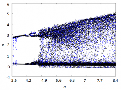
Bifurcation can be defined as small changes in the parameters affecting the behavior of the system in dynamic systems, causing sudden changes in the equilibrium of the system. While the bifurcation diagram is obtained, the differential equation system in Eq. (5) is solved with on MATLAB software and bifurcation diagram is given in Figure 9.
Figure 9. Bifurcation diagram of memristor based hyperchaotic circuit (for “a” parameter)
The results of the orbits are expressed in different colors shown for different initial conditions such as black (0.1, 0, 0, 0) and blue (0.1, 0, 0.01, 1) in Figure 9. These colors provide some information in bifurcation schemes. The initial conditions of the system for the parameter is selected in the range of 3.5 to 8.4, with the other parameters remaining constant. It can be seen from the figure that the circuit will show periodic behavior for aÎ(3.5-4.1), quasi-periodic behavior for aÎ(4.2-4.6) and chaotic behavior for aÎ(4.3-8.4). Bifurcation analysis given above has been obtained by applying some dynamic properties to the designed system.
4.1 Chaotic masking
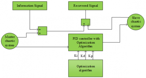
When the studies are examined, one of the methods used in the chaos based secure communication systems is the chaotic masking method. The idea of transmitting and encrypting data using chaos in communication systems emerged in 1990. It has been shown by Pecora and Carroll that synchronization is possible in two different chaotic oscillators [36]. The first study on communication is chaotic masking. In 1993, Cuomo and Oppenheim [7, 37] established and demonstrated a secure communication system using the Lorenz equation system. These studies are important in terms of being the first application in chaotic communication system design, since they show how synchronization concept can be used in masking the information sign by adding chaotic signals to an information signal. Synchronization ensures that two or more systems with different chaotic behavior show the same chaotic behavior. Due to the importance of the synchronization concept in the receiver circuit, PID controls have been preferred to ensure synchronization of chaotic circuits operated with different initial conditions. The optimization method is preferred in obtaining the gain coefficients of the PID controller. PID gain coefficients are obtained by using the Firefly algorithm. Blocks diagram of synchronization chaotic system is given Figure 10.
In order to make numerical designs of differential equations, it is necessary to make the equations independent of time. There are many discretization methods in the literature. These methods have advantages and disadvantages compared to each other. For example, while one method uses less hardware than the other does, the same method can discriminate with a higher margin of error than the other can. Due to the circuit structure used in this study, the margin of error should be within the appropriate limits. Since the design of chaotic behavior on a digital platform is obtained, less resource usage makes the chosen method even more important [38, 39]. For this reason, Euler method is chosen as the discretization method. Comparison of discretization methods is illustrated in Table 2.
The state equations of the memristor based hyperchaotic circuit model are converted to the following discrete time equations with a step interval of T= 1e-3. Euler method is given Eq. (10).
$x[n+1]=x[n]+Ty[n]$ (10)
Discrete master circuit:
$\begin{align} & {{x}_{m1}}[n+1]=T(a{{x}_{m3}}[n]-a{{x}_{m1}}[n]{{m}_{0}}-a{{m}_{1}}{{x}_{m1}}[n]{{x}_{m4}}{{[n]}^{2}})+{{x}_{m1}}[n] \\ & {{x}_{m2}}[n+1]=T(b(d{{x}_{m2}}[n]-{{x}_{m3}}[n]))+{{x}_{m2}}[n] \\ & {{x}_{m3}}[n+1]=T(-c({{x}_{m1}}[n]-{{x}_{m2}}[n]))+{{x}_{m3}}[n] \\ & {{x}_{m4}}[n+1]=T(n{{x}_{m1}}[n])+{{x}_{m4}}[n] \\\end{align}$ (11)
Discrete slave circuit:
$\begin{align} & {{x}_{s1}}[n+1]=T(a{{x}_{s3}}[n]-a{{x}_{s1}}[n]{{m}_{0}}-a{{m}_{1}}{{x}_{s1}}[n]{{x}_{s4}}{{[n]}^{2}})+{{x}_{s1}}[n] \\ & {{x}_{s2}}[n+1]=T(b(d{{x}_{s3}}[n]-{{x}_{s2}}[n]))+{{x}_{s2}}[n] \\ & {{x}_{s3}}[n+1]=T(-c({{x}_{s1}}[n]-{{x}_{s2}}[n]))+{{x}_{s3}}[n] \\ & {{x}_{s4}}[n+1]=T(n{{x}_{s1}}[n])+{{x}_{s4}}[n] \\\end{align}$ (12)
Figure 10. Blocks diagram of synchronization chaotic system
Table 2. Comparison of discretization methods
|
|
Euler’s Method |
Taylor Series Method |
Runge-Kutta Methods |
|
Advantages |
1. Simple and direct 2. This method can be used for nonlinear IVPs |
1. One step, explicit 2. This method can be high order 3. Easy to show that global error is the same order as LTE. |
1. One step method 2. Global error is of the same order as local error. 3. Don’t need to know derivatives of f. 4. Easy for “Automatic Error Control”. |
|
Disadvantages |
It is less accurate and numerically unstable. Usually applicable to explicit differential equations. |
Needs the explicit form of derivatives of f. Truncation error tends to grow rapidly away from expansion point. |
They require significantly more computer time than multi-step methods of comparable accuracy, and they do not easily yield good global estimates of the truncation error. |
Error:
$\begin{align} & {{e}_{1}}[n]={{x}_{_{m1}}}[n]-{{x}_{_{s1}}}[n] \\ & {{e}_{2}}[n]={{x}_{_{m2}}}[n]-{{x}_{_{s2}}}[n] \\ & {{e}_{3}}[n]={{x}_{_{m3}}}[n]-{{x}_{_{s3}}}[n] \\ & {{e}_{4}}[n]={{x}_{_{m4}}}[n]-{{x}_{_{s4}}}[n] \\\end{align}$ (13)
The discrete PID control input is,
$c[n+1]={{K}_{p}}e+{{K}_{i}}({{I}_{n-1}}+edt)+{{K}_{d}}\frac{e-{{e}_{n-1}}}{dt}$ (14)
4.2 COOK modulation
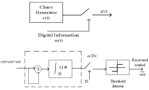
In this part, memristor based hyperchaotic circuit is implemented to digital communication by using COOK modulation. There is no need for synchronization here, which allows the transmitter to spend less energy. COOK modulation is a special case of CSK that does not require a carrier based on bit energy estimation. This communication system requires only one chaotic signal. When the “+1” symbol is transmitted, “-1” symbol is displayed with zero transmission. The modulation process can be thought of as turning the chaotic generator on and off. Demodulation can be carried out using a simple bit energy estimator as in a carrier free structure [40]. The block diagram of COOK modulator and demodulator is shown in Figure 11.
$s(t)=\left\{ \begin{matrix} c(t), & for & 1 \\ 0, & for & 0 \\\end{matrix} \right.$ (15)
Figure 11. Block diagram of COOK modulator and demodulator
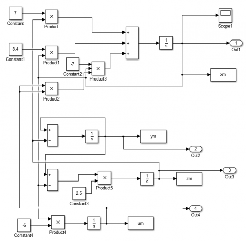
Figure 12. Block diagram of a memristor based hyperchaotic circuit
Figure 13. Block diagram of COOK modulation on MATLAB&Simulink for memristor based hyperchaotic circuit
The modulated signal from the COOK modulator circuit is transmitted via the communication channel s(t) to the demodulator circuit on the receiving side as shown in Figure 11. In the demodulator circuit, the noise added to the modulated signal in the transmission channel is collected together with n(t). This signal is then multiplied by r(t) to be integrated (correlator unit) and transmitted to the threshold detector. The signal obtained from the correlation comes to the threshold detector and the information signal is obtained according to the threshold level determined in this part [41].
The signal from the correlator is transmitted to the threshold detector. Information is obtained according to the threshold level specified in this section. The threshold value in the decision circuit is important for the success of COOK modulation. This value changes depending on the noise. This is a disadvantage of COOK modulation [41, 42].
The signals, which are obtained from memristor based hyperchaotic circuit, are used in COOK modulation on MATLAB. Figure 12 shows a block diagram of a memristor based hyperchaotic circuit. In the COOK modulation of this signal, the communication block diagram under AWGN channel is given in Figure 13. In the communication application of the system designed in MATLAB environment 4000 bits are sent, the bit duration is selected as $T_{b}=0.01$ and delay time as $T_{b}=0.5$.
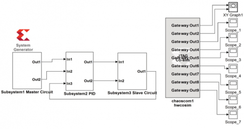
Due to the characteristics of FPGA, chips such as being numerical and reprogrammable, parameter changes of the system can be performed easily in chaotic system based FPGA applications. In addition, with the change of system parameters, the change in the dynamic behavior of the system can easily be seen. Compared to analog circuit oscillators, the fact that FPGA is fast, reliable and easy to design. This has made it possible to complete the work in the chaos area faster and to make it easier to develop new methods. Xilinx System Generator (XSG) is a high level MATLAB&Simulink based software platform that is used to quickly and easily design. Xilinx FPGA cards, perform hardware based simulation and perform real-time applications on the board [43]. XSG has a library based blocks in MATLAB&Simulink for arithmetic and logic applications, memory applications and Digital Signal Processing (DSP) applications. The only difference between XSG blocks and general Simulink blocks is that XSG blocks are used in discrete time and fixed point number format. The communication application of the designed chaotic systems is synthesized by using Xilinx Spartan-3E family XC3S500E board.
Figure 14. Block diagram of communication system on FPGA
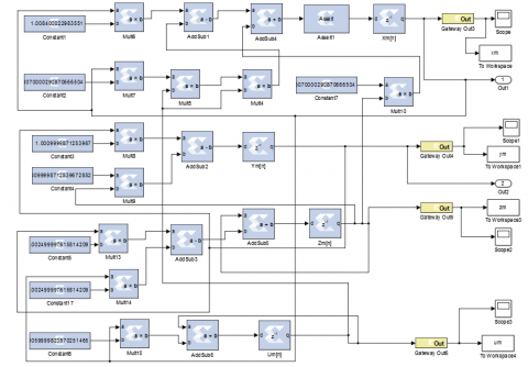
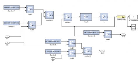
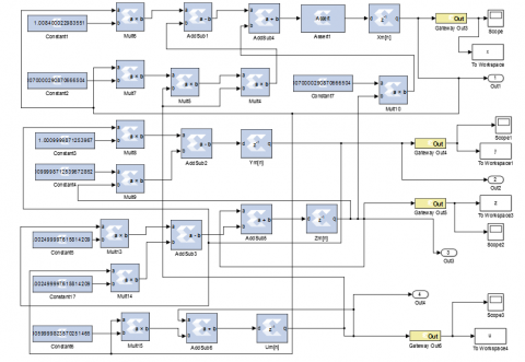
Figure 15. Block diagram of subsystem for memristor based hyperchaotic master circuit
Figure 16. Block diagram of subsystem for memristor based hyperchaotic slave circuit
Figure 17. Block diagram of subsystem for PID controller
5.1 Chaotic masking
The application of the hyperchaotic circuit designed in this section to the communication systems is realized by using analog modulation technique. The discretized equations in the previous section are modeled in XSG in FPGA environment. The designed system is modeled using Xilinx ISE Design Tools 14.5 simulation program.
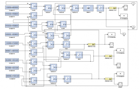
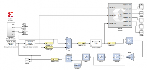
Figure 14 shows the design of the whole system on FPGA. As shown in Figure 14, the system consists of three subsystems, which include model of master, slave and PID controller circuits. The block diagram of master, slave circuits and PID control are given Figures 15, 16 and 17, respectively. The different initial conditions are master circuit [0.1, 0, 0, 0] and slave circuit [0, 0, 0, 0]. After the synchronized chaotic system is designed in MATLAB&Simulink environment, it will be sent to FPGA by the hardware cosimulation method and real time outputs will be observed in MATLAB&Simulink environment. The PID controller gain coefficients are obtained from the Firefly algorithm used for optimization, which are $K_{p}=7.79, K_{i}=416.21$ and $K_{d}=529.3$ as obtained in the previous study [33]. The parameter values used in the Firefly algorithm are selected as 20 for iterations and 50 for the population number. The algorithm performs the simulation for 100 seconds. The sum of the absolute error is obtained from the samples in the last 4 seconds as 8.2e-28.
Figure 18. Chaotic attractors of memristor based hyperchaotic circuit (a) x-y (b) y–z on FPGA
The phase portraits of the chaotic circuits designed on the FPGA platform are shown in Figure 18 in the form of x-y and y-z. Figure 19 shows the synchronization of the signal u[n] used as a carrier after it has been obtained under different initial conditions for the master and slave circuit. Chaotic signals of master circuit and slave circuit unsynchronized without PID controller is given in Figure 20. As shown in the figure, when synchronization is not performed, the master and slave signals are different from each other for different initial conditions. A good transmission of information cannot be achieved in this way.
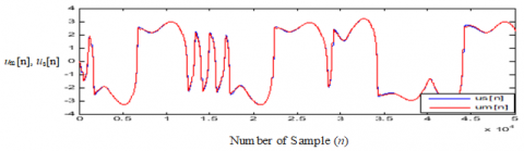
Figure 19. Chaotic signals of master circuit and slave circuit synchronized with PID controller (um[n], us[n]-Number of sample (n))
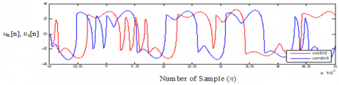
Figure 20. Hyperchaotic signals of master circuit and slave circuit unsynchronized without PID controller (us[n]-Number of sample (n))
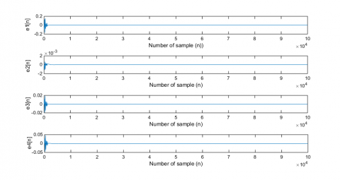
The difference between the master and slave circuits synchronized with the help of PID controls shown in Figure 21 is equalized to zero in a short time. Error waveforms of the master and slave systems obtained after synchronizing using the algorithm are shown in Figure 21. When state errors of the synchronization system (e1, e2, e3, e4) are analyzed, it is observed that the hyperchaotic system is synchronized in a short time and the amount of exceedance is low.
Figure 21. Error waveforms between synchronized master and slave system
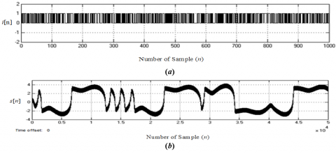
Figure 22. (a) The information signal i[n] (b) The transmitted signal s[n]
Figure 23. (a) The recovered signal i[n] (b) The hyperchaotic signal us[n]
Table 3. Final mapping report for memristor based hyperchaotic circuit with chaotic masking on FPGA
|
Resource |
Utilization |
|
Slice register |
343 |
|
LUTs |
640 |
|
Flip-Flop |
287 |
|
Bonded IOBs |
289 |
|
BUFG/BUFGCTRL/BUFHCEs |
1 |
|
DSP4831s |
68 |
|
Multiplier |
26 |
|
Adder/Subtractor |
18 |
A simple communication application is realized in FPGA environment by using the signal obtained from the synchronized circuit. In the chaotic masking technique, the information signal i[n] added to the carrier hyperchaotic signal um[n] is used in the communication system as s[n] signal on the receiving side. In Figure 22 (a) and (b), the information signal and the transmitted signal are shown, respectively. By subtracting the reproduced hyperchaotic signal from the incoming signal, the analog information signal is obtained and the transmitted information signal is obtained with very little error. The hyperchaotic signal us[n] and the recovered information signal i[n] used on the receiver side is shown in Figure 23. In order to achieve synchronization in chaotic masking, the power and amplitude of the information signal to be added must be considerably lower than the hyperchaotic carrier [44]. The number of processing blocks used in the design for the hyperchaotic circuit model and the resource utilization on the hardware are given in Table 3.
Figure 24. Block diagram of COOK modulation on FPGA
Figure 25. Block diagram of hyperchaotic circuit on FPGA
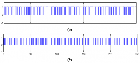
Figure 26. (a) Information signal (b) Recovered signal obtained from the COOK modulation
5.2 COOK modulation
Chaos based analog communication systems provide good performance in noise free environments, but are highly affected by noise in practice. Chaos based digital communication systems are less affected by noise than analog communication [26]. In this section, COOK modulation, one of the chaos based digital modulation techniques used in chaotic communication systems, is implemented.
In the previous section, the COOK model designed in MATLAB environment is remodeled on ISE XSG platform in order to realize it in FPGA environment. The blocks required for this system design are designed in COOK model using XSG and implemented in FPGA hardware.
Figures 24 and 25 show the COOK modulation model and the subsystem of the hyperchaotic signal used in the FPGA environment, respectively. The initial conditions are fixed for hyperchaotic circuit as [0.1, 0, 0, 0]. The design of the hyperchaotic system is designed using the required blocks in XSG in the form given in Eq. (11). In Figure 26(a) and (b) show the information signal and recovered signal obtained from the COOK modulation. The number of processing blocks used in the design for the hyperchaotic circuit model and the resource utilization on the hardware are given in Table 4.
Table 4. Final mapping report for memristor based hyperchaotic circuit with COOK modulation on FPGA
|
Resource |
Utilization |
|
Slice register |
214 |
|
LUTs |
294 |
|
Flip-Flop |
175 |
|
Bonded IOBs |
227 |
|
DSP4831s |
34 |
|
BUFG/BUFGCTRL/BUFHCEs |
1 |
|
Multiplier |
11 |
|
Adder/Subtractor |
7 |
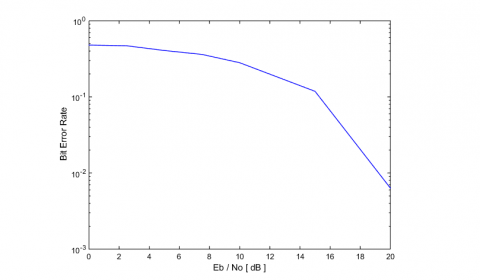
The performance of the designed communication system is analyzed under AWGN (Additive White Gaussian Noise) channel model with $E_{b} / N_{0}$ (Bit energy level/noise power spectral density) values between 0 dB and 20 dB. As can be seen in Figure 27, the transmitted bits also depend on the noise of the AWGN, very few errors occur in the realized system. Figure 27 shows BER (Bit Error Rate) performance graph for different $E_{b} / N_{0}$ values obtained by MATLAB&Simulink, which is realized by using the FPGA based design method with memristor based hyperchaotic circuit.
Figure 27. BER graph of memristor based hyperchaotic circuit
In this study, a hyperchaotic circuit model and its application to communication systems according to analog and digital modulation techniques are realized in hardware on FPGA platform. The chaotic analysis of the memristor based hyperchaotic circuit designed with the memristor emulator is performed and the results of the system are presented in real-time. As a result of the hyperchaotic analysis performed, it is confirmed by numerical results that the system is a hyperchaotic system. An electronic circuit model of the designed system is submitted. Thanks to the digital structure of the FPGA, it is observed that the real-time results confirm the simulation results. Furthermore, when using FPGA to produce chaotic signals, it is observed that FPGA is easy, fast, and reliable.
In order to use hyperchaotic circuits for communication systems, synchronization in analog modulation schemes is important. Based on the optimization algorithms, the PID control system is designed to synchronize the two hyperchaotic signals and its gain coefficients are obtained by using Firefly algorithms. A successful synchronization system design is confirmed by numerical results. Moreover, the application of the designed hyperchaotic system to digital communication systems is performed based on FPGA and BER analysis which has been realized for different $E_{b} / N_{0}$ values is submitted. The results of the study show that the memristor based hyperchaotic systems can be applied more easily in FPGA applications and used for other chaotic communication systems due to their performance in chaotic communication systems.
[1] Chua, L.O. (1971). Memristor-the missing circuit element. IEEE Transactions on Circuit Theory, 18(5): 507-519. https://doi.org/10.1109/TCT.1971.1083337
[2] Strukov, D.B., Snider, G.S., Stewart, D.R., Williams, R.S. (2008). The missing memristor found. Nature, 453(7191): 80-83. https://doi.org/10.1038/nature06932
[3] Xu, Q., Zhang, Q., Bao, B., Hu, Y. (2017). Non-autonomous second-order memristive chaotic circuit. IEEE Access, 5: 21039-21045. https://doi.org/10.1109/ACCESS.2017.2727522
[4] Dadras, S., Momeni, H.R., Qi, G., Wang, Z.L. (2012). Four-wing hyperchaotic attractor generated from a new 4D system with one equilibrium and its fractional-order form. Nonlinear Dynamics, 67(2): 1161-1173. https://doi.org/10.1007/s11071-011-0060-0
[5] Zhou, L., Wang, C., Zhou, L. (2016). Generating hyperchaotic multi-wing attractor in a 4D memristive circuit. Nonlinear Dynamics, 85(4): 2653-2663. https://doi.org/10.1007/s11071-016-2852-8
[6] Yu, D., Zheng, C., Iu, H.H.C., Fernando, T., Chua, L.O. (2017). A new circuit for emulating memristors using inductive coupling. IEEE Access, 5: 1284-1295. https://doi.org/10.1109/ACCESS.2017.2649573
[7] Cuomo, K.M., Oppenheim, A.V. (1993). Circuit implementation of synchronized chaos with applications to communications. Physical Review Letters, 71(1): 65. https://doi.org/10.1103/PhysRevLett.71.65
[8] Sprott, J.C. (2000). Simple chaotic systems and circuits. American Journal of Physics, 68(8): 758-763.
[9] Özoǧuz, S., Elwakil, A.S., Kennedy, M.P. (2002). Experimental verification of the butterfly attractor in a modified Lorenz system. International Journal of Bifurcation and Chaos, 12(07): 1627-1632. https://doi.org/10.1142/S0218127402005364
[10] Bao, B., Ma, Z., Xu, J., Liu, Z., Xu, Q. (2011). A simple memristor chaotic circuit with complex dynamics. International Journal of Bifurcation and Chaos, 21(09): 2629-2645. https://doi.org/10.1142/S0218127411029999
[11] Muthuswamy, B., Chua, L.O. (2010). Simplest chaotic circuit. International Journal of Bifurcation and Chaos, 20(05): 1567-1580. https://doi.org/10.1142/S0218127410027076
[12] Xu, Q., Lin, Y., Bao, B., Chen, M. (2016). Multiple attractors in a non-ideal active voltage-controlled memristor based Chua's circuit. Chaos, Solitons & Fractals, 83: 186-200. https://doi.org/10.1016/j.chaos.2015.12.007
[13] Minati, L., Gambuzza, L. V., Thio, W. J., Sprott, J. C., & Frasca, M. (2020). A chaotic circuit based on a physical memristor. Chaos, Solitons & Fractals, 138: 109990.
[14] Pecora, L. (1996). Hyperchaos harnessed. Physics World, 9(5): 17.
[15] Rossler, O.E. (1979). An equation for hyperchaos. Physics Letters A, 71(2-3): 155-157. https://doi.org/10.1016/0375-9601(79)90150-6
[16] Xiong, L., Liu, Z., Zhang, X. (2017). Dynamical analysis, synchronization, circuit design, and secure communication of a novel hyperchaotic system. Complexity, 2017: 1-23. https://doi.org/10.1155/2017/4962739
[17] Merah, L., Ali-Pacha, A., Said, N.H., Mamat, M. (2013). Design and FPGA implementation of Lorenz chaotic system for information security issues. Applied Mathematical Sciences, 7(5): 237-246. https://doi.org/10.12988/ams.2013.13022
[18] Tlelo-Cuautle, E., Carbajal-Gomez, V.H., Obeso-Rodelo, P.J., Rangel-Magdaleno, J.J., Nuñez-Perez, J.C. (2015). FPGA realization of a chaotic communication system applied to image processing. Nonlinear Dynamics, 82(4): 1879-1892. https://doi.org/10.1007/s11071-015-2284-x
[19] Wang, B., Zou, F.C., Cheng, J. (2018). A memristor-based chaotic system and its application in image encryption. Optik, 154: 538-544. https://doi.org/10.1016/j.ijleo.2017.10.080
[20] Pecora, L.M., Carroll, T.L. (1991). Driving systems with chaotic signals. Physical Review A, 44(4): 2374. https://doi.org/10.1103/PhysRevA.44.2374
[21] Stavroulakis, P. (Ed.). (2005). Chaos Applications in Telecommunications. CRC Press. https://doi.org/10.1201/9780203025314
[22] Dedieu, H., Kennedy, M.P., Hasler, M. (1993). Chaos shift keying: modulation and demodulation of a chaotic carrier using self-synchronizing Chua's circuits. IEEE Transactions on Circuits and Systems II: Analog and Digital Signal Processing, 40(10): 634-642. https://doi.org/10.1109/82.246164
[23] Abdullah, H.N., Valenzuela, A.A. (2011). Performance evaluation of FM-COOK chaotic communication system. J. Signal and Information Processing, 2(3): 175-177. https://doi.org/10.4236/jsip.2011.23023
[24] Kolumbán, G., Kis, G., JaKo, Z., & Kennedy, M. P. (1998). FM-DCSK: A robust modulation scheme for chaotic communications. IEICE Transactions on Fundamentals of Electronics, Communications and Computer Sciences, 81(9): 1798-1802.
[25] Azzaz, M.S., Tanougast, C., Sadoudi, S., Fellah, R., Dandache, A. (2013). A new auto-switched chaotic system and its FPGA implementation. Communications in Nonlinear Science and Numerical Simulation, 18(7): 1792-1804. https://doi.org/10.1016/j.cnsns.2012.11.025
[26] Sadoudi, S., Azzaz, M.S., Tanougast, C., Dandache, A. (2009). Real time hardware implementation of a new Duffing's chaotic attractor. 2009 16th IEEE International Conference on Electronics, Circuits and Systems - (ICECS 2009), Yasmine Hammamet, pp. 559-562. https://doi.org/10.1109/ICECS.2009.5410866
[27] Tuna, M., Koyuncu, İ., Fidan, C.B., Pehlivan, İ. (2015). Real time implementation of a novel chaotic generator on FPGA. 2015 23nd Signal Processing and Communications Applications Conference (SIU), Malatya, pp. 698-701. https://doi.org/10.1109/SIU.2015.7129921
[28] Merah, L., Ali-Pacha, A., Said, N.H., Mamat, M. (2013). A pseudo random number generator based on the chaotic system of Chua’s circuit, and its real time FPGA implementation. Applied Mathematical Sciences, 7(55): 2719-2734. https://doi.org/10.12988/ams.2013.13242
[29] Wang, W., Jing, T.T., Butcher, B. (2010). FPGA based on integration of memristors and CMOS devices. Proceedings of 2010 IEEE International Symposium on Circuits and Systems, Paris, pp. 1963-1966. https://doi.org/10.1109/ISCAS.2010.5537010
[30] Cong, J., Xiao, B. (2011). mrFPGA: A novel FPGA architecture with memristor-based reconfiguration. 2011 IEEE/ACM International Symposium on Nanoscale Architectures, San Diego, CA, pp. 1-8. https://doi.org/10.1109/NANOARCH.2011.5941476
[31] Cam, Z.G., Sedef, H. (2017). A new floating memristance simulator circuit based on second generation current conveyor. Journal of Circuits, Systems and Computers, 26(02): 1750029. https://doi.org/10.1142/S0218126617500293
[32] Taskiran, Z.G.C., Ayten, U.E., Sedef, H. (2019). Dual-output operational transconductance amplifier-based electronically controllable memristance simulator circuit. Circuits, Systems, and Signal Processing, 38(1): 26-40. https://doi.org/10.1007/s00034-018-0856-y
[33] Sahin, M.E., Taskiran, Z.G.C., Guler, H., Hamamci, S.E. (2020). Application and modeling of a novel 4D memristive chaotic system for communication systems. Circuits, Systems, and Signal Processing, 39: 3320-3349. https://doi.org/10.1007/s00034-019-01332-6
[34] Alombah, N.H., Fotsin, H., Ngouonkadi, E.M., Nguazon, T. (2016). Dynamics, analysis and implementation of a multiscroll memristor-based chaotic circuit. International Journal of Bifurcation and Chaos, 26(08): 1650128. https://doi.org/10.1142/S0218127416501285
[35] Ye, X., Mou, J., Luo, C., Wang, Z. (2018). Dynamics analysis of Wien-bridge hyperchaotic memristive circuit system. Nonlinear Dynamics, 92(3): 923-933. https://doi.org/10.1007/s11071-018-4100-x
[36] Pecora, L.M., Carroll, T.L. (1990). Synchronization in chaotic systems. Physical Review Letters, 64(8): 821. https://doi.org/10.1103/PhysRevLett.64.821
[37] Cuomo, K.M., Oppenheim, A.V., Strogatz, S.H. (1993). Synchronization of Lorenz-based chaotic circuits with applications to communications. IEEE Transactions on circuits and systems II: Analog and digital signal processing, 40(10): 626-633. https://doi.org/10.1109/82.246163
[38] Karakaya, B., Çelik, V., Gülten, A. (2017). Chaotic cellular neural network‐based true random number generator. International Journal of Circuit Theory and Applications, 45(11): 1885-1897. https://doi.org/10.1002/cta.2374
[39] Karakaya, B., Gülten, A., Frasca, M. (2019). A true random bit generator based on a memristive chaotic circuit: Analysis, design and FPGA implementation. Chaos, Solitons & Fractals, 119: 143-149. https://doi.org/10.1016/j.chaos.2018.12.021
[40] Gunay, E., & Altun, K. (2018). Güvenilir Haberleşmede Açik Kapali Kaotik Anahtarlama Sisteminin FPGA Kullanilarak Gerçekleştirilmesi. Selçuk Üniversitesi Mühendislik, Bilim Ve Teknoloji Dergisi, 6(4): 559-571.
[41] Çiçek, S., Ferikoğlu, A., Pehlivan, İ. (2015). A chaotic communication system design with chaotic on-off keying (COOK) modulation method. 2015 23nd Signal Processing and Communications Applications Conference (SIU), Malatya, pp. 431-434. https://doi.org/10.1109/SIU.2015.7129851
[42] Albassam, N.N., Sumesh, E.P. (2015). Enhancing of chaotic on-off keying scheme. 2015 IEEE 8th GCC Conference & Exhibition, Muscat, pp. 1-6. https://doi.org/10.1109/IEEEGCC.2015.7060098
[43] Xilinx Inc., System Generator for Digital Signal Processing, https://www.xilinx.com/products/design-tools/, accessed on Jan. 22, 2019.
[44] Yang, T. (2004). A survey of chaotic secure communication systems. International Journal of Computational Cognition, 2(2): 81-130.