Durgesh Nandan
© 2020 IIETA. This article is published by IIETA and is licensed under the CC BY 4.0 license (http://creativecommons.org/licenses/by/4.0/).
OPEN ACCESS
Digital Signal Processing (DSP) applications demand error-free and compact hardware architecture of arithmetic operations. A logarithmic operation provides an efficient option in place of binary arithmetic. In this paper, it is suggested that 11-region and 17-region error correction schemes for developing an efficient antilogarithm converter. It is used for developing the most accurate and compact logarithm multiplier which is used in the DSP processor. Implementations of reported and proposed designs are investigate based on accuracy and hardware overhead and it found outperform in comparisons of previously reported designs. The proposed 11- region converter involves 61% less Area Delay Product (ADP) and 49.82% less energy in comparisons of the reported 11-region antilogarithmic converter and 17-region converter involves 48.02% less ADP and 32.53% less energy in comparisons of the reported 14-region antilogarithmic converter. The proposed antilogarithmic converter achieves 1.697% and 1.084% error for 11-region and 17-region designs respectively than of reported designs of 1.876% and 1.351% for 11-region and 17-region respectively.
antilogarithmic converter, computer arithmetic, DSP processor, error analysis, FIR filter, logarithmic converter, logarithmic multiplication
Many handheld and portable signal-processing devices are parts of our daily life. The Digital signal processor and image processor have required accurate and efficient arithmetic operations for performing fast and efficient real-time applications [1-9]. As its well-known thing, that multiplier is the most utilized component in arithmetic operations. Many researchers' efforts have been directed to develop an accurate and efficient multiplier design [6-13]. Nowadays filters applications required an efficient multiplier design. Especially, FIR, FFT and DCT techniques want an efficient multiplier design for performing well.
Traditional or reported multiplication was limiting performance in terms of accuracy as well as hardware overhead. Logarithm multiplier must have the potential to become an option of a traditional multiplier for real-time digital signal processor [14-19].
Logarithm multiplication operation can be performing in three steps: (1) Conversion of any format numbers into logarithmic numbers, (2) then performed addition on logarithmic numbers, and then (3) convert back into initial format numbers [8]. The pictorial representation of logarithm multiplication is shown in Figure 1. Many methods regarding binary to logarithmic conversion and vice versa have been discussed in the last few years [18-35]. Error creates at the time of logarithmic and antilogarithmic conversion [10]. It shows the utility of an efficient and accurate logarithmic and antilogarithmic conversion process. The frame of remaining paper is as like: Systematic growth of literature is discussed in Section 2. Proposed methodology and possible hardware construction are discussed in Section 3. Results and comparative analysis of reported and proposed design are exploring in Section 4. At last, the pros corns of design are concluded in Section 5.
Figure 1. Pictorial representation of logarithm multiplication
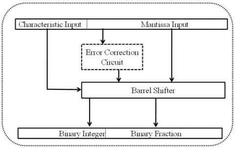
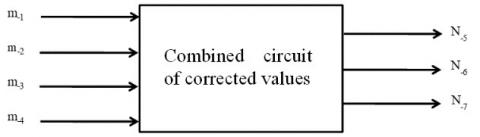
From 1962, researchers were trying continuously to propose error-free and hardware efficient approaches to get efficient and accurate antilogarithm [5, 10, 27, 29-35]. The entire antilogarithm converter process was adopted broadly in three categories of methods. The first is called the polynomial approximation-based method, second is called Read Only Memory (ROM) based method and the third is called shift-and-add based method. The general architecture of the antilogarithm converter with a correction circuit is shown in Figure 2. Mitchell’s proposed logarithmic and antilogarithmic converters based on a one-region linear approximation scheme in 1962 [10]. In 1970, Hall et al. proposed a 2-region and 4-region antilogarithmic converter by using piecewise-linear approximation schemes. Here, better accuracy achieved by the penalty of hardware [5]. SanGregory was proposing a correcting algorithm in 1999 by using mantissa’s four most significant bits for correction which makes this algorithm simple and fast [26]. Abed et al. were proposing a multi-region correction antilogarithmic converter in 2003. It found low errors but suffers from hardware overhead [27].
Figure 2. The general architecture of the antilogarithm converter with error correction circuit
In 2006, Kim et al. have proposed the 8-region piecewise linear approximation. It can reduce the approximation errors, but suffers from hardware overhead due to many regions of approximation [28]. A similar approach of 2-region bit-level manipulation has been used to achieve accuracy for an antilogarithmic converter [21, 22]. Kuo et al. have proposed 4-region shift-and-add approximations based antilogarithmic converter in 2012. It has near to 0.56 % error with tolerable area overhead [30]. In 2016, Juang et al. have given two-region antilogarithm approximation ranges -0.60 to 1.72 and ranges over 2.3232 for antilogarithm converter [31]. Durgesh Nandan et al. have suggested efficient hardware at the same error cost in comparison of reported design in 2016 and 2017, [8, 32]. Kuo et al. have again suggested error minimization for multi regions correction based on 11, 14 and 28-regions in 2016 with efficient hardware architectures. It reduces error which results from 1.8319%, 1.3436% and 0.6% [33]. Durgesh Nandan et al. have suggested efficient hardware at the same error cost in comparison to a reported design by Kuo et al. in 2017 for 11-region [34]. Again in 2019, Durgesh et al. [35] have proposed the compact and errorless 16-region error correction scheme for antilogarithm converter which gives better results in terms of hardware overhead as well as accuracy as compared to the reported literature [30-34]. By using ROM, a fast and more accurate conversion is possible. But, the hardware overhead may tremendously higher while the bit width of inputs increases [26, 31, 33]. On the other hand, the use of polynomial approximations can reduce hardware, at the cost of accuracy and speed. Many authors have reported an improvement in accuracy with a trade-off among area, speed, and power [26, 27, 30, 31, 33]. But the problem is that some of them targeting the only accuracy while some others have imposed large areas and long computation time. In other words, they fail to establish design trade-off means error minimization with an efficient architecture. Therefore, suggesting 11-region and 17-region antilogarithm converter design. It is efficient in terms of error and hardware complexity.
On behalf of reported design, it was found that error is not uniform in some conditions. For error improving in any straight line, there is a simple approach that can add the difference of approximated value minus actual value. But in many cases, the error varies in a different segment in different percentage [30]. It can’t give a significant result. For the best result, it can sub-divide the entire line into sub-regions and add the mean difference of correction terms in a specified defined range. But, increasing the number of sub-sections has reverse relation with hardware. This research work focuses on error minimization as well as significant hardware gain. The proposed 11-region or 17-region has a proper selection of fractional region which decides the error in that particular region. It will offer high performance with a small approximation error, shorter delay, and smaller hardware cost compared to the methods [30-35].
It is desirable to have lower error possibility with a sum of multiple regions error correction terms in a defined range. Since we have to compare the performance of proposed methods with reported methods; therefore, we take the same design parameters. In this section, we present the proposed antilogarithmic converters for 11-region and 17-region error correction. Multi-region error correction adder and subtractor circuit can be used to achieve better design trade-off among accuracy, area consumptions and speed by using the proper selection of fractional region decides the error in that particular region. Deciding the fractional region is a key factor that generates an error multiple of power 2 or as-near-possible to that. Error decides the subtraction term. Since optimized hardware gives an extra advantage to reported methods. Therefore, we minimize hardware. We have a straight-line ax+b. The entire straight line of the error correction scheme is segmented into 11-region and 17-region. It lies between 0 and 1, and to add or subtract the corresponding error correction scheme values. Here, it is worth mentioning that a small error percentage at the first and last region was found so, there is no need to apply the error correction scheme at these first and the last region.
3.1 Proposed method
The proposed piecewise-linear approximation is given by Eq. (1) and error percent is given in Eq. (2).
\(\text{Y}={{2}^{k'}}{{2}^{m'}}\) (1)
where, k' is any integer and m' lies between zero and one.
\(\text{Percent Error (PER)}=(\frac{(1+m')-{{2}^{m'}}}{{{2}^{m'}}})\times 100,\text{ 0}\le m'<\text{1}\) (2)
Here, Percent Error (PER) is defined as the ratio of difference of percentage of approximated value and actual value and actual value. The approximation errors are obtained by Mitchell’s method for each sub-region [10]. The input format of ‘x’ for antilogarithmic conversion supposed to be x=0.m-1 m2 m-3m-4 up to x-26. Here, we use only mantissa's four most significant bits (MSB) for adjustment of the concatenated result. Four bits of MSB can provide both accuracy and hardware complexity but three or five bits of MSB fail to provide an acceptable design trade-off. The mathematical formulation of proposed antilogarithmic conversion and error correction value is shown in Eqns. (3) and (4).
\(\begin{align} & \text{Antilog(A)=}{{\text{2}}^{\text{A}}}\text{=}{{\text{2}}^{\text{p }\!\!'\!\!\text{ }}}\times {{2}^{x'}} \\ & ={{2}^{\text{p }\!\!'\!\!\text{ }}}(1+x'+\text{error correction value) } \\ & \text{Where 0}\le \text{x }\!\!'\!\!\text{ 1} \\\end{align}\) (3)
\(\text{Error correction value = c = }\pm \sum\limits_{i}{{{2}^{-i}}}\) (4)
where, ‘i’ is a positive integer value.
The proposed 11 or 17 regions have the proper selection of fractional region decides the error in that particular region. Here key factor is that deciding the fractional region in that way which generates an error which is multiple of power 2 or as near possible to that. Error decides the subtraction term. For hardware minimization, it gives an extra advantage to reported methods. We suggest best-optimized hardware as with less error. If we have selected other reasons then these may not be able to full-fill the design trade-off. For example, if N = 17, the ‘k’ can be partitioned into [0, 0.03), [0.03, 0.06), [0.06, 0.09), [0.09, 0.12), [0.12, 0.15), [0.15, 0.1875), [0.1875, 0.21875), [0.21875,0.25), [0.25, 0.3125), [0.3125, 0.375), [0.375,0.6875), [0.6875,0.75), [0.75,0.8125), [0.8125,0.860), [0.860,0.905), [0.905,0.955) and [0.955,1.00), respectively. Here, we partitioned 'k' in a manner that creates the minimum error. The fine-tuning process will be manually adjusted to get the minimum total percent errors after obtaining the optimal values of the error correction coefficient. We can also obtain antilogarithmic conversions for 11-region and 17-region. Antilogarithmic conversion is expressed in Eq. (5), with the compensating values by using some algorithm as given in Table 1 and Table 2.
\({{\text{A}}_{\text{proposed}}}\text{=}{{\text{2}}^{\text{p }\!\!'\!\!\text{ }}}\times {{2}^{x'}}\approx {{2}^{\text{p }\!\!'\!\!\text{ }}}(1+x'+\text{c), 0}\le \text{x }\!\!'\!\!<\text{ 1}\) (5)
The values of ‘X’ are set to ‘0’ and the values of ‘c’ for each sub-region are given in Table 1 and Table 2.
Table 1. Parameters of the proposed converter using 11 region error correction schemes
|
Items |
Fractional region |
Error |
Subtraction terms |
|
1 |
[0, 0.055) |
0.0161 |
0 |
|
2 |
[0.055, 0.115) |
0.0320 |
-(1/64) |
|
3 |
[0.115, 0.186) |
0.0483 |
-(1/32) |
|
4 |
[0.186, 0.250) |
0.0607 |
-(1/32+1/64) |
|
5 |
[0.250, 0.360) |
0.0765 |
-(1/16) |
|
6 |
[0.360, 0.686) |
0.771 |
-(1/16+1/64) |
|
7 |
[0.686, 0.75) |
0.0682 |
-(1/16) |
|
8 |
[0.75,0.810) |
0.0567 |
(1/32+1/64) |
|
9 |
[0.810, 0.875) |
0.0409 |
-(1/32) |
|
10 |
[0.875, 0.955) |
0.0164 |
-(1/64) |
|
11 |
[0.955, 1) |
0 |
0 |
According to Eq. (5), all the operations for compensation are based on additions or subtractions, achieving simple and feasible circuit implementations. It is noted in Eq. (3) that the term (1 + X’ + error correction value) multiplied by ‘2p’’can be implemented with hard-wired connections of the corresponding bits of the values (1 + X’+ error correction value). Thus, multiplication and shift operations may be avoided. Since our algorithm produces the error correction values to consider lower percent errors.
Table 2. Parameters of the proposed converter using 17 region error correction schemes
|
Items |
Fractional Region |
Error |
Subtraction terms |
|
1 |
[0, 0.03) |
0.0089 |
0 |
|
2 |
[0.03, 0.06) |
0.0175 |
-(1/128) |
|
3 |
[0.06, 0.09) |
0.0256 |
-(1/64) |
|
4 |
[0.09,0.12) |
0.0332 |
-(1/64+1/128) |
|
5 |
[0.12, 0.15) |
0.0404 |
-(1/32) |
|
6 |
[0.15, 0.1875) |
0.0471 |
-(1/32+1/128) |
|
7 |
[0.1875,0.21875) |
0.0550 |
-(1/32+1/64) |
|
8 |
[0.21875,0.25) |
0.0607 |
-(1/32+1/64+1/128) |
|
9 |
[0.25, 0.3125) |
0.0706 |
-(1/16) |
|
10 |
[0.3125, 0.375) |
0.0781 |
-(1/16+1/128) |
|
11 |
[0.375, 0.6875) |
0.0770 |
-(1/16+1/64) |
|
12 |
[0.6875, 0.75) |
0.0682 |
-(1/16) |
|
13 |
[0.75, 0.8125) |
0.0562 |
-(1/32+1/64+1/128) |
|
14 |
[0.8125,0.860) |
0.0449 |
-(1/32+1/64) |
|
15 |
[0.860,0.905) |
0.0324 |
-(1/32) |
|
16 |
[0.905,0.955) |
0.0164 |
-(1/64) |
|
17 |
[0.955,1) |
0 |
0 |
Table 3. Conditions to add the 11-region corrected values
|
m-1m-2 m-3m-4 |
Corrected value for antilogarithm |
m-1m-2 m-3m-4 |
Corrected value for antilogarithm |
||||
|
2-4 |
2-5 |
2-6 |
2-4 |
2-5 |
2-6 |
||
|
0000 |
0 |
0 |
0 |
1000 |
1 |
0 |
1 |
|
0001 |
0 |
0 |
1 |
1001 |
1 |
0 |
1 |
|
0010 |
0 |
1 |
0 |
1010 |
1 |
0 |
1 |
|
0011 |
0 |
1 |
1 |
1011 |
1 |
0 |
0 |
|
0100 |
1 |
0 |
0 |
1100 |
0 |
1 |
1 |
|
0101 |
1 |
0 |
0 |
1101 |
0 |
1 |
0 |
|
0110 |
1 |
0 |
1 |
1110 |
0 |
0 |
1 |
|
0111 |
1 |
0 |
1 |
1111 |
0 |
0 |
1 |
Table 4. Conditions to add the 17-region corrected values
|
m-1m-2 m-3m-4 |
Corrected value for antilogarithm |
m-1m-2 m-3m-4 |
Corrected value for antilogarithm |
||||||
|
2-4 |
2-5 |
2-6 |
2-7 |
|
2-4 |
2-5 |
2-6 |
2-7 |
|
|
0000 |
0 |
0 |
0 |
0 |
1000 |
1 |
0 |
1 |
0 |
|
0001 |
0 |
0 |
1 |
0 |
1001 |
1 |
0 |
1 |
0 |
|
0010 |
0 |
1 |
0 |
0 |
1010 |
1 |
0 |
1 |
0 |
|
0011 |
0 |
1 |
1 |
0 |
1011 |
1 |
0 |
0 |
0 |
|
0100 |
1 |
0 |
0 |
0 |
1100 |
0 |
1 |
1 |
1 |
|
0101 |
1 |
0 |
0 |
1 |
1101 |
0 |
1 |
1 |
0 |
|
0110 |
1 |
0 |
1 |
0 |
1110 |
0 |
1 |
0 |
0 |
|
0111 |
1 |
0 |
1 |
0 |
1111 |
0 |
0 |
1 |
0 |
Therefore, antilogarithmic converters can achieve high accuracy as compared to the reported methods [27, 31, 33]. The conditions are taken out as per the equation (5) to add the corrected values. These conditions are based on the values of ‘c’ for each sub-region is given in Table 1 and Table 2. With the help of Table 1 and Table 2, we draw the corrected values of 2-4, 2-5, 2-6, and 2-7 for 11-region and 17-region, which are shown in Table 3 and Table 4.
3.2 Hardware implementation
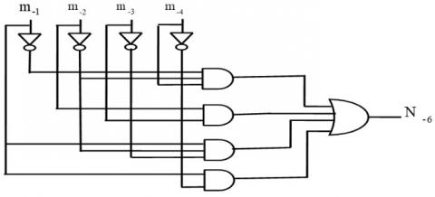
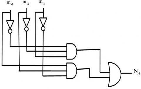
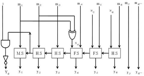
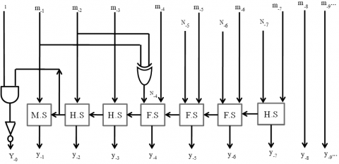
The proposed antilogarithm converter architectures for 11-region and 17-region with error correction schemes are shown in Figure 3(a), (b) and 4 (a) show the architecture of sub-component. Figure 3 (c) and 4 (b) show the main architecture of the 11-region and 17-region with an error correction scheme.
(a)
(b)
(c)
Figure 3. (a), (b) are sub-components and (c) the proposed architecture of the 11-region error correction scheme
(a)
(b)
Figure 4. (a) sub-components and (b) the proposed architecture of the 17-region error correction scheme
Here, the main challenge is to reduce the error percentage without the hardware penalty. It is well-known that on increasing the number of partitions of antilogarithm converter the error percentage is decreased at the cost of the hardware penalty. In this section, we analyze the error, synthesis results, and comparisons to present the proposed design as an error and hardware efficient.
4.1 Error analysis
Error analysis can be evaluated by using three parameters, the Maximum Positive Percent Error (MPPE), Maximum Negative Percent Error (MPPE) and the Percentage Error Range (PER). The results are shown in Table 5. The Table 5 shows that our proposed method for 11-region with error correction scheme gives 1.441% in comparisons of Mitchell’s 6.1476%, Hall’s 2- regions 1.5042%, Abed & Siferd’s 2-region 1.331%, Juang et al. 2-region 1.72% and Kuo et al. 11-region 1.7327% MPPE. MNPE of -0.1436% in comparisons of Mitchell’s 0%, Hall’s 2- region -1.1155%, Abed & Siferd 2-region -0.5631%, Juang et al. 2-region -0.6% and Kuo et al. 11-region -0.0992%.
Table 5. Comparison table of percent error for the proposed antilogarithm converters for 11-region and 17-region with error correction schemes
|
|
Region |
MPPE |
MNPE |
PER |
|
Mitchell 10 |
1 |
6.1476 |
0 |
6.1476 |
|
Hall 5 |
2 |
1.5042 |
-1.1155 |
2.6197 |
|
Abed & Siferd 27 |
2 |
1.331 |
-0.5631 |
1.8941 |
|
6 |
0.9572 |
-0.5786 |
1.5358 |
|
|
Juang 31 |
2 |
1.72 |
-0.6 |
2.3232 |
|
Kuo 33 |
11 |
1.7327 |
-0.0992 |
1.8319 |
|
14 |
1.2 |
-0.1436 |
1.3436 |
|
|
Proposed (11-Region) |
11 |
1.554 |
-0.1436 |
1.697 |
|
Proposed (17-Region) |
17 |
0.94 |
-0.1436 |
1.084 |
In terms of PER, we found that our proposed method for 11-region with error correction scheme gives only 1.697% in comparisons of Mitchell’s 6.1476%, Hall’s 2-regions 2.6197%, Abed & Siferd’s 2-region 1.8941%, Juang et al. 2-region 2.3232% and Kuo et al. 11-region 1.8319%. Table 5 shows that our proposed method for 17-region with error correction scheme gives 0.94% MPPE in comparisons of Abed & Siferd’s 6 -region 0.9572%, and Kuo et al. 14-region 1.2%. MNPE of -0.1436% in comparisons of Abed & Siferd’s 6-region -0.5786% and Kuo et al. 14-region -0.1436%. In terms of PER, we found that our proposed method for 17-region with error correction scheme gives only 1.084% in comparisons of Abed & Siferd’s 6-region 1.5358% and Kuo et al. 14-region 1.3436%. From Table 5 it is observed that the proposed method has given less percentage error range in comparisons of the reported designs. The proposed method for 11-region with error correction scheme gives a 7.36% less percentage error range in comparison to the latest design given by Kuo et al. for 11-region with constant compensation scheme. The proposed method for the 17-region error correction scheme has a 19.32% less percentage error range in comparison to the most recent design as proposed by Kuo et al. for 14-region with constant compensation scheme.
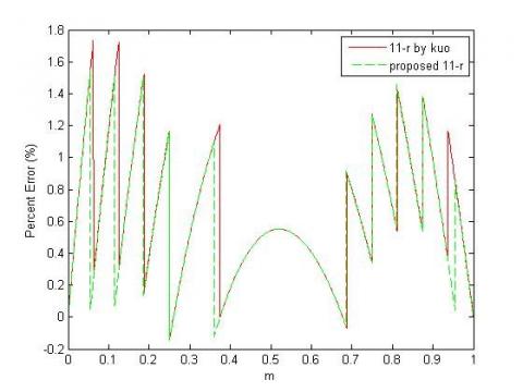
Figure 5. Analysis of percent errors for proposed antilogarithm converters for the 11-region error correction scheme and the reported converter using the 11-region constant compensation scheme
Figure 6. Analysis of percent errors for proposed antilogarithm converters for 17-region error correction schemes with reported converter using a 14-region constant compensation scheme
Analysis of errors for the proposed antilogarithm converters for 11-region and 17-region with error correction schemes and the converter for 11-region and 14-region with constant compensation schemes as proposed by Kuo is shown in Figure 5 and Figure 6.
All are MATLAB 12.1 version based simulation results and with the help of the generated graph, we easily observed that for every sub-region our proposed method has given less error percentage than of the reported methods.
4.2 Hardware complexity
The theoretical analysis for hardware complexity is done as a count of gates. The gate count for the proposed 11-region and 17-region with error correction scheme and reported structures are listed in Table 6. Based on theoretical hardware complexities analysis, we can say that the proposed antilogarithm converter for 11-region and 17-region with an error correction scheme is much hardware efficient in comparison to reported antilogarithm converter for 11-region and 14-region with constant compensation scheme.
Table 6. General comparison of hardware complexities of reported and proposed 11 and 17-region error correction schemes for antilogarithm converter
|
Structure |
Antilogarithm Existing33 |
Antilogarithm Proposed |
||
|
11-region |
14-region |
11-region |
17-region |
|
|
AND |
34 |
39 |
20 |
34 |
|
OR |
15 |
17 |
7 |
12 |
|
NOT |
25 |
27 |
17 |
21 |
|
XOR |
12 |
14 |
10 |
11 |
The reported antilogarithm converter for 11-region and 14-region with constant compensation scheme and proposed antilogarithm converter for 11-region and 17-region with error correction scheme at 65 nm CMOS technology node at the Synopsys Design Compiler has been designed and synthesized. Synthesis results for various parameters are compared with the reported antilogarithm converter for 11-region and 14-region with constant compensation scheme as listed in Table 7. The proposed 11-region antilogarithm converter involves 61% less ADP and 49.82% energy in comparisons of reported 11-regions antilogarithmic converter. The proposed 17-region antilogarithm converter involves 48.02% less ADP and 32.53% energy in comparisons of the reported 14-region antilogarithmic converter.
Table 7. Synopsys synthesis results for the proposed 11-region and 17-region with error correction circuits and the reported structures for the antilogarithmic converter
|
Structure |
DAT (ns) |
Area (µm2) |
Power (µW) |
ADP (µm2*ns) |
% gain in ADP |
Energy (n J) |
% gain in EPS |
|
Reported 31 (2-region) |
0.66 |
111.96 |
3.3678 |
73.8936 |
---------- |
2222.74 |
---------- |
|
Reported 33 (11-region) |
0.81 |
203.04 |
4.068 |
164.46 |
--------- |
3295.08 |
---------- |
|
Reported 35 (11-region) |
0.67 |
144.58 |
3.6171 |
96.86 |
---------- |
2423.45 |
----------- |
|
Reported 33 (14-region) |
0.83 |
223.56 |
4.6571 |
185.55 |
--------- |
3864.48 |
---------- |
|
Proposed (11-region) |
0.59 |
108.72 |
2.803 |
64.14 |
61 |
1653.77 |
49.82 |
|
Proposed (17-region) |
0.69 |
139.32 |
3.7791 |
96.13 |
48.02 |
2607.51 |
32.53 |
The proposed antilogarithmic converter for 11-region and 17-region is found a significant gain in terms of accuracy and hardware. 11-region antilogarithmic converter gives a 7.36% less percentage error range in comparison of reported design given by Kuo et al. 17-region antilogarithmic converter provides 19.32% less percentage error range in comparison of the reported design is given by Kuo et al. for the 14- region constant compensation scheme. 11-region antilogarithmic converter gives 61% less ADP and 49.82% less energy in comparisons of reported 11-regions antilogarithmic converter. 17-region antilogarithmic converter gives 48.02% less ADP and 32.53% less energy in comparisons of the reported 14-region antilogarithmic converter. The proposed converter design is useful for real-time DSP and image applications.
This work was supported by the Jaypee University of Engineering & Technology, Guna, Madhya Pradesh, India. Dr. Jitendra Kanungo and Dr. Anurag Mahajan helped to improve this article by their valuable suggestions.
[1] Sun, Y., Kim, M.S. (2011). A high-performance 8-Tap FIR filter using logarithmic number system. IEEE International Conference on Communications (ICC), pp. 1-5. https://doi.org/10.1109/icc.2011.5962827
[2] Nam, B.G., Kim, H.J., Yoo, H.J. (2008). Power and area-efficient unified computation of vector and elementary functions for handheld 3D graphics systems. IEEE Transactions on Computers, 57(4): 490-504. https://doi.org/10.1109/TC.2008.12
[3] Basetas, C., Kouretas, I., Paliouras, V. (2007). Low-power digital filtering based on the logarithmic number system. Proc.17th Workshop Power and Timing Modeling, Optimization and Simulation, pp. 546-555. https://doi.org/10.1007/978-3-540-74442-9_53
[4] Kouretas, I., Basetas, C., Paliouras, V. (2013). Low-power logarithmic number system addition/subtraction and their impact on digital filters. IEEE Transactions on Computers, 62(11): 2196-2209. https://doi.org/10.1109/TC.2012.111
[5] Hall, E.L., Lynch, D.D., Dwyer III, S.J. (1970). Generation of products and quotients using approximate binary logarithms for digital filtering applications. IEEE Trans. Computers, 55(2): 97-105. https://doi.org/10.1109/T-C.1970.222874
[6] Mahalingam, V., Rangantathan, N. (2006). Improving accuracy in Mitchell's logarithmic multiplication using operand decomposition. IEEE Transactions on Computers, 55(2): 1523-1535. https://doi.org/10.1109/TC.2006.198
[7] Abid, Z., Dalia, A. El-Dib, Mudassir, R. (2016). Modified operand decomposition multiplication for high performance parallel multipliers. Journal of Circuits, Systems, and Computers, 25(12). https://doi.org/10.1142/S0218126616501498
[8] Nandan, D., Kanungo, J., Mahajan, A. (2017). An efficient VLSI architecture design for logarithmic multiplication by using the improved operand decomposition. Integration, the VLSI Journal, 58: 134-141. https://doi.org/10.1016/j.vlsi.2017.02.003
[9] Nandan, D., Kanungo, J., Mahajan, A. (2018). An error-efficient gaussian filter for image processing by using the expanded operand decomposition by using multiplication. Journal of Ambient Intelligence and Humanized Computing. https://doi.org/10.1007/s12652-018-0933-x
[10] Mitchell, J.N. (1962). Computer multiplication and division using binary logarithms. IRE Transactions on Electronic Computers, 11(6): 512-517. https://doi.org/10.1109/TEC.1962.5219391
[11] Brubaker, T.A., Becker, J.C. (1975). Multiplication using logarithms implemented with read-only-memory. IEEE Trans. Computers, 24(8): 761-766. https://doi.org/10.1109/T-C.1975.224307
[12] Nandan, D., Kanungo, J., Mahajan, A. (2017). An efficient VLSI architecture for iterative logarithmic multiplier. IEEE 4th International Conference on Signal Processing and Integrated Networks, pp. 419-423. https://doi.org/10.1109/SPIN.2017.8049986
[13] Nandan, D., Mahajan, A., Kanungo, J., (2018). An efficient architecture of iterative logarithmic multiplier. International Journal of Engineering & Technology (UAE), 7(2.16): 24-28. https://doi.org/10.14419/ijet.v7i2.16.11410
[14] Naziri, S.Z.M., Ismail, R.C., Shakaff, A.Y.M. (2014). The design revolution of logarithmic number system architecture. IEEE International conference on Electrical, Electronics and System Engineering, pp. 5-10. https://doi.org/10.1109/ICEESE.2014.7154603
[15] Muscedere, R., Dimitrov, V., Jullien, G.A., Miller, C.W. (2005). Efficient techniques for binary-to-multi digit multi-dimensional logarithmic number system conversion using range-addressable look-up tables. IEEE Trans. Computers, 54(3): 257-272. https://doi.org/10.1109/ASAP.2002.1030711
[16] Arnold, M.G., Collange, S. (2011). A real/complex logarithmic number system ALU. IEEE Transactions on Computers, 60(2): 202-213. https://doi.org/10.1109/TC.2010.154
[17] Paliouras, V., Stouraitis, T. (2000). Logarithmic number system for low-power arithmetic. Proc. Int’l Workshop - Power and Timing Modeling, Optimization and Simulation, pp. 285-294. https://doi.org/10.1007/3-540-45373-3_30
[18] Johansson, K., Gustafsson, O., Wanhammar, L. (2008). Implementation of elementary functions for logarithmic number systems. IET Computer & Digital Techniques, 4: 295-230. https://doi.org/10.1049/iet-cdt:20070080
[19] Das, D., Mukhopadhyaya, K., Sinha, B.P. (1995). Implementation of four common functions on an LNS co-processor. IEEE Transactions on Computers, 44(1): 155-161. https://doi.org/10.1109/12.367997
[20] Abed, K.H., Sifred, R.E. (2003). CMOS VLSI implementation of a low- power logarithmic converter. IEEE Transactions on Computers, 52(11): 1421-1433. https://doi.org/10.1109/TC.2003.1244940
[21] Low, J.Y.L., Jong, C.C. (2005). Unified Mitchell-based approximation for efficient logarithmic conversion circuit. IEEE Trans. Computers, 64: 1783-1797. https://doi.org/10.1109/TC.2014.2329683
[22] Juang, T.B., Chen, S.H., Cheng, H.J. (2009). A lower error and ROM-free logarithmic converter for digital signal processing applications. IEEE Transactions on Circuits and Systems II, 56(12): 931-935. https://doi.org/10.1109/TCSII.2009.2035270
[23] Juang, T.B., Meher, P.K., Jan, K.S. (2011). High performance logarithmic converters using novel two-region bit-level manipulation schemes. IEEE International Symposium on VLSI Design, Automation and Test, pp. 1-4. https://doi.org/10.1109/VDAT.2011.5783555
[24] Chaudhary, M., Lee, P. (2014). Two-stage logarithmic converter with reduced memory requirements. IET Comput Digit Tech, 8(1): 23-29. https://doi.org/10.1049/iet-cdt.2012.0134
[25] Liu, C.W., Ou, S.H., Chang, K.C., Lin, T.C., Chen, S.K. (2016). A low-error, cost-efficient design procedure for evaluating logarithms to be used in a logarithmic arithmetic processor. IEEE Trans Computer, 65(4): 1158-1164. https://doi.org/10.1109/TC.2015.2441696
[26] SanGregory, S.L., Siferd, R.E., Brother, C, Gallagher, D. (1999). Low-power logarithm approximation with CMOS VLSI implementation. IEEE Midwest Symp. Circuits and Systems, pp. 388-391. https://doi.org/10.1109/MWSCAS.1999.867287
[27] Abed, K.H., Sifred, R.E. (2003). CMOS VLSI implementation of a low-power antilogarithmic converter. IEEE Trans. Computers, 52: 1221-1228. https://doi.org/10.1109/TC.2003.1228517
[28] Kim, H., Nam, B.G., Sohn, J.H., Woo, J.H., Yoo, H.J. (2006). A 231-MHz, 2.18-mW 32-bit logarithmic arithmetic unit for fixed-point 3-D graphics system. IEEE Journal of Solid-State Circuits, 41(11): 2373-2381. https://doi.org/10.1109/JSSC.2006.882887
[29] Paul, S., Jayakumar, N., Khatri, S.P. (2009). A fast hardware approach for approximate, efficient logarithm and antilogarithm computations. IEEE Transactions on Very Large-Scale Integration Systems, 17(2): 269-277. https://doi.org/10.1109/TVLSI.2008.2003481
[30] Kuo, C.T., Juang, T.B. (2012). A lower error antilogarithmic converter using novel four-region piecewise-linear approximation. IEEE Asia Pacific Conference on Circuits and Systems, pp. 507-510. https://doi.org/10.1109/APCCAS.2012.6419083
[31] Juang, T.B., Kuo, H.L., Jan, K.S. (2016). Lower-error and area-efficient antilogarithmic converters with bit-correction schemes. Journal of the Chinese Institute of Engineers, 39(1): 57-63. https://doi.org/10.1080/02533839.2015.1070692
[32] Nandan, D., Kanungo, J., Mahajan, A. (2016). An efficient VLSI architecture design for antilogarithmic converter by using the error correction scheme. International Conference on Signal Processing (ICSP 2016), pp. 1-5. https://doi.org/10.1049/cp.2016.1445
[33] Kuo, C.T., Juang, T.B. (2016). Area-efficient and highly accurate antilogarithmic converters with multiple regions of constant compensation schemes. Microsystem Technology, 22(1): 219-225. https://doi.org/10.1007/s00542-016-3238-z
[34] Nandan, D., Mahajan, A., Kanungo, J. (2017). An efficient antilogarithmic converter by using 11-regions error correction scheme. IEEE 4th International Conference on Signal Processing, Computing and Control (ISPCC), pp. 118-121. https://doi.org/10.1109/ISPCC.2017.8269661
[35] Nandan, D., Kumar, K., Kanungo, J., Mishra, R.K. (2019). Compact and errorless 16-Region error correction scheme for antilogarithm converter. IEEE International Conference on Electrical, Electronics and Computer Engineering (UPCON), pp. 1-5. https://doi.org/10.1109/UPCON47278.2019.8980240