Qiang Liu | Xin He | Fengwei Guan | Yuchen Zhao | Fan Jiang | Fuxiang Tian | Shuxin Wang*
© 2019 IIETA. This article is published by IIETA and is licensed under the CC BY 4.0 license (http://creativecommons.org/licenses/by/4.0/).
OPEN ACCESS
Based on the analysis of the pointing accuracy of the optical sensor in a star sensor, this paper introduces the geometric accuracy of the star sensor as an external orientation element that affects the optical remote sensing image and analyzes the characteristics of the installation method of the star sensor in different optical remote sensors. The key factors affecting the pointing accuracy of the star sensor are considered, and the geometrical accuracy of the image is improved by analyzing the installation method of the star sensor, the star sensor bracket design, and the star sensor thermal control component. Achievable measures are made, and the pointing stability of the star sensor is verified through a ground test and by measuring the temperature fluctuations of the orbiting sensor. Through ground testing and on-orbit testing, the star sensor bracket has a temperature fluctuation of <±1 ℃ in one photography cycle, and the star sensor's attitude error around the axis is less than 5", so the uncontrolled geometric positioning accuracy of the image product can be obtained as 11.4 m (rms).
star sensor, spatial optical remote sensor, external orientation element, pointing accuracy
The geometric accuracy of remote sensing images is a major aspect of comprehensively measuring satellite and camera capabilities. Foreign optical commercial satellites, such as the US GeoEye2, GeoEye3 and WorldView-3/WorldView-4, use a traditional long focal length and large total reflection aperture. A reconnaissance camera, with its advanced satellite-integrated imaging link design, simulation verification and on-track calibration technology, has a geometric positioning accuracy for high-resolution images that reaches several meters. The WorldView-2 satellite image positioning accuracy with no ground control is 4.6 m~10.7 m. The image positioning accuracy of the Pleiades satellite with ground control reaches 1m, and the positioning accuracy without ground control reaches 10 m [1]. The star sensor on the satellite plays an important role for such high positioning accuracy. Currently, the optical precisions of the optical remote sensing satellites in China are relatively low, and the positioning accuracies of the geometric ground-free control points are approximately 50 m~100 m; thus, there are still large gaps between domestic and foreign high-resolution remote sensing satellites and between three-dimensional surveying and mapping satellites. To achieve high geometric accuracy of the remote sensing images, it is necessary to increase the focus on the star sensor. According to the calculations, when the angle between the optical axis of the satellite remote sensor and the star sensor randomly changes by an angle of several tens of angular seconds, the resulting positioning error is approximately a hundred meters [2-4]. Many researchers in China have analyzed the geometric accuracy of satellite images. For example, Jin et al. [2] conducted an overall design analysis to improve the geometric accuracy of remote sensing satellite images. The various factors affecting the geometric accuracy of images in the overall design of satellites and related measures were also comprehensively analyzed and proposed [5, 6]. Tian [7] analyzed the influence of a star sensor on the satellite attitude calculation accuracy from the perspective of star sensor imaging. Yu et al. [8] made a preliminary analysis of the orientation accuracy of the GeoEye-1 satellite’s imagery. Jiang et al. [9] analyzed the design of the star sensor bracket of the mapping camera from the thermal side of the star sensor. Gao et al. [10] determined that the image positioning accuracy of the resource ZY-3 mapping satellite is guaranteed from the key structure of the star sensor bracket and camera bracket in a high-stability design. The ZY-3 surveying and mapping satellite has a plane accuracy of 11.7m under uncontrolled conditions. Because of its extremely high pointing requirements, the star sensor is placed at the base of the surveying camera. In addition to the surveying and mapping camera, the geometric imaging quality requirements of the medium and high resolution optical imaging camera are increasing. To improve the geometric quality of the image, it is also necessary to consider the installation method of the star sensor. Star sensor mounting bracket on ALMA array telescope uses Invar alloy to reduce thermal deformation [11, 12]. SOFIAoptical telescope uses FPI, FFI and WFI star sensors. In order to improve pointing stability, WFI and FFI are mounted on the main mirror frame; ESA's Sentinel-2 satellite push-broom multi-spectral camera, in order to achieve the geometric positioning requirements of 20 m without ground control points, a star tracker is installed directly on the main bearing structure of the camera to ensure the best pointing performance of the telescope [13, 14]. However, there is no publicly available literature on how to improve the pointing accuracy of high-resolution optical remote sensors for large imaging field-of-view Three-Mirror Anastigmatic (TMA) optical systems. Based on the analysis of the pointing accuracy of optical sensors in star sensors, the influence of star sensors on the geometric accuracy of optical remote sensing images is analyzed. The key factors affecting the pointing accuracy of star sensors are considered item by item, and the stars are improved for these factors. The sensor points towardsstability to improve the geometrical accuracy of the image. Finally, the design scheme and achievable measures are given, and the pointing stability of the star sensor is verified by an analytical calculation and a ground test [15].
The geometric accuracy indicators of optical remote sensing satellite imaging mainly include absolute positioning accuracy and relative positioning accuracy. The absolute positioning accuracy refers to the error between the geographical coordinates of the points on the high-resolution remote sensing image and the actual geographical coordinates. The relative positioning accuracy refers to the measurements on the image. The obtained relative position and the error of the true relative position reflect the random error of different positions in the image. Errors that affects the geometric quality of CCD imaging, i.e., the relative positioning error, are classified as internal errors. Errors that do not affect the geometric quality of CCD imaging but affect the absolute positioning accuracy are called external errors [1]. Among them, the attitude error of the star sensor is an external error. The star sensor gives the satellite’s three-axis attitude and guide the satellite when adjusting the attitude; therefore, the star sensor points towards high-resolution optical remote sensing. The image geometric positioning accuracy of the device plays a crucial role [16, 17].
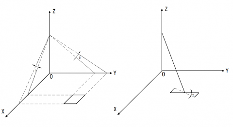
The influence of the attitude observation error of the star sensor on the positioning accuracy includes the measurement error of the pitch, roll, and yaw angles. The influence of the plane positioning accuracy is then analyzed. The roll angle α and the pitch angle β are analyzed. The influence of the error is the most obvious, and the influence of the yaw angle γ error is relatively small (which will cause a rotation effect of the error distribution). From the simple geometric relationship, at an orbital height of 650 km, the attitude error of 1 arc/second in the satellite roll angle or yaw angle observation will cause a positioning error of 3.15m; therefore, to achieve a pointing accuracy of 15m, the pointing accuracy must be increased to within 5" [18, 19].
Figure 1. Schematic diagram of the influence of attitude error on the geometric positioning accuracy
Figure 2. Star sensor working path diagram
It can be seen from the star sensor working path diagram that the ground phase star sensor and optical remote sensor need to be calibrated, as do the star sensor and satellite platform. In the past, the star sensor was usually placed on the satellite platform and gave the star sensitive data. The satellite is guided to adjust the attitude; however, from the imaging point of view there is a link error between the satellite sensor and the remote sensor, which will result in a pointing error of the remote sensor, thus affecting the absolute positioning accuracy of the image [20].
The thermal stability of the star sensor bracket determines the positioning accuracy and repeat positioning accuracy of the star sensor in orbit. When the camera is in orbit, the thermal environment alternates between the shadow area and the sun area. When the external temperature changes, the star sensor bracket is thermally deformed, causing the star sensor mounted on it to change, and the amount of change can be analyzed by the transfer matrix.
The nominal position of the star sensor installation is equivalent to the transformation matrix CSB of the satellite body’s coordinate system. When the installation deviation angle or deformation angle △S appears in a certain direction of the satellite platform, the coordinate transformation matrix from the deviation state to the nominal state is:
$C_{s \Delta}=\left[\begin{array}{ccc}{\cos (\Delta s)} & {\sin (\Delta s)} & {0} \\ {-\sin (\Delta s)} & {\cos (\Delta s)} & {0} \\ {0} & {0} & {1}\end{array}\right]$ (1)
The corresponding installation matrix with errors is CSB=CT SBCSD. To eliminate this error, the star sensor can be installed on the camera body. Thus, it is necessary to consider the influence of the star sensor component on the camera body image.
The following is an analysis of the path error from the star sensor (assuming that the three star sensors are mounted integrally on the camera body), with the optical remote sensor coordinate system {A} as the reference coordinate system, and the star sensor bracket coordinate system {B}. The star sensor's own coordinate system is {C1}, {C2}, {C3}. The vectors of each star sensor's optical axis in its own coordinate system are $^{C 1} p_{a 1},^{C 2} p_{a 2}$ and $^{C 3} p_{a 3}$. The coordinate system conversion matrix has $_{B}^{A} T,_{C 1}^{B} T,_{C 2}^{B} T$ and $_{C_{3}}^{B} T$. The vector of the optical axis of each star sensor in the reference coordinate system is determined using the following formula:
$\left\{\begin{array}{l}{^{A} P_{a 1}=_{B}^{A} T_{C l}^{B} T^{C l} P_{a 1}} \\ {^{A} P_{a 2}=_{B}^{A} T_{C 2}^{B} T^{C 2} P_{a 2}} \\ {^{A} P_{a 3}=_{B}^{A} T_{C 3}^{B} T^{C 3} P_{a 3}}\end{array}\right.$ (2)
Since the error of the star sensor $R_{x, y, z}^{a n}$ will cause a change in the transformation matrix $_{C_{n}}^{B} T$, the error of the star sensor bracket $R_{x, y, z}^{b}$ will lead to a change in the transformation matrix $_{B}^{A} T$. After introducing these two types of errors, the optical axis of each star sensor in the reference coordinate system is given in the following formula [2]:
$\left\{\begin{array}{l}{^{A} P_{a 1}^{\prime}=\left(R_{x, y, z B}^{b} T\right)\left(R_{x, y, z}^{a 1} T\right)^{C 1} P_{a 1}} \\ {^{A} P_{a 2}^{\prime}=\left(R_{x, y, z}^{b} A\right)\left(R_{x, y, z}^{a 2} B_{T}^{B} T\right)^{c 2} P_{a 2}} \\ {P_{a 3}^{\prime}=\left(R_{x, y, z}^{b} A\right)\left(R_{x, y, z}^{a 3} B_{T}^{B} T^{c^{3}} P_{a 3}\right.}\end{array}\right.$ (3)
Considering that the APS star sensor has a high stability accuracy, the attitude accuracy of a single star sensor is less than 3″ (pitch and yaw, 1σ) and its own error $R_{x, y, z}^{a n}$ is small. Therefore, the star sensor bracket is affected by the environment (mainly mechanical environment and thermal environment). The resulting error $R_{x, y, z}^{b}$ determines the positioning accuracy of the star sensor when working in orbit.
3.1 Integrated disign
The star sensor is a high-precision space attitude measuring device that uses a star as a reference frame and a starry sky as the working object. To improve the geometric positioning accuracy of high-resolution camera images, it is necessary to consider the installation method of the star sensor.
A TMA optical system has the following features: a large imaging field of view, a strong stray light suppression, and a single remote sensor that can achieve the advantages of a large width and high resolution. This is the mainstream optical design of a space optical remote sensor. Through analysis the integrated design of the sensor is determined to be the optimal design to ensure the pointing accuracy of the star sensor. The integrated design includes a three star sensor integrated design and an integrated design of a star sensor and an optical remote sensor.
Unlike the surveying camera, the stereo mapping camera (three-line camera) has a mapping base (bracket). The star sensor is placed on the mapping base/bracket such that the star sensor measurement reference is consistent with the three-line camera benchmark. The compact connection layout shortens the structural connection path between the star sensor and the three-line array camera and reduces the influence of the on-orbit space environment change on the relative geometric position of the two components.
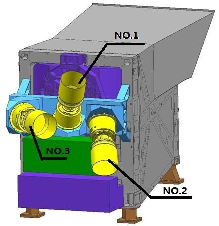
The large field of view off-axis camera is a compact optical system. There is no special base or bracket for the star sensor assembly, and it can only be placed on the camera's main bearing structure. The camera uses 3 APS star sensors. For reliability considerations, when the three star sensors are in orbit, star sensor 1 and star sensor 2 are used in combination and star sensor 3 is used as a backup. According to the user requirements, the relative angular stability of the three star sensors is required to reach 5, where "The stability of the star sensor bracket assembly is very high”. The change in the direction caused by the thermal load of the three star sensors can be maintained by relatively stable pointing via mounting the three star sensors on the same mounting surface.
Therefore, considering the relative positional relationship between the satellite platform, the star sensor, the optical remote sensor, the space requirements and the heat transfer path, the three star sensors are mounted on a star-sensitive bracket and the star-sensitive bracket is mounted on the optical remote sensor. The integrated installation of the star-sensing remote sensor and the optical remote sensor is then achieved. This design is beneficial for achieving the maximum alignment of the star-sensitive pointing with the optical axis of the optical remote sensor under the action of an external load, which fundamentally guarantees the geometry precision of the remote sensing image [21, 22].
3.2 Star sensor bracket microgravity design
The integrated design of the three star sensors places high demands on the design of the star sensor bracket. The star sensor bracket needs to be guaranteed in two aspects, namely the pointing and dynamic characteristics of the star sensor. All that needs to be considered is the stiffness design of the star sensor, including the static stiffness and dynamic stiffness, and the dynamic response at the resonant frequency needs to be minimized. The following design ideas need to be followed:
Figure 3. Star sensor component schematic
In terms of material selection, materials with a high specific stiffness and good thermal stability are selected; the support mode of the star-sensitive bracket is rationally designed, and the support mode is optimized through a calculation and analysis; the support structure is further optimized under the premise of ensuring rigidity, and the quality is reduced; the stress environment is introduced, and the deformation of the stent is quantitatively analyzed via simulation to ensure the good pointing stability of the star-sensitive bracket.
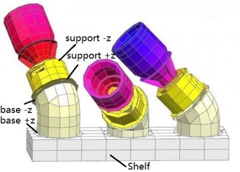
The star sensor bracket assembly mainly includes a bracket, a base and a support. The bracket is connected to the rear frame through the support structure across the main mirror back plate, and its main function is to provide a mounting foundation for the three star sensors. The bracket is made of a high-strength aluminum-based composite material, and high-precision thermal control can ensure that the bracket does not affect the accuracy of the optical system due to temperature changes. Each star sensor corresponds to a base and a stand. The base mainly serves to ensure the pointing of the star sensors. The support provides a mounting interface for the star sensor and also acts as a heat sink.
3.3 Star sensor high precision temperature control design
The star sensor is integrated with the remote sensor, as are the three star sensors. Since the star sensor is installed on the sky surface, the heat flow outside the space fluctuates greatly, which will affect the temperature level and stability of the star sensor component. This has a large impact; therefore, it requires a high-precision and a high-stability temperature control design for the star sensor components.
The high-precision temperature control design includes a heat insulation design, a heat dissipation design, a heat transfer enhancement, and an active thermal control and isothermal design. The thermal insulation design of the star sensor is divided into thermal insulation and radiation insulation. The purpose is to reduce the thermal disturbance caused by the temperature difference between the star sensor and the camera. The purpose of the radiant heat insulation is to reduce the heat flow outside the space and the radiant heat flow of the satellite and camera components to the star sensor. Through the high-precision thermal control design, the ideal working state of the star sensor with a large temperature level and low temperature fluctuation can be guaranteed, thus achieving the pointing precision of the star sensor component. The temperature level of the star-sensitive bracket is 1 °C, and the temperature control accuracy is 1 °C. The temperature fluctuation during the period is <±1 °C.
Figure 4. Star sensor component thermal control chart
4.1 Star sensor pointing stability analysis
When the APS star sensor is working in orbit, the installation interface temperature is controlled at -5~13 °C and the head temperature fluctuation is controlled at ±2 °C in each orbit period. To meet the stability requirements of the star sensor pointing to less than 5'', the star sensor bracket assembly needs to have good thermal stability. Through a thermal finite element analysis of the star-sensitive component, the temperature level and fluctuation of each connection interface of the star sensor bracket assembly are obtained. The low temperature in orbit and the high temperature in orbit are selected to analyze the change of the star sensor. The results of the analysis are shown in Table 1.
Figure 5. Thermal analysis model of the star sensor bracket assembly
Table 1. Star sensor pointing in the stability analysis
|
Working condition |
Low temperature in orbit |
High temperature in orbit |
|
-Z connection surface of the support |
8℃ |
12℃ |
|
+Z connection surface of the support |
9℃ |
13℃ |
|
-Z connection surface of the base |
17.5℃ |
19.5℃ |
|
+Z connection surface of the base |
18.5℃ |
19.5℃ |
|
Shelf |
19.7℃ |
20.3℃ |
Table 2. Star sensor pointing change (units ″)
|
|
Angle around the x axis |
Angle around the y axis |
Angle around the z axis |
Spatial angle change |
|
Star sensor NO.1 |
-0.3378 |
-1.4532 |
1.3144 |
1.4234 |
|
Star sensor NO.2 |
-0.0246 |
-2.0842 |
-0.6190 |
2.1708 |
|
Star sensor NO.3 |
0.0848 |
-0.2964 |
-0.1476 |
0.3302 |
Figure 6. Thermal deformation diagram of the star sensor bracket assembly
The temperature fields of each working condition in Table 1 were mapped in the finite element model of the star sensor component, and the thermal deformation was calculated by the Nastran solver. The calculation results were then obtained. The angular change of the low-temperature state of the orbit relative to the high-temperature state of the rail is shown in Table 2. The maximum value of the angle change of the three star sensors is 2.17′′, which satisfies the in-orbit working condition of the star sensor having a pointing stability better than 5".
4.2 Test verification
Test verification includes both ground test and on-orbit test.
1) Ground test verification
In the ground heat test, due to the limitation of the vacuum simulation equipment, it is impossible to use the theodolite to verify the real-time force and thermal stability of the star sensor in the vacuum state. Therefore, the method used involves pointing the star sensor before and after the mechanical and thermal tests. The test is conducted by measuring the angle between the test prism and the optical remote sensor pointing prism on the star sensor flange and using the optical remote sensor pointing prism as a reference to verify the pointing stability of the star sensor.
Ground test data analysis:
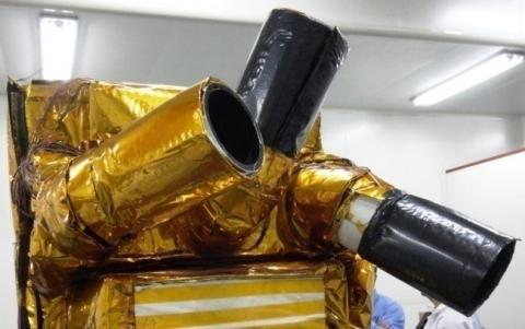
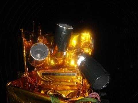
Figure 7 shows the thermal test of the star sensor assembly in a vacuum tank. The pointing accuracy of the three star sensors is retested before and after the force and heat test, and the pointing stability meets the requirements.
It can be seen from the data in the table that the maximum value of the change in the pointing angle of the three star sensors before and after the test appears in star sensor 2 with a variation of 3.6″, indicating that the pointing accuracy of the star sensor meets the requirements before and after the force heat test.
Table 3. The amount of change in the pointing angle of the star sensor before and after the test (°)
|
. |
Direction |
Before the vibrating test |
After the vibrating test |
After the heat test |
Total angle variable (″) |
|
Star sensor NO.1 |
x-axis deflection angle around the entire machine |
30.2196 |
30.2191 |
30.2198 |
1.1 |
|
y-axis deflection angle around the entire machine |
68.1930 |
68.1928 |
68.1924 |
1.9 |
|
|
z-axis deflection angle around the entire machine |
109.8525 |
109.8516 |
109.8521 |
1.2 |
|
|
Star sensor NO.2 |
x-axis deflection angle around the entire machine |
119.5163 |
119.5169 |
119.5157 |
2.2 |
|
y-axis deflection angle around the entire machine |
61.3328 |
61.3332 |
61.3333 |
2.0 |
|
|
z-axis deflection angle around the entire machine |
136.5559 |
136.5558 |
136.5569 |
3.6 |
|
|
Star sensor NO.3 |
x-axis deflection angle around the entire machine |
74.8814 |
74.8809 |
74.8811 |
0.7 |
|
y-axis deflection angle around the entire machine |
56.5791 |
56.5788 |
56.5796 |
2.2 |
|
|
z-axis deflection angle around the entire machine |
142.4525 |
142.4520 |
142.4529 |
1.4 |
Figure 7. Star sensor assembly with the entire machine thermal test
2) On-orbit test
At present, the camera is in the normal imaging mode in orbit. By examining the in-orbit temperature data of the star sensor component and verifying the correctness of the thermal stability analysis, the pointing stability of the star sensor can be obtained indirectly. The temperature of the star sensor assembly was monitored, and the temperature curve of the star sensor holder is shown in Figure 8. The flange temperature fluctuation of the star sensor is shown in Figure 9.
On-orbit test data analysis:
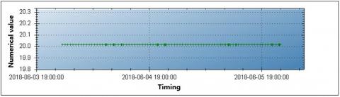
The star sensor bracket is stable at 20 °C in 45 orbital periods, and the star sensor flange temperature fluctuates between 8.6 °C and 10.3 °C (including a shaded area and positive area). The fluctuation range is less than 2 °C. The in-orbit data indicates star sensitivity. The temperature changes of the device are within the design requirements, which can ensure the pointing accuracy of the star sensor.
Figure 8. Star sensor bracket in-orbit telemetry temperature level
Figure 9. Three star sensor flange temperature levels and fluctuations
In this paper, a detailed analysis of the pointing accuracy of the star sensor is made. It is proposed that the stability of the star sensor has a great influence on the external orientation elements of the optical remote sensor imaging. Therefore, the integrated design principle of the star sensor and the off-axis camera is adopted. The sensor assembly bracket was designed and analyzed in detail, and the conclusions were as follows:
1) The star sensor and camera integrated design improves the stiffness of the star sensor bracket. The mechanical test results show that the first-order natural frequency of the star sensor bracket is 307 Hz, which can withstand the mechanical environment assessment of satellite launch;
2) The ground vacuum environment test shows that the star sensor bracket has a temperature fluctuation of <±1 ℃ in one photographic cycle, and the star sensor's attitude error around the axis is less than 5 ″ caused by thermal stress deformation, which effectively guarantees the image positioning accuracy of the optical remote sensor;
3) Through the on-orbit test, the uncontrolled geometric positioning accuracy of the image product on the ground can be 11.4 m (rms), and its accuracy reaches the positioning accuracy of the surveying and mapping camera, which is an advanced level in the world;
In summary, it can be seen that through the ground test and on-orbit verification, the star sensor bracket has good thermal resistance and stable pointing, so the star sensor and camera integrated design has certain guiding significance for the design idea of the large-field high-resolution space optical camera, and it has a wide application prospect in the research field of aerospace structural design.
[1] Wang, M., Yang, B., Pan, J., Jin, S.Y. (2017). High-precision geometric processing and application of high-resolution optical satellite remote sensing image. Beijing, China: Science Press, 5-6. ISBN 978-7-03-053055-4
[2] Jin, T., Li, Z., Li, T., Yang, D. (2013). System design and analysis for improving geometric accuracy of high-resolution optical remote sensing satellite image. Journal of Astronautics, 34(8): 1159-1165. https://dx.doi.org/10.3873/j.issn.1000-1328.2013.08.018
[3] Kawano, H., Shimoji, H., Yoshikawa, S., Miyatake, K., Hama, K., Nakamura, S. (2008). Optical testing of star sensor (I): defocus spot measuring technique for ground-based test. Optical Review, 2(15): 110–117. https://dx.doi.org/10.1007/s10043-008-0016-x
[4] Liebe, C.C. (2008). Accuracy performance of star trackers–a tutorial. IEEE Transactions on Aerospace and Electronic Systems, 38(2): 587-599. https://dx.doi.org/10.1109/TAES.2002.1008988
[5] Birnbaum, M.M. (1996). Spacecraft attitude control using star field trackers. Acta Astronautica, 9(39): 763–773. https://dx.doi.org/10.1016/S0094-5765(97)00060-X
[6] Qian, H.M., Li, H., Wang, H.Y. (2015). Design and verification of star-map simulation software based on CCD star tracker. In: Intelligent Computation Technology and Automation (ICICTA), 2015 8th International Conference on, pp. 383-387. https://dx.doi.org/10.1109/ICICTA.2015.103
[7] Tian, H. (2004). An analysis of factors influencing attitude precision of star tracker. Missiles and Space Vehicles, 272. https://dx.doi.org/10.1109/JLT.2003.821766
[8] Yu, X., Li, H.J., Jia, G.J, (2011). Block-adjust and analysis with GeoEye-1 imagery. Bulletin of Surveying and Mapping, 28(1): 28-30.
[9] Jiang, F., Wu, Q.W., Wang, Z.S., Miao, J., Guo, L., Chen, L., Yang, X. (2015). Analysis and verification of structure stability and thermal stability of a bracket of star sensors. Infrared and Laser Engineering, 44(11): 3463-3468.
[10] Gao, H., Luo, W., Shi, H., Mo, F., Li, S., Zhang, X., Liu, X., Cai, H. (2016). Structural stability design and implementation of ZY-3 satellite. Spacecraft engineering, 25(6): 18-24.
[11] Young, E.F., Mellon, R., Percival, J.W., Jaehnig, K.P., Fox, J., Lachenmeier, T. (2012). Sub-arcsecond performance of the ST5000 star tracker on a balloon-borne platform. In: Proceeding of 2012 IEEE Aerospace Conference. https://dx.doi.org/10.1109/AERO.2012.6187179
[12] Ukita, N., Ikenoue, B., Saito, M. (2008). Optical seeing measurements with an optical telescope on a radio antenna. Publications of the National Astronomical Observatory of Japan, 11: 1-11.
[13] Mangum, J.G., Baars, J.W.M., Greve, A., Lucas, R., Snel, R.C., Wallace, P., Holdaway, M. (2006). Evaluation of the ALMA prototype antennas. Publications of the Astronomical Society of the Pacific, 118: 1257–1301. https://doi.org/10.1086/508298
[14] Wolf, J., Colditz, S., Lachenmann, M., Pfüller, E., Schindler, K., Wiedemann, M., Zinnecker, H., Krabbe, A. (2016). Deutsches SOFIA Institut (DSI) at the SOFIA science center: Engineering and scientific contributions to the airborne observatory. SPIE Optical Engineering + Applications, 9973: 99730J. https://dx.doi.org/10.1117/12.2237207
[15] Lu, S.Y., Huang, Y.F. (2011). Thermal/Optical analysis of optical system of star tracker. Proceedings of SPIE - The International Society for Optical Engineering, 8196: 81960E-10. https://dx.doi.org/10.1117/12.899289
[16] Li, L., Wang, D., Tan, L.Y., Kong, L., Yang, H.B. (2016). Optimization design and test for bracket of star sensor in micro-satellite. Optics and Precision Engineering, 24(6): 1352-1358. https://dx.doi.org/10.3788/OPE.20162406.1352
[17] Liu, Y.W., Chen, Y.Q. (2003). Star-sensor measurement model and its application to the spacecraft attitude determination system. Journal of Astronautics, 24(2): 162-167.
[18] Liang, B., Zhu, H.L., Zhang, T., Tong, T. (2016). Research status and development tendency of star tracker technique. Chinese Optics, 9(1): 17-29. https://dx.doi.org/10.3788/CO.20160901.0016
[19] Sun, P., Zhao, X., Liu, W., Jiang, H. (2018). Temperature control method and test verification for integrated star sensor. Spacecraft Engineering, 27(2): 119-123.
[20] Guan, F.W. (2015). Typical work states analysis on thermal design of the sun-synchronous orbit star sensors. Laser & Infrared, 12(45): 1482-1487.
[21] Wang, S., Geng, Y. (2014). Large field and high precision optical system for star tracker. In: Information and Automation (ICIA), 2014 IEEE International Conference on, pp. 484-489. https://doi.org/10.1109/ICInfA.2014.6932704
[22] Zhang, P., Zhao, Q., Liu, J., Liu, N. (2014). A brightness-referenced star identification algorithm for aps star trackers. Sensors, 10(14): 18498-18514. https://dx.doi.org/10.3390/s141018498