Giuseppe Cantore | Enrico Mattarelli* | Carlo Alberto Rinaldini | Francesco Scrignoli
OPEN ACCESS
2Stroke-CI engines are not a novelty for aircraft: their use started before World War II, when they were chosen for the good power-to-weight ratio, combined with an excellent fuel efficiency. These pros are still appreciated today, and the use of kerosene or jet fuel instead of leaded gasoline is a further advantage, for both military and civil applications. Obviously, a modern 2S-CI engine requires a brand new design, in order incorporate the recent technologies, in particular the Common Rail injection system and high efficiency turbochargers and superchargers. The paper describes the development of a 360 HP 6-cylinder 5.6 L 2S engine, supported by comprehensive CFD analyses and experiments on the first prototypes. The engine features a Uniflow scavenging system, with exhaust poppet valves, a high-pressure Common Rail direct injection and a two stage supercharging system (turbocharger, intercooler and mechanical blower). It can be directly coupled to the propeller, due to the relatively low speed (2400 rpm) and the excellent balance of the crankshaft. Further advantages, in comparison to a 4-Stroke, are the low weight (about 220 kg), high fuel efficiency (220 g/kWh at typical cruise conditions), low peak cylinder pressure and average turbine inlet temperature. The engine can operate at altitudes as high as 18,000 ft, without relevant reduction of brake power.
2-Stroke, aircraft, CFD, diesel, uniflow scavenging
Aircraft piston engines have a set of specific requirements that makes them quite different from standard automotive motors. First of all, they must have a high power to weight ratio, combined with the highest reliability standards. Second, they should be able to be installed on a very large number of existing aircrafts, possibly with a direct coupling to the propeller (the engine has to be designed for fitting the aircraft, not the contrary). The instantaneous torque output should be as smooth as possible, in order to limit the mechanical stress on the propeller, especially when the drive is direct (no gears between engine crankshaft and propeller). Fuel efficiency at rated power is also important, since the fuel tank is a significant component of the total weight of the aircraft.
On the other hand, aircraft engines have a quite limited range of operating conditions, in comparison to automotive units, and little or no limitations at all on pollutant emissions.
Nowadays, the most successful aircraft piston engines are 4-Stroke (4S), running on Jet A-1 fuel [1] or gasoline [2, 3]. It is interesting to notice that these engines are specifically designed for general aviation application, they are not derived from automobile or motorcycle units. The reason is that automotive engines are not able to match the requirements listed above, in particular the power to weight ratio and the capability of the engine to be easily adapted for the installation on existing aircraft. Modifications are often more expensive than a design from scratch.
In this scenario, the 2-Stroke (2S) cycle offers several advantages, in comparison to a standard 4-Stroke. First of all, the double cycle frequency can be exploited for down-sizing or down-speeding: in the first case, the engine can be considerably lighter; in the last case, it is possible to eliminate the gears between engine and propeller, with a significant improvement in terms of fuel efficiency, weight and reliability. Moreover, considering the same average brake torque, same combustion mode (SI or CI), same total displacement and some number of cylinders, the 2S engine yields a smoother torque output, as well as a lower peak cylinder pressure. This advantage can be converted into a lighter design of the engine.
2S engines can reach very high brake thermal efficiencies (as demonstrated by big naval CI engines, that may exceed 50%, [4]). Obviously, fuel must be injected directly within the cylinder, and a proper lubrication should be guaranteed at any operating point: unfortunately, these conditions cannot be obtained with conventional high-speed 2S-SI engines, adopting a crankcase pump [4]. In a typical aircraft application, air should be delivered to cylinders by means of a turbocharger, supported by a supercharger during transient operations and for starting the engine. If properly designed, the power adsorbed by the supercharger at constant load and speed is comparable to the pumping losses of a 4-Stroke engine [5, 6]. Moreover, the supercharger may be disengaged and/or by-passed when not needed. As far as lubrication is concerned, the only difference with a 4-Stroke is the presence of the ports along the liner, requiring a specific optimization of the piston-liner-rings assembly design.
With a properly designed lubrication and charging system, and without any loss of fuel at the exhaust, a 2S-CI engine has the potential to be more efficient than its 4-Stroke counterpart. Comparing engines having the same total displacement, the same number of cylinders, the same brake torque output, the reasons for the better efficiency of the 2-Stroke are listed below.
Finally, it is observed that a 2S-CI engine with piston- controlled inlet ports and exhaust poppet valves (Uniflow scavenging) can have the same combustion system of a conventional 4-Stroke engine. This is a very important practical aspect, because it means that it is possible to directly import the technologies developed for 4-Stroke Diesel engines, allowing the designer to focus on other issues.
There are several examples of 2S-CI aircraft engines, starting from the Junkers JUMO developed before WWII, and the slightly more recent Napier Deltic, both of them adopting the Opposed Piston (OP) design [7]. Among the modern propositions, some success was achieved by the WAM engine developed by Wilksch Airmotive, and described in some technical papers [8, 9]. It is a 1.8L, 3-cylinder in-line, CI, IDI turbocharged engine, featuring a Uniflow scavenging, obtained with a set of inlet ports along the cylinder liner, and 2 exhaust poppet valves on the cylinder head. The WAM engine weights about 100 kg, and it is able to deliver up to 90 kW at 2600 rpm, in the version described by Mattarelli et al. [9].
Other interesting 2-S CI aircraft prototypes have been developed by DeltaHawk [10] and Zoche [11]: none of them seems to have obtained the certification, at least at the moment of writing this paper.
CMD, a LONCIN company, is developing a new 2S-CI aircraft engine, named GF56, whose features are listed in Table 1. The object of the paper is the current version of the engine (year 2020), deriving from a long development process started about 10 years ago, and partially reviewed in a couple of previous papers [12, 13]. In particular, reference [12], published on 2015, describes the choice of the supercharging system, while reference [13], published on 2016, reviews some preliminary CFD-3D simulations of the scavenging process. The 2020 version of the CMD engine is the outcome of a further optimization, supported not only by CFD simulations, but also by a comprehensive experimental campaign on physical prototypes.
The engine is designed for fitting the engine bay of many different aircrafts, thanks to the specific layout of cylinders (flat 6), and the reduced overall dimensions and weight. At the moment, the best in class certified CI engine is CD-300, by Continental Engines [1], a 4S V6 3.0L turbocharged engine delivering 300 HP at the propeller speed of 2340 rpm. GF56 should be lighter (220 vs. 265 kg), showing similar or smaller overall dimensions. A fair comparison is not possible at the moment, since GF56 has still to receive its certification, even if the experimental results so far are quite encouraging. However, the indisputable advantages of GF56, in comparison to CD-300, can be summarized as follows:
Table 1. Main features of the new 2-S CI aircraft engine by CMD
|
GF56 engine features |
|
|
Layout |
6-cylinder, boxer |
|
Bore [mm] |
106 |
|
Stroke [mm] |
105 |
|
Total displacement [cm3] |
5560 |
|
Compression Ratio |
17.2 |
|
Fuel |
Jet A-1 or Diesel Fuel |
|
Air System |
Twin turbochargers, intercooler, twin Roots superchargers |
|
Scavenging type |
Uniflow, with exhaust valves and piston controlled scavenge ports |
|
Exhaust valves per cylinder |
2 |
|
Cooling |
Liquid-cooled |
|
Alternator [V] |
24 |
|
Dry weight [kg] |
220 |
|
Dimension LxWxH [mm] |
1016 x 912 x 628 |
|
Rated power, sea level [HP@rpm] |
360@2400 |
|
BMEP at rated power [bar] |
12.1 |
|
Min. BSFC [g/kWh] |
210 |
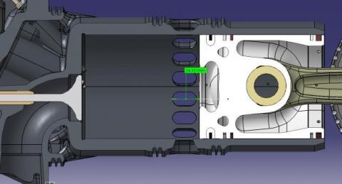
The proposed 2-Stroke engine adopts a Uniflow scavenging system, shown in Figure 1, with 2 exhaust poppet valves on the cylinder head, and a set of inlet ports along the cylinder liner.
This design permits to optimize the in-cylinder turbulence, by means of a proper design of the inlet ports, imparting a swirling motion to the charge entering the cylinder [14-16]. Differently from a 4-Stroke engine, where the dependence of Swirl Ratio on operating conditions is relatively weak, in a 2-Stroke this parameter is controlled by engine speed and by the pressure ratio across the cylinder [17]. Therefore, the design of the scavenge ports was aimed to get a Swirl Ratio between 1.5 and 2.0 for the operating conditions of major interest (high speed, full load): this level of turbulence is able to support an efficient combustion process, as demonstrated by the CFD-3D combustion simulations and the experiments carried out so far.
Another fundamental aspect to be considered in the design of inlet ports is the mixing between fresh charge and exhaust gas: the stronger is the swirl intensity, the higher is the mixing rate and the flow losses through the ports (thus, the worse is the scavenging process). A trade-off among these conflicting requirements was found with the support of several CFD-3D simulations (not presented in this paper for the sake of brevity).
Combustion mainly occurs within the axisymmetric piston bowl, whose design is identical to a 4-Stroke engine. Also, the injector (not visible in Figure 1) is located in a quite conventional position, between the two exhaust valves and almost coincident with the cylinder axis. All the CFD-3D combustion simulations performed for this project show no relevant difference from a 4-Stroke cycle, when considering the same mass of injected fuel and the same composition of the charge. However, for the choice of the injector nozzle design, the specific operating conditions of the 2-Stroke aircraft engine - quite different from the ones occurring in a standard automotive 4-Stroke diesel - should be considered. Therefore, the optimum nozzle geometry of GF56, defined with the support of CFD-3D analyses, is different from that of a 4-Stroke automotive diesel engine, delivering the same maximum brake power. In particular, nozzle holes are smaller, for the following reasons: 1) fuel mass flow rates are lower, due to the double cycle frequency; 2) maximum engine speed is lower, then more time is available for introducing the fuel within the cylinder; 3) small holes enhance atomization, then air-fuel mixing, and may prevent wall impingement (shorter penetration) even when using high injection pressures.
In order to minimize the weight of the engine, cylinder liners are not completely surrounded by a water jacket: their cooling is partly provided by the fresh charge flowing in the air chest, before entering the cylinders through the inlet ports. The only drawback of this solution, that gives a fundamental contribution to the lightness of the engine, is the deformation of the liner, that must be carefully controlled in order to prevent leakages between piston and liner.
Another critical aspect is the cooling of the cylinder head, because of the double frequency of the 2-Stroke cycle. However, this aspect is compensated by the relatively low maximum engine speed, and by the lower combustion temperature, due to the dilution of the charge, as well as to the higher ratio of trapped air to fuel.
Figure 1. The scavenging and combustion system
The analyzed 2-Stroke engine has been modeled using the CFD-1D software GT-Power [18]. The main differences from the modeling of a standard 4-Stroke turbocharged engine are:
The first two issues are addressed by running a CFD-3D analysis of the scavenging process, at different operating conditions. The methodology is comprehensively described in previous papers [19].
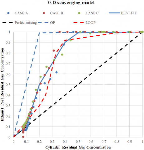
Figure 2 shows the curve (BEST FIT) selected for representing the scavenging patterns in GT-Power simulations. It is observed that the quality of the process is quite good. Until one half of the cylinder mass is emptied through the exhaust valves, no fresh charge is lost: therefore, the first part of scavenging is equivalent to an ideal process (perfect displacement). In the second part, some air is by-passing the cylinder, but the trapping efficiency remains always higher than in a perfect mixing process (dashed line in Figure 2). As an example, when the cylinder mass is made up of 20% of residual gas and 80% of fresh charge, the exhaust flow contains 50% of residual gas, 2.5 times more than in the perfect mixing mode.
Figure 2. Zero-dimensional scavenging model derived from the results of a set of CFD-3D simulations. The Opposed Piston (OP) and the LOOP results come from a previous study [19]
In order to put these results in a relative context, the scavenging curves calculated in a previous study [19] for an Opposed Piston (OP) engine and a Loop Scavenged (LOOP) engine are also shown in Figure 2. The OP design enables an almost ideal process, while the Loop design (with piston-controlled scavenge and exhaust ports) is normally less efficient. The Uniflow system developed in this project is always better than an optimized Loop design, and not too far from the OP curve (best-in-class).
The 1D engine model has been calibrated by comparison with a comprehensive set of experimental data, measured at the dynamometer bench on the last version of the engine (November 2019). The agreement between simulation and experiments is very good (maximum error on brake parameters lower than 2%, maximum error on average pressures and temperatures: 5%); the comparison is not shown for the sake of brevity.
The calibrated engine model was used to address the choice of some fundamental design parameters, in particular:
The main goal of the optimization is to achieve the performance targets (in particular the rated power of 360 HP at 2400 rpm, sea level) minimizing fuel consumption and complying with all the design constraints. As far as the last ones are concerned, the most important are:
It is observed that the flow balance among cylinders is often critical in 2-Stroke engines, much more than in 4-Strokes. This trend was experimentally observed also in the first prototypes of GF56. The main reason is the absence of the exhaust and intake strokes, so that the gas exchange process is fully governed by the fluid-dynamic conditions across each cylinder, that may be not uniform. Therefore, the maximum care was devoted to design equivalent flow paths throughout the cylinders, as well as to guarantee the symmetry between the two banks of cylinders. From this point of view, the use of a single turbocharger represents an advantage.
A fundamental help to the regularity and uniformity of the flow comes from the Roots superchargers, installed after the intercooler and blowing directly into the air chests: even if the engine can work without them in most operating conditions, it does not appear convenient to remove or by-pass them. Obviously, the power adsorbed by these machines should be minimized, selecting a proper transmission ratio.
Another peculiarity of the analyzed engine is the need of operating above sea level, up to an altitude of 18,000 ft. Therefore, a further goal of the project is to guarantee a brake power higher than 270 HP (75% of rated power) at this maximum altitude. This target is of fundamental importance for the choice of the turbocharger size and of the transmission ratio of the superchargers. As altitude increases, air density decreases: keeping constant engine speed and air-fuel ratio, without any control on the turbine (no waste-gate), the operating point on the compressor map is shifted toward higher turbocharger speeds and higher pressure ratios. When the choke limit is reached, fuel rate (then brake power) must be reduced, for avoiding turbocharger failures (over-speeding). Therefore, to guarantee a good engine-turbocharger matching, the operating points on the compressor map at sea level should stay far from the choke curve, allowing the points to shift within the map, as altitude increases. In other words, the higher is the altitude to be reached, the bigger is the swallowing capacity required by the turbocharger. The supercharger helps to maintain high performance at high altitude: the higher is its speed, the better. Unfortunately, also the parasitic losses of the blower increases, so that high performance at high altitude are balanced by high fuel consumption at sea level. The final configuration of the engine is the result of a long iterative process, mainly driven by CFD-1D simulation but also including the contribution of other CAE tools, as well as of practical experience on similar projects. Therefore, it would be impossible in this paper to review the whole process: only the final results of the optimization will be presented in the following section.
In this section, the main performance parameters of the optimized engine, predicted by CFD-1D simulations, are presented. The operating conditions correspond to a dynamometer bench test, at full load, sea level. Engine speed varies between 1400 and 2600 rpm, by step of 200 rpm; the mass flow rate of fuel is controlled by the trapped air-fuel ratio at smoke limit. The last parameter, derives from CFD-3D combustion simulations and it is confirmed by the simulation of experimental tests carried out by using the calibrated GT-Power model. It should be noted that, in 2-Stroke diesel engines it is very hard to get an experimental measure of the trapped air-fuel ratio from the analysis of exhaust gas composition, since it is almost impossible to tell the portion of air bypassing the cylinder during the scavenging process.
As far as the intercooler is concerned, it is supposed to adopt the same system employed during the experimental tests, at the CMD’s dynamometer bed. In this way, no modification to the calibrated CFD-1D engine model is needed.
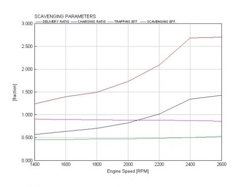
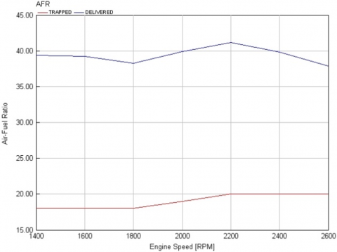
The parameters related to the gas exchange process are first presented in Figures 3-6: average pressures across the cylinders (i.e. at the scavenge ports and at the exhaust valves); pressure ratio across the supercharger; delivery ratio (corresponding to volumetric efficiency in a 4-Stroke engine); trapping efficiency (ratio of the trapped air mass at exhaust valve closure to the delivered air mass); charging ratio (ratio of trapped air mass to the theoretical air mass, i.e. the product of ambient air density to engine displacement); scavenging efficiency (ratio of trapped air mass to trapped cylinder mass); delivered and trapped air-fuel ratio.
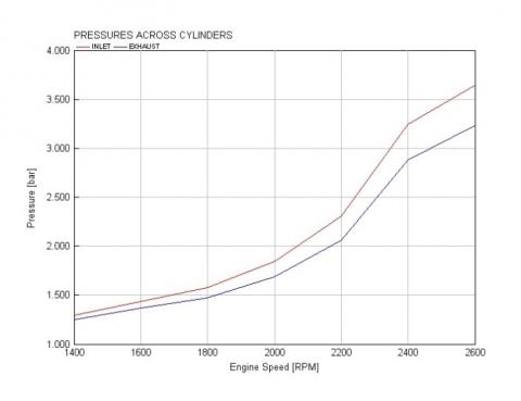
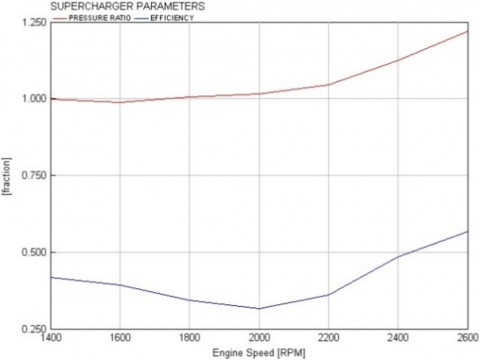
Figure 3 shows the pressure differential across the cylinders, depending on the turbocharger balance (compressor outlet and turbine inlet pressure), as well as on the contribution of the supercharger (visible in Figure 4). Differently from a 4-Stroke, the airflow rate delivered by the engine is mainly controlled by this pressure differential, in combination with cylinder permeability. It is observed that the supercharger provides a pressure ratio higher than 1 (up to 1.2) only at medium-high speeds (>2000 rpm), while at lower speeds it is almost “transparent” (but it helps to keep the flow regular, stabilizing the oscillations of turbocharger speed). Even when the supercharger plays an active role on scavenging at sea level, its efficiency remains quite low. However, it should be considered that this component is designed to be light and compact, more than efficient; moreover, as altitude increases, its efficiency improves.
The pressures shown in Figure 3 determine the delivery ratios presented in Figure 5. However, the air available for combustion is much lower than the delivered mass: trapping efficiency is about 0.5, meaning that one half of the air pumped into cylinders goes to the exhaust.
Figure 3. GF56 engine, intake and exhaust average pressures predicted by CFD-1D simulation at full load (smoke limit), sea level
Figure 4. GF56 engine, pressure ratio and efficiency of the supercharger, predicted by CFD-1D simulation at full load (smoke limit), sea level
Figure 5. GF56 engine, scavenging parameters at full load, sea level, predicted by CFD-1D simulation at full load (smoke limit), sea level
Figure 6. GF56 engine, Air-Fuel ratios predicted by CFD-1D simulation at full load (smoke limit), sea level
At rated power (2400 rpm), charging ratio is about 1.35, while the scavenging efficiency is 87%. Considering that the trapped air-fuel ratio is 20 (see Figure 6), the conditions of the charge at maximum power for GF56 correspond to a medium load and speed operating point in a standard automotive 4-Stroke engine, with 13% of EGR.
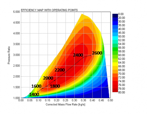
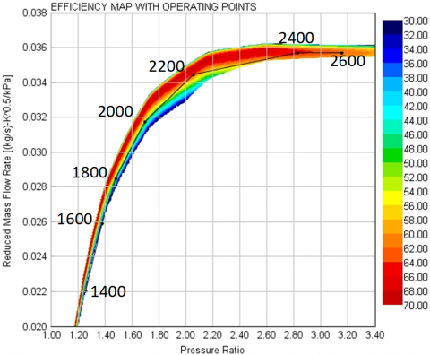
The operations of both compressor and turbine may be analyzed by plotting the operating points on the respective maps: Figure 7 shows the compressor, Figure 8 the turbine. Both graphs demonstrate that the matching between engine and turbocharger is very good: all the operating points of interest fall in regions of high efficiency.
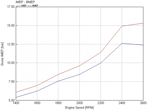
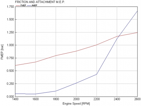
Another fundamental set of characteristic parameters is represented by Mean Effective Pressures (MEPs): Indicated MEP (IMEP), Brake MEP (BMEP), Friction MEP (FMEP), and Attachment MEP (AMEP). The last one is the ratio of the work adsorbed by the attached supercharger to engine displacement. It corresponds to the Pumping MEP of 4-Stroke engines, since it represents the energy spent for the replacement of the spent charge.
As expected, at maximum power the values of IMEP and BMEP are quite low for a turbocharged engine (15 and 12.5 bar, respectively), and comparable to the typical values of a naturally aspirated 4-Stroke SI engine. The value of AMEP at 2400 rpm (1.5 bar) is similar to the one observed at full load, high speed on a 4-Stroke CI marine engine, equipped with a turbine controlled by a waste-gate valve [19]. The values of FMEPs are definitely lower than those typically found on any 4-Stroke engine, at same mean piston speed and in-cylinder peak pressure.
Figure 7. GF56 engine, operating points at full load (smoke limit), sea level, plotted on the efficiency map of the compressor (one bank)
Figure 8. GF56 engine, operating points at full load (smoke limit), sea level, plotted on the efficiency map of the turbine (one bank)
Figure 9. GF56 engine, IMEP and BMEP predicted by CFD-1D simulation at full load (smoke limit), sea level
Figure 10. GF56 engine, FMEP and AMEP predicted by CFD-1D simulation at full load (smoke limit), sea level
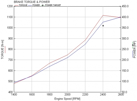
Figure 11. GF56 engine, brake torque and power predicted by CFD-1D simulation at full load (smoke limit), sea level
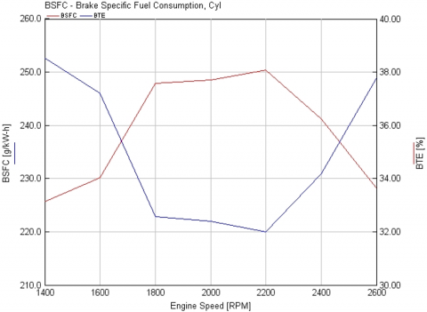
Figure 12. GF56 engine, BSFC and BTE predicted by CFD-1D simulation at full load (smoke limit), sea level
Finally, the standard brake parameters, torque, power, BSFC and Brake Thermal Efficiency (BTE), are presented in Figures 11 and 12. It may be noticed that the power target at 2400 rpm is exceeded of about 16 HP (+4%), and further 24 HP can be obtained increasing the propeller speed up to 2600 rpm. Obviously, the power excess can be used also for down-speeding: the ensuing advantages would be a reduction of fuel consumption, as well as a lower propeller noise. A slight improvement of BTE is also expected with the optimization of the injection strategy (the CFD-1D model does not consider the final evolution of the combustion system).
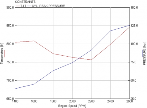
Figure 13 presents a check on two fundamental constraints, for engine reliability and durability: Turbine Inlet Temperature (TIT) and cylinder peak pressure; the former must be below 1073 K (800 °C), the latter under 130 bar. Both constraints are fully complied. It is observed that the turbine inlet temperature is much lower than the limit, because of the dilution with fresh air, during the scavenging process.
Figure 13. GF56 engine, Turbine Inlet Temperature (TIT) and Cylinder Peak Pressure predicted by CFD-1D simulation at full load (smoke limit), sea level
The paper reviews the design and performance of a new 360HP 2-Stroke 5.6L 6-cylinder CI aircraft engine, running on diesel and jet A-1 fuels. The scavenging is of the Uniflow type, with exhaust poppet valves on the cylinder head, and a set of piston-controlled inlet ports on the cylinder liner. The 2-stage supercharging system is made up of one or two turbochargers (on parallel), intercooler and two Roots superchargers (also on parallel). For the thermo-fluid-dynamic aspects, the development was fully supported by CFD-1D and 3D simulations, integrated by several experimental activities on physical prototypes.
In the last configuration, the most interesting technical features of this engine can be summarized as follows:
At the moment of writing this paper, the engine is in its final stage of development, and it has still to receive certification. For this reason, it is not possible to make a direct comparison with a certified 4-Stroke CI aircraft engine. However, the study demonstrates that 2-Stroke CI engines can be a very interesting option, for both the replacement of old 4-Stroke petrol engines in existing aircraft and as original equipment in new ones.
|
2S |
2-Stroke |
|
4S |
4-Stroke |
|
AMEP |
Attachment Mean Effective Pressure |
|
BMEP |
Brake Mean Effective Pressure |
|
BSFC |
Brake Specific Fuel Consumption |
|
BTE |
Brake Thermal Efficiency |
|
CFD |
Computational Fluid Dynamic |
|
CI |
Compression Ignition |
|
FMEP |
Friction Mean Effective Pressure |
|
IDI |
Indirect Injection |
|
IMEP |
Indicated Mean Effective Pressure |
|
PMEP |
Pumping Mean Effective Pressure |
|
SI |
Spark Ignition |
|
TIT |
Turbine Inlet Temperature |
[1] Continental Motor Website. (2020). http://www.continentaldiesel.com/typo3/fileadmin/_centurion/news/newsuploads/186/PR_170725_TC%20CD-300_EN_final.pdf, accessed on March 2020.
[2] Rotax Website. (2020). https://www.flyrotax.com/products.html.
[3] Lycoming Website. (2020). https://www.lycoming.com/engines
[4] Heywood, J.B., Sher, E. (1999). Two-Stroke Cycle Engine: Its Development, Operation and Design. Taylor & Francis.
[5] Heywood, J.B. (1988). Internal Combustion Engine Fundamentals. McGraw-Hill.
[6] Pohorelsky, L., Brynych, P., Macek, J., Vallaude, P.Y., Ricaud, J.C., Obernesser, P., Tribotté, P. (2012). Air system conception for a downsized two-stroke diesel engine (No. 2012-01-0831). SAE Technical Paper. https://doi.org/10.4271/2012-01-0831
[7] Brouwers, A.P. (1980). 150 and 300 kW lightweight diesel aircraft engine study (Vol. 3260). National Aeronatucs and Space Administration, Scientific and Technical Information Office.
[8] Mattarelli, E., Paltrinieri, F., Perini, F., Rinaldini, C.A., Wilksch, M. (2010). 2-Stroke diesel engine for light aircraft: IDI vs. DI combustion systems (No. 2010-01-2147). SAE Technical Paper. https://doi.org/10.4271/2010-01-2147
[9] Mattarelli, E., Rinaldini, C.A., Wilksch, M. (2011). 2-stroke high speed diesel engines for light aircraft. SAE International Journal of Engines, 4(2): 2338-2360. https://doi.org/10.4271/2011-24-0089
[10] DeltaHawk Fuel Jet Engines Website: https://deltahawk.com/engine-specifications, accessed on March 2020.
[11] Zoche Website. (2020). http://www.zoche.de/zoche_brochure.pdf.
[12] Carlucci, A.P., Ficarella, A., Laforgia, D., Renna, A. (2015). Supercharging system behavior for high altitude operation of an aircraft 2-stroke Diesel engine. Energy Conversion and Management, 101: 470-480. https://doi.org/10.1016/j.enconman.2015.06.009
[13] Carlucci, A.P., Ficarella, A., Trullo, G. (2016). Performance optimization of a Two-Stroke supercharged diesel engine for aircraft propulsion. Energy Conversion and Management, 122: 279-289. https://doi.org/10.1016/j.enconman.2016.05.077
[14] Knoll, R. (1998). AVL two-stroke diesel engine (No. 981038). SAE Technical Paper. https://doi.org/10.4271/981038
[15] Ravi, M.R., Marathe, A.G. (1992). Effect of port sizes and timings on the scavenging characteristics of a uniflow scavenged engine. Journal of Engines, 101(3): 1571-1589.
[16] Tamamidis, P., Assanis, D.N. (1993). Optimization of inlet port design in a uniflow-scavenged engine using a 3-D turbulent flow code. Journal of Engines, 102(3): 1621-1633.
[17] Ravi, M.R., Marathe, A.G. (1992). Effect of inlet and exhaust pressures on the scavenging characteristics of a carbureted uniflow scavenged engine (No. 920840). SAE Technical Paper.
[18] Gamma Technologies, GT-Power User’s Manual, Version 2016.
[19] Mattarelli, E., Rinaldini, C.A., Savioli, T., Warey, A., Gopalakrishnan, V., Potter, M. (2018). An Innovative Hybrid Powertrain for Small and Medium Boats (No. 2018-01-0373). SAE Technical Paper. https://doi.org/10.4271/2018-01-0373