Guilin Yang* | Bokai Feng
© 2020 IIETA. This article is published by IIETA and is licensed under the CC BY 4.0 license (http://creativecommons.org/licenses/by/4.0/).
OPEN ACCESS
The abrasive water jet (AWJ) is an immensely popular tool to machine hard-to-cut materials. Taking the surface roughness as the metric of cutting quality, this paper designs and implements an orthogonal experiment for the AWJ cutting of carbon fiber reinforced plastic (CFRP), a lightweight composite widely adopted for high-precision applications. Four factors that affect cutting quality, namely, target distance, pump pressure, nozzle traversal speed, and abradant flow rate, were selected, and divided into five levels for the orthogonal design. Since different factors differ in the value on the same level, the orthogonal design was improved by the quasi-level method. The results of the orthogonal experiment show that the nozzle traversal speed exerted the greatest effect on cutting quality, followed in turn by pump pressure, abradant flow rate, and target distance; the optimal cutting quality could be achieved at the target distance of 7mm, the abradant flow rate of 5g/s, the pump pressure of 340MPa, and the nozzle traversal speed of 200mm/min. The research results provide experimental evidence for high-quality AWJ cutting of the CFRP.
carbon fiber reinforced plastic (CFRP), abrasive water jet (AWJ) cutting, surface quality, orthogonal experiment
Carbon fiber reinforced plastic (CFRP) is a lightweight composite with high specific strength and specific modulus. Thanks to its resistance to fatigue, corrosion, and high temperature, the CFRP has been widely adopted for high-precision applications, namely, aerospace, aviation, and military. However, microstructure failure might occur if the CFRP is machined by the traditional method, because the phase distribution of this advanced composite is discontinuous, heterogeneous, and anisotropic. After all, the lamellar carbon crystals in carbon fiber might cross each other, instead of always being regular. The failure probability is increased by the complexity and thermal effect of the traditional machining method, which involves such processes as fiber fracturing, matrix cracking, and separation between fiber and matrix [1].
The abrasive water jet (AWJ) provides a clean and efficient tool for cold cutting of the CFRP. The AWJ technology is universal, flexible, and highly efficient. The ultra-high pressure AWJ exerts a small force on the CFRP surface, without inducing any thermal effect. In this way, the AWJ cutting will not change the stress-strain or material properties of the CFRP [2-4]. There are many important parameters of the AWJ cutting, including but not limited to jet pressure, nozzle diameter, cutting speed, and cutting angle. These parameters directly bear on the cutting efficiency and effect, and the surface roughness of the target [5-8]. Owing to the unique features of the CFRP, the AWJ cutting of the CFRP follows a quite different law from that of the AWJ cutting of conventional materials.
Many scholars have probed into the AWJ cutting of the CFRP. For instance, Unde et al. [9] found that the cutting angle is clearly affected by the target distance and feed speed, while the surface roughness of the target is obviously influenced by fiber angle and jet pressure. Thongkaew et al. [10] conducted AWJ drilling experiments on the CFRP, and concluded that the drilling quality is negatively correlated with feed speed and drilling diameter, but not greatly affected by jet pressure or abradant flow rate. Kumaran et al. [11] experimentally demonstrated that the surface roughness of the CFRP has a positive correlation with the cutting speed and target distance, and a negative correlation with jet pressure; the experimental results were in line with the surface roughness predicted by adaptive neuro-fuzzy inference system (ANFIS). Ramraji et al. [12] studied how the content and particle size of abradant affect the erosion process of the CFRP. Through numerical analysis, Wang et al. [13] discovered that coarse particles have better cutting effect than fine particles. Tripathi et al. [14] explored the mechanism of high-pressure AWJ cutting of the CFRP, analyzed the causes of delamination failure, and evaluated the effects of multiple parameters (e.g. jet pressure, cutting speed, target distance, and abradant flow rate) on cutting quality.
To sum up, the previous studies have shown that the cutting quality and depth of the AWJ on the CFRP depend heavily on process parameters like jet pressure, cutting speed, and abradant flow rate. However, there is little report on the surface morphology or roughness on the cutting plane [15-19]. To make up the gap, this paper carries out orthogonal experiment to disclose the impacts of the AWJ cutting speed and the CFRP thickness on the surface roughness on the cutting plane, and to reveal the variation of surface roughness with cutting depths.
2.1 Influencing factors of the CFRP failure
The failure mode of the CFRP carries a variety of complex morphological features. Being a composite, the CFRP consists of two materials: the matrix and the reinforced fiber. The latter has relatively high strain rate. The difference in strain rate has a significant effect on the impact performance of the CFRP [20]. The impact performance is also affected by its interfacial properties and the difference in impact energy. The mechanical properties of reinforced fiber, as the main load bearer, have a decisive effect on the impact resistance of the CFRP.
In the CFRP, the matrix has a much lower strength and stiffness than reinforced fiber. Despite that, the many properties (e.g. interfacial strength, compressive strength, and cracking resistance) of the CFRP depend on the matrix properties. When the CFRP is under external impact, the damage area and degree of compression will be determined by the toughness of the matrix. Lots of shock energy will be absorbed, if the matrix is relatively tough. Moreover, a tougher matrix means a smaller modulus of the CFRP.
In general, the matrix cannot absorb as much energy as the reinforced fiber and the delamination process [21]. The delamination is dependent on the interfacial strength, which hinges on the failure mode. Subjected to external impact, the CFRP may absorb energy through tensile failure, compressive failure, or shear failure. Therefore, the interfacial strength exerts an important impact on the impact resistance of the CFRP.
The previous literature has shown that, if it is below the initial failure threshold, the impact energy will be absorbed mainly by the delamination inside the matrix; if it is above that threshold, the impact energy will be absorbed mainly by the reinforced fiber. In the latter case, the reinforced fiber is pulled out or broken, releasing the absorbed energy. Much more energy is absorbed by reinforced fiber than the matrix.
Besides the impact resistance, the failure of the CFRP is also affected by external factors. For example, the impact failure directly depends on the magnitude of the impact energy, which in turn depends on the mass source and impact speed [22]. The impact resistance of the CFRP is sensitive to impact speed. The impact speed has a positive correlation with the strain rate of reinforced fiber.
2.2 Failure process of the CFRP
There are four basic failure modes of the CFRP, such as fiber fracturing, matrix cracking, separation between fiber and matrix, and delamination [23]. These failure modes may appear alone or together, depending on factors like fiber orientation, fiber arrangement, matrix load, etc. The propagation direction of the failure is often related to the orientation and sequence of reinforced fibers in the CFRP.
Once the source of impact energy touches the CFRP, compressive stress will be applied on the positive surface of the CFRP, and most shock waves will propagate downward in the thickness direction. After reaching the back surface, the shock waves will be reflected, creating a tensile stress on that surface. Under a high impact energy, both positive and back surfaces of the CFRP will be stressed. Delamination will occur, when the tensile stress surpasses the shear strength of the interface. This phenomenon will be aggravated by the interfacial stress induced by local bending.
Each material has a specific threshold of impact failure, which is known as the impact threshold [24-26]. If the impact energy is below this threshold, the material will not be affected, not to mention impact failure. If the impact energy gradually rises above the threshold, the material will start to suffer from damages so insignificant as to be unobservable on the surface. However, delamination has already taken hold inside the material. Further growth of the impact energy will bring visible cracks in the matrix along the fiber direction on the back side of the material, and the delamination will worsen inside the material.
With the continuous growth of impact energy, the material surface will be damaged visibly: impact pits could appear under local depression of fiber or matrix; sometimes, matrix cracks could be observed directly on the impact surface along the fiber direction. The latter mainly depends on the matrix toughness, fracture strain of reinforced fiber, and the thickness of the laminate [27]. At this time, serious matrix cracking, and even fiber fractures, will be visible on the back side; the delaminated area will be much larger than the area of surface damage; the mechanical properties of the material will be severely undermined [28-30].
If the impact energy is sufficiently large, the material will be penetrated through by cracks, showing a completely new failure state. Because of the fast motion of the impact source, the energy wave cannot propagate within the penetrated material, and not much impact energy could be absorbed. As a result, the penetrated material will not exhibit serious delamination, and the delaminated area will be smaller than that before penetration.
3.1 Instruments and materials
3.1.1 Instruments
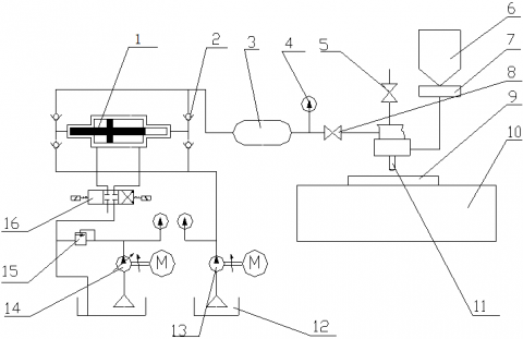
The AWJ cutting test system consists of a JJ-I water jet cutting machine, an ultrahigh voltage (UHV) mainframe, an operation console, and an abradant supply equipment. The nozzle, overall structure, and performance indices of the water jet cutting machine are displayed in Figure 1, Figure 2, and Table 1, respectively.
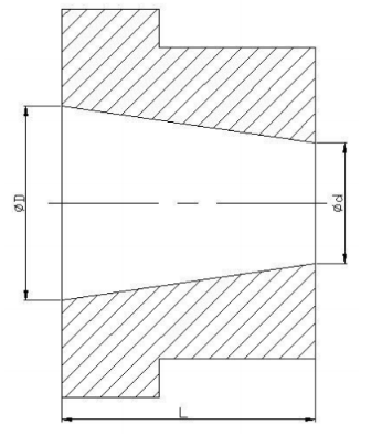
Figure 1. The nozzle structure (D=1mm; L=1.3mm; d=0.6 mm)
Figure 2. The structure of water jet cutting machine
(1. Supercharger; 2. Check valve; 3. High pressure vessel; 4. Pressure gage; 5. Gas control valve; 6. Sand head; 7. Sand valve 8. High pressure valve; 9. Workpiece; 10. 2D cutting platform; Cutting head 12. Water tank; 13. Booster pump; 14. Ram pump; 15. Overflow valve; 16. Selector valve)
Figure 3. The roughness tester
Table 1. Main performance indices of the AWJ cutting test system
|
Index |
Value |
|
Maximum pressure (MPa) |
500 |
|
Maximum water flow (L/min) |
4 |
|
Mainframe power (kW) |
37 |
|
Maximum range of cutting plane (L×W) (mm) |
2,000×1,250 |
During the experiments, the hydraulic system of the UHV mainframe pumped filtered and softened water to boost the pressure in the supercharger. The water was then pumped through the pipeline to the cutting head on the water jet cutting machine. Meanwhile, the abradant supply equipment transported the abradant to the cutting head, which cut the CFRP specimen along the preset path. The instrument functions and cutting parameters were controlled and adjusted automatically by the operation console.
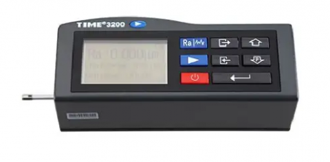
The surface roughness of the specimen was measured by a TR200 roughness tester (Figure 3).
3.1.2 Abradant
Garnet is the most widely used abradant in the AWJ cutting. This abradant is moderate in hardness, stable in physical-chemical properties, and uniform in particle size and crystal form. In our experiment, the parameters of the selected garnet abradant are as follows: particle size, 80 mesh; Mohs hardness, 7; density, 3.9-4.1g/cm3. On the microscale, the abradant is highly granular with irregular angles.
3.1.3 Specimen preparation
The workpiece of our experiment is 20mm-thick CFRP sheets. Each CFRP sheet contains 12 layers of T300 reinforced fiber. The photo and properties of the CFRP sheets are presented in Figure 4 and Table 2, respectively.
Figure 4. The photo of the CFRP sheet
Table 2. The properties of the CFRP sheets
|
Parameter |
Value |
|
Type |
T300 |
|
Density (g/cm3) |
4 |
|
Tensile strength (MPa) |
3.53 |
|
Tensile modulus (MPa) |
230 |
|
Elongation at break (%) |
1.5 |
|
Mass fraction (%) |
92.5 |
|
Fiber diameter (μm) |
7 |
3.2 Experimental design
The cutting performance of the AWJ is greatly affected by various process parameters. The change of any parameter will induce the variation of the surface roughness on the cutting plane. If multiple parameters change together, the variation of surface roughness will become extremely complicated. Our experiment mainly aims to disclose how the surface roughness is affected by four process parameters: target distance, pump pressure, nozzle traversal speed, and abradant flow rate.
Table 3. The improved experimental design
|
Test number |
Factors |
|||
|
A |
B |
C |
D |
|
|
1 |
1 |
1 |
1 |
1 |
|
2 |
1 |
2 |
2 |
2 |
|
3 |
1 |
3 |
3 |
3 |
|
4 |
1 |
4 |
4 |
4 |
|
5 |
1 |
5 |
5 |
5 |
|
6 |
2 |
1 |
2 |
4 |
|
7 |
2 |
2 |
3 |
5 |
|
8 |
2 |
3 |
4 |
1 |
|
9 |
2 |
4 |
5 |
2 |
|
10 |
2 |
5 |
1 |
3 |
|
11 |
3 |
1 |
3 |
5 |
|
12 |
3 |
2 |
4 |
1 |
|
13 |
3 |
3 |
5 |
2 |
|
14 |
3 |
4 |
1 |
3 |
|
15 |
3 |
5 |
2 |
4 |
|
16 |
4 |
1 |
4 |
2 |
|
17 |
4 |
2 |
5 |
3 |
|
18 |
4 |
3 |
1 |
4 |
|
19 |
4 |
4 |
2 |
5 |
|
20 |
4 |
5 |
3 |
1 |
|
21 |
5 |
1 |
5 |
3 |
|
22 |
5 |
2 |
1 |
4 |
|
23 |
5 |
3 |
2 |
5 |
|
24 |
5 |
4 |
3 |
1 |
|
25 |
5 |
5 |
4 |
2 |
(1) Target distance (factor A) was controlled within 3-20mm, and divided into five levels: 5mm (level 1), 7mm (level 2), 10mm (level 3), 12mm (level 4), and 15mm (level 5).
(2) Pump pressure (factor B) was controlled within 0-380MPa, and divided into five levels: 200MPa (level 1), 260MPa (level 2), 280MPa (level 3), 300MPa (level 4), and 340MPa (level 5).
(3) Nozzle traversal speed (factor C) was controlled within 0-1,000mm/min, and divided into five levels: 100mm/min (level 1), 200mm/min (level 2), 300mm/min (level 3), 400mm/min (level 4), and 500mm/min (level 5).
(4) Abradant flow rate (factor D) was controlled with 0-20g/s, and divided into five levels: 3g/s (level 1), 4g/s (level 2), 5g/s (level 3), 6g/s (level 4), and 7g/s (level 5).
To sum up, our experiment needs to investigate four factors, each of which has 5 levels. There are as many as 625 possible combinations between these factors and levels. Hence, the orthogonal design was adopted for our experiment, because fewer experiments are needed under this design to solve multi-factor and multi-level problems. The orthogonal design uses an orthogonal table with F factors and Q levels, involving Latin squares (L) and a number (M) of horizontal combinations.
With surface roughness as the measurement index, an L25(54) orthogonal table was designed, because the maximum number of horizontal factors is 5, and the total degree of freedom (DOF) of the factors is 16. Since different factors differ in the value on the same level, the orthogonal design was improved by the quasi-level method, a virtual multi-level design that arranges one or more levels of a factor repeatedly. The improved experimental design is described in Table 3.
4.1 Data processing
The surface roughness measured in the orthogonal experiment is listed in Table 4.
Using the SPSS software (significance level: 0.05), the analysis of variance (ANOVA) was performed on the measured results (Table 4) obtained under the experimental design (Table 3). The results of ANOVA are listed in Table 5.
Table 4. The measured results
|
Test number |
Surface roughness (μm) |
Test number |
Surface roughness (μm) |
|
1 |
6.2 |
13 |
2.2 |
|
2 |
5.8 |
14 |
1.6 |
|
3 |
4.2 |
15 |
3.1 |
|
4 |
3.25 |
16 |
5.0 |
|
5 |
1.6 |
17 |
3.8 |
|
6 |
6.1 |
18 |
1.9 |
|
7 |
5.1 |
19 |
2.6 |
|
8 |
2.8 |
20 |
3.7 |
|
9 |
1.5 |
21 |
4.5 |
|
10 |
2.3 |
22 |
3.1 |
|
11 |
5.9 |
23 |
1.3 |
|
12 |
4.3 |
24 |
2.6 |
Table 5. Results of ANOVA
|
|
SST |
df |
MS |
F |
Significance |
|
Target distance |
2715 |
4 |
78.5 |
1.632 |
1.226 |
|
Pump pressure |
2.0×10⁶ |
4 |
10000 |
1.996 |
1.882 |
|
Abradant flow rate |
2,750,000 |
4 |
12.5 |
0.952 |
0.097 |
|
Nozzle traversal speed |
675 |
4 |
125000 |
2.638 |
0.035 |
It can be seen that the significance of nozzle traversal speed was 0.035, smaller than 0.05. This means nozzle traversal speed has a significant effect on surface roughness. Meanwhile, the other three factors have insignificant effects on surface roughness. Judging by the F-statistic, the four factors could be ranked as nozzle transversal speed, pump pressure, abradant flow rate, and target distance in descending order of the effect on surface roughness.
4.2 Data analysis
Through SPSS data processing, the relationship between some factors and cutting quality are plotted as Figures 5-19 based on the mean values of each factor and the surface roughness of the CFRP.
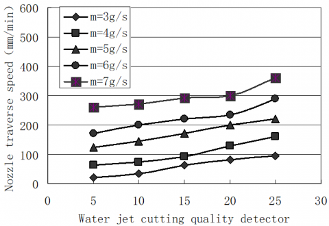
(1) When the target distance was 7 mm, the nozzle traversal speed fell within 100-500mm/min, and the pump pressure fell within 220-340MPa, the optimal cutting quality was achieved at the abradant flow rate of 5 g/s.
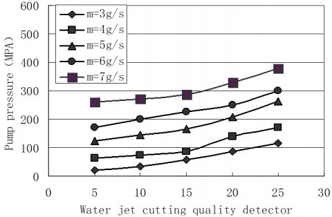
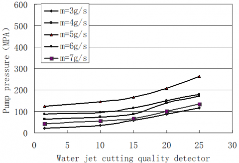
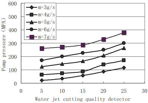
(2) When the target distance was 7 mm, the nozzle traversal speed fell within 100-500mm/min, and the abradant flow rate fell within 3-7g/s, the cutting quality was improved with the growth of pump pressure, and was optimized at the pump pressure of 340MPa.
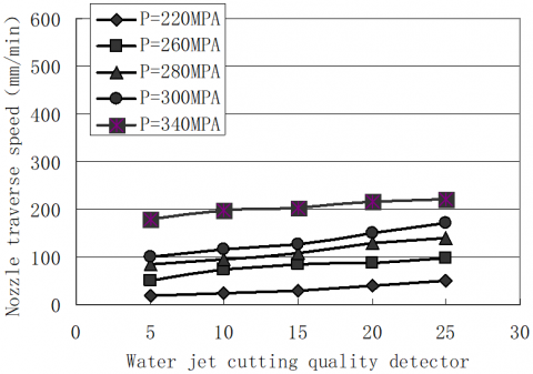
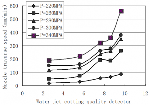
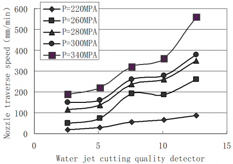
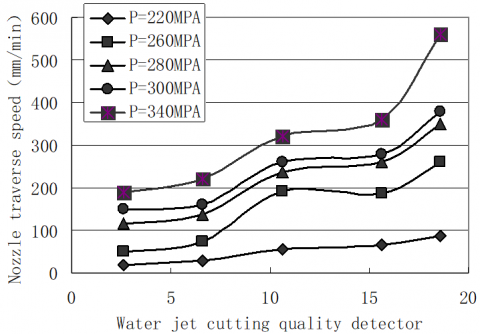
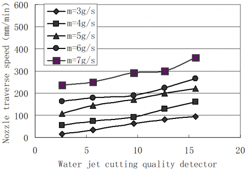
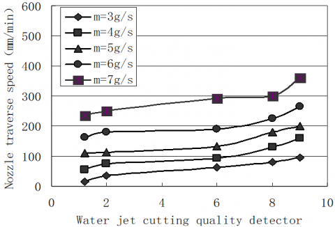
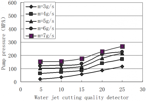
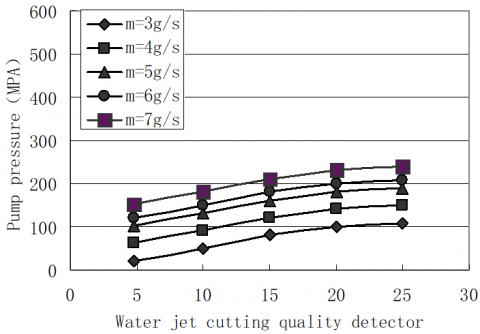
(3) When the target distance was 7 mm, the pump pressure fell within 220-340MPa, and the abradant flow rate fell within 3-7g/s, the optimal cutting quality was achieved at the nozzle traversal speed of 200 mm/min.
Figure 5. Relationship between cutting quality and nozzle traversal speed (target distance: 7mm; abradant flow rate: 3g/s)
Figure 6. Relationship between cutting quality and nozzle traversal speed (target distance: 7mm; abradant flow rate: 4g/s)
Figure 7. Relationship between cutting quality and nozzle traversal speed (target distance: 7mm; abradant flow rate: 5g/s)
Figure 8. Relationship between cutting quality and nozzle traversal speed (target distance: 7mm; abradant flow rate: 6g/s)
Figure 9. Relationship between cutting quality and nozzle traversal speed (target distance: 7mm; abradant flow rate: 7g/s)
Figure 10. Relationship between cutting quality and nozzle traversal speed (target distance: 7mm; pump pressure: 220MPa)
Figure 11. Relationship between cutting quality and nozzle traversal speed (target distance: 7mm; pump pressure: 260MPa)
Figure 12. Relationship between cutting quality and nozzle traversal speed (target distance: 7mm; pump pressure: 280MPa)
Figure 13. Relationship between cutting quality and nozzle traversal speed (target distance: 7mm; pump pressure: 300MPa)
Figure 14. Relationship between cutting quality and nozzle traversal speed (target distance: 7mm; pump pressure: 340MPa)
Figure 15. Relationship between cutting quality and pump pressure (target distance: 7mm; nozzle traversal speed: 100mm/min)
Figure 16. Relationship between cutting quality and pump pressure (target distance: 7mm; nozzle traversal speed: 200mm/min)
Figure 17. Relationship between cutting quality and pump pressure (target distance: 7mm; nozzle traversal speed: 300mm/min)
Figure 18. Relationship between cutting quality and pump pressure (target distance: 7mm; nozzle traversal speed: 400mm/min)
Figure 19. Relationship between cutting quality and pump pressure (target distance: 7mm; nozzle traversal speed: 500mm/min)
Overall, under the target distance of 7mm, the optimal cutting quality could be achieved at the abradant flow rate of 5g/s, the pump pressure of 340MPa, and the nozzle traversal speed of 200mm/min. The nozzle traversal speed exerted the greatest effect on cutting quality, followed in turn by pump pressure, abradant flow rate, and target distance. Nozzle traversal speed, pump pressure, and abradant flow rate are three relatively significant factors affecting the cutting quality.
Through a four-factor, five-level orthogonal experiment, this paper thoroughly explores the effects of target distance, pump pressure, nozzle traversal speed, and abradant flow rate on the quality of the AWJ cutting on the CFRP. The cutting quality was measured by the surface roughness of the CFRP sheet. The main conclusions are as follows:
(1) The four factors, namely, target distance, nozzle traversal speed, pump pressure, and abradant flow rate, had different effects on the cutting quality. The quality of the AWJ cutting on the CFRP is strongly affected by nozzle traversal speed, pump pressure, and abradant flow rate, and slightly affected by target distance.
(2) The optimal parameter settings for the AWJ cutting on the CFRP could be determined as the target distance of 7mm, the abradant flow rate of 5g/s, the pump pressure of 340MPa, and the nozzle traversal speed of 200mm/min.
Our research provides empirical evidence and qualitative data for theoretical and experimental analyses on the AWJ cutting on the CFRP in future.
This work was supported by the University Technological Plan Project of Shandong Province of China (Grant No. J17KA026), and Shandong Province Teaching Reform Project of China (Grant No. C2016M029).
[1] Barsukov, G.V., Zhuravleva, T.A., Kozhus, O.G. (2020). The research and simulation (modeling) of the destruction of a single abrasive particle during waterjet cutting. Materials Science Forum, 989(5940): 235-241. https://doi.org/10.4028/www.scientific.net/MSF.989.235
[2] Kumar, B., Kumari, C., Sharada, M., Mangala, M. (2012). Evaluation of the medical records system in an upcoming teaching hospital a project for improvisation. Journal of Medical Systems, 6(4): 2171-2175. https://doi.org/10.1007/s10916-011-9681-6
[3] Blanco-Montenegro, I., De Ritis, R., Chiappini, M. (2007). Imaging and modelling the subsurface structure of volcanic calderas with high-resolution aeromagnetic data at Vulcano (Aeolian Islands, Italy). Bulletin of Volcanology, 69(6): 643-659. https://doi.org/10.1007/s00170-0 19-03971-0
[4] Schwartzentruber, J., Papini, M., Spelt, J.K. (2018). Characterizing and modelling delamination of carbon-fiber epoxy laminates during abrasive waterjet cutting. Composites Part A: Applied Science and Manufacturing, 112: 299-314. https://doi.org/10.1016/j.compositesa.2018.06.014
[5] Magliaro, J., Altenhof, W. (2020). Mechanical performance and crashworthiness of plates and extrusions subjected to cutting: An overview. Thin-Walled Structures, 148: 106612. https://doi.org/10.1016/j.tws.2020.106612
[6] Díaz-Álvarez, A., Díaz-Álvarez, J., Cantero, J.L., Santiuste, C. (2020). Analysis of orthogonal cutting of biocomposites. Composite Structures, 234: 111734. https://doi.org/10.1016/j.compstruct.2019.111734
[7] Lee, M.H., Yang, W., Chae, N., Choi, S. (2019). Performance assessment of HEPA filter against radioactive aerosols from metal cutting during nuclear decommissioning. Nuclear Engineering and Technology, 52(5): 1043-1050. https://doi.org/10.1016/j.net.2019.10.017
[8] Kitamura, T., Tanaka, R., Yamane, Y., Sekiya, K., Yamada, K. (2020). Performance evaluation method for cutting fluids using cutting force in micro-feed end milling. Precision Engineering, 62: 232-243.
[9] Unde, P.D., Gayakwad, M.D., Patil, N.G., Pawade, R.S., Thakur, D.G., Brahmankar, P.K. (2015). Experimental investigations into abrasive waterjet machining of carbon fiber reinforced plastic. Journal of Composites, 2015: 971596. https://doi.org/10.1155/2015/971596
[10] Thongkaew, K., Wang, J., Yeoh, G.H. (2016). An investigation of hole machining process on a carbon-fiber reinforced plastic sheet by abrasive waterjet. In Advanced Materials Research, 1136: 113-118. https://doi.org/10.4028/www.scientific.net/AMR.1136.113
[11] Kumaran, S.T., Ko, T.J., Kurniawan, R., Li, C., Uthayakumar, M. (2017). ANFIS modeling of surface roughness in abrasive waterjet machining of carbon fiber reinforced plastics. Journal of Mechanical Science and Technology, 31(8): 3949-3954. https://doi.org/10.1007/s12206-017-0741-9
[12] Ramraji, K., Rajkumar, K., Dhananchezian, M., Sabarinathan, P. (2020). Key experimental investigations of cutting dimensionality by abrasive water jet machining on basalt fiber /fly ash reinforced polymer composite. Materials Today: Proceedings, 22(4): 1351-1359. https://doi.org/10.1016/j.matpr.2020.01.428
[13] Wang, J.S., Li, X.H., Yang, L., Lu, Y.Y., Sun, J.J. (2000). Effect of abrasive parameters on cutting efficiency of collimated abrasive water jet. Journal of Hydrodynamics, 15(1): 89-93. https://doi.org/10.3969/j.issn.1000-4874.2000.01.011
[14] Tripathi, D.R., Vachhani, K.H., Kumari, S., Abhishek, K. (2020). Experimental investigation on material removal rate during abrasive water jet machining of GFRP composites. Materials Today: Proceedings, 22(4): 1-4. https://doi.org/10.1016/j.matpr.2020.02.280
[15] Hashish, M. (1989). A model for abrasive-waterjet (AWJ) machining. Journal of Engineering Materials and Technology, 111(2): 154-162. https://doi.org/10.1115/1. 3226448
[16] Cha, Y., Oh, T.M., Cho, G.C. (2020). Effects of Focus Geometry on the Hard Rock-Cutting Performance of an Abrasive Waterjet. Advances in Civil Engineering, 2020: 1650914. https://doi.org/10.1155/2020/1650914
[17] Glechner, T., Hahn, R., Wojcik, T., Holec, D., Kolozsvári, S., Zaid, H., Kodambaka, S., Mayrhofer, P.H., Riedl, H. (2019). Assessment of ductile character in superhard Ta-CN thin films. Acta Materialia, 179: 17-25. https://doi.org/10.1016/j.actamat.2019.08. 015
[18] Fan, X., Li, M.M., Singh, D.J., Jiang, Q., Zheng, W.T. (2015). Identification of a potential superhard compound ReCN. Journal of Alloys and Compounds, 631: 321-327. https://doi.org/10.1016/j.jallcom.2015.01.119
[19] James, B., Pierson, H.A. (2019). Modeling and simulation of industrial waterjet stripping for complex geometries. The International Journal of Advanced Manufacturing Technology, 105(5-6): 2431-2446. https://doi.org/10.1007/s00170-019-04405-7
[20] Latchoumi, T.P., Balamurugan, K., Dinesh, K., Ezhilarasi, T.P. (2019). Particle swarm optimization approach for waterjet cavitation peening. Measurement, 141: 184-189. https://doi.org/10.1016/j.measurement.2019.04.040
[21] Durán-Grados, V., Mejías, J., Musina, L., Moreno-Gutiérrez, J. (2018). The influence of the waterjet propulsion system on the ships' energy consumption and emissions inventories. Science of the Total Environment, 631: 496-509. https://doi.org/10.1016/j.scitotenv.2018.02.291
[22] Sosin, M., Weissler, J. M., Pulcrano, M., Rodriguez, E.D. (2015). Transcartilaginous ear piercing and infectious complications: a systematic review and critical analysis of outcomes. The Laryngoscope, 125(8): 1827-1834. https://doi.org/10.1002/lary.25238
[23] Perianu, I.A., Mitelea, I., Şerban, V.A. (2014). The effect of water pressure variation on cut surfaces quality during abrasive waterjet cutting of austenitic steels. In Advanced Materials Research, 1029(3460): 176-181. https://doi.org/10.4028/www.scientific.net/AMR.1029.176
[24] Dhanawade, A., Kumar, S. (2017). Experimental study of delamination and kerf geometry of carbon epoxy composite machined by abrasive water jet. Journal of Composite Materials, 51(24): 3373-3390. https://doi.org/10.1177/0021998316688950
[25] Yamane, Y., Ryutaro, T., Tadanori, S., Ramirez, I.M., Keiji, Y. (2017). A new quantitative evaluation for characteristic of surface roughness in turning. Precision Engineering, 50: 20-26. https://doi.org/10.1016/j.precisioneng.2017.04.009
[26] Zhang, M., Liu, J., Hu, Z., Zhao, Y. (2018). Experimental and numerical investigation of the responses of scaled tanker side double-hull structures laterally punched by conical and knife edge indenters. Marine Structures, 61: 62-84. https://doi.org/10.1016/j.marstruc.2018.04.006
[27] Boldyrev, I.S. (2018). SPG simulation of free orthogonal cutting for cutting forces prediction. In International Conference on Industrial Engineering, pp. 1695-1700. https://doi.org/10.1016/j.proeng.2017.10.618
[28] Desbiolles, J., Taki, O., Butler, G. (2020). A laboratory evaluation of waterjet cutting of crop residue using the Aqua-Till® liquid coulter. Soil and Tillage Research, 198: 104537. https://doi.org/10.1016/j.still.2019.104537
[29] Aydin, G., Kaya, S., Karakurt, I. (2017). Utilization of solid-cutting waste of granite as an alternative abrasive in abrasive waterjet cutting of marble. Journal of Cleaner Production, 159: 241-247. https://doi.org/10.1016/j.jclepro.2017.04.173
[30] Ishfaq, K., Ahmad Mufti, N., Ahmed, N., Pervaiz, S. (2019). Abrasive waterjet cutting of cladded material: kerf taper and MRR analysis. Materials and Manufacturing Processes, 34(5): 544-553. http://doi.org/10.1080/10426914.2018.1544710