Rassim Younes* | Mohand Amokrane Bradai | Abdelhamid Sadeddine | Youcef Mouadji
© 2020 IIETA. This article is published by IIETA and is licensed under the CC BY 4.0 license (http://creativecommons.org/licenses/by/4.0/).
OPEN ACCESS
Thermally sprayed of X30Cr13 martensitic stainless steel coatings are widely used to reduce degradation of components and structures due to mechanical wear. In this paper, the microstructure and mechanical properties of X30Cr13 coated onto on 35CrMo4 using Wire Arc Spray Process (WASP) are investigated. These coatings were made with to different system bond-coat layer which is constituted by Ni-Al. The microstructure characteristics of the coatings are studied using the combined techniques of X-ray diffraction (XRD), scanning electron microscopy (SEM). Measurements of Vickers hardness was carried out on top of the surface of stainless steel. The scanning electron microscopy presents a dense microstructure of this stainless steel, which had a homogeneous compact lamellae shape with the presence of pores and unmelted particles. The wear resistance of the two systems composite Sub/Bond-Coat/X30Cr13 and Sub/X30Cr13 is affected by sliding velocities under different applied loads. The system composite Sub/X30Cr13exhibits low wear resistance than Sub/Bond-Coat/X30Cr13 coating.
coating, bond-coat, microstructure, tribology, stainless steel
The thermal spraying technics offers the opportunity to realize, on mechanical parts, diversified metallic coatings. These coatings are intended to protect the substrate (surface of the mechanical part) from attacks of various origins: mechanical (wear resistance), thermal (thermal barriers) and chemical (anti-corrosion barrier). Whatever the function of the coating, the morphology of the interface which conditions the adhesion to the substrate and the microstructure of the deposit for better resistance to wear and corrosion are the two fundamental parameters in the determination of the performance of the deposits.
Thermal spraying is a process in which particles are deposited on a substrate [1-5]. Consequently, the spraying technique is a way of generating a ‘stream’ of such particles. Coatings can be formed if the melted fused projectile can deform at the shocks with the substrate. Wire Arc Spray Process (WASP)is one of several technics which consist on being two wires consumable arc electrodes, are drawn from spools and form a liquid droplet due to arc heating [6-10]. The droplet is blown by the atomizing gas. The gas atomizes the molten droplet and propels fine particles towards a substrate. If the wires are made of different metals, a -alloy coating can be produced.
Stainless steels are iron based alloys containing a rate about 13% chromium [11-13]; this oxide film forms protective self-healing, is the main properties why this field have their most important characteristic which is stainlessness. The other owner is a high magnification through a microscope that can be seen as a piece of material is seen. The safe chemical percent composition of the steel and the microstructure can consist of stable phases or ferrite, a mixture of these two elements. Phase martensite formed when some are tempered at high temperature, or a structure hardened by micro -constituents precipitated [14, 15].
The coatings of X30Cr13 are one of most technology that is required as a response to improve the reliability of parts under multiple stresses in manufactories like automotive, food and chemistry [16-18]. Due to their method of production, the microstructure of the sprayed coatings is complex and the properties are dependent on there [19, 20]. The objective of this study is to establish relationships between microstructure and tribological properties.
The present investigation has been conducted to study coatings of stainless-steelX30Cr13 type. These coatings were deposited on a low carbon steel type 35CrMo4 by using a Wire Arc Spray Process (WASP). In this goal, two types of composite system, A and B, have been prepared. The structure and microstructure of coatings were analyzed by scanning electron microscope and X-ray diffraction (XRD). Mechanical properties were studied on hardness test which was also applied on the top of coatings. The tribological behaviour was studied using type of tribometer at different loads for sliding time of 30 minutes in order to evaluate the rate wear under two velocities (0.5 and 1 m/s). This test showed a high relationship with a microstructure and thus allowed to determine the role of microstructural characteristics of composite coating on their tribological properties.
2.1 Preparation of coatings
The substrate used in the present investigation was 35CrMo4 steel with the following nominal chemical composition (Table 1) which’s obtained by using fluorescence X-rays analysis. Before the WASP, the top of surfaces was blasted with alumina particles and cleaned using acetone with an ultrasonic bath. The grit blasted substrates were coated with wire. This wire was continuously melting and compressed air blown directly behind the point of contact.
The wire was sprayed onto grit blasted substrates using an APS technique (model Arc Spray 234) (Figure 1) and the spray input parameters and properties of the used materials are given in Table 2 and Table 3.
Figure 1. Wire Arc Spray Process (WASP)
Table 1. Chemical composition of materials used
|
Materials(%) |
C |
Cr |
Fe |
Al |
Mn |
Ni |
|
35CrMo4 |
0.32 |
0.90 |
Bal |
|
0.90 |
≤ 0.30 |
|
NiAl |
/ |
/ |
/ |
15 |
/ |
75 |
|
X30Cr13 |
0.3 - 0.4 |
12 - 14 |
Bal |
0.04 |
0.35 |
<0.5 |
|
Projection parameters |
Coating |
|
Air pressure in the engine (bars) |
03.8 |
|
Air pressure in the spray nozzle (bars) |
03 |
|
oxygen pressure (bars) |
04,5 |
|
Wire’s speed (mm/s) |
06 |
|
Generator voltage (V) |
35 |
|
Current intensity (A) |
100 |
|
Spray distance (mm) |
140 |
|
Spray angle |
90 |
|
Wire diameter (mm) |
01.6 |
|
Rate of traverse (mm/s) |
66 |
|
covered area (m2/h/0.1 mm) |
08 |
|
deposited weight (g/s) |
01.5 |
|
Properties |
X30Cr13 |
|
Elastic Modulus E (GPa) |
220 |
|
Thermal conductivity[W·m-1·K-1] |
30 |
|
Poisson ratio (ν) |
0.33 |
|
Density ρ (Kg m-3) |
7700 |
|
Tensile strength (GPa) |
600 |
|
Thermal expansion α (10-6 K-1) |
23.7 |
As-received coatings are cross-sectioned, ground using SiC papers with grit sizes down to 2400 and finally polished with 1 µm alumina. Microstructure of the coatings is observed using optical microscopy and scanning electron microscopy (QUANTA 600FEI) The X-rays diffraction patterns were recorded at room temperature with a X'PERT PRO MRD diffractometer of PANalytical equipped with a Cu-anode X-ray tube and a curved graphite monochromator. To improve counting and increase the waves of background ratio, the strong presence of defects in these materials creates a significant background noise, record time of 40 second per angular step of 0.04° over the 30°-120° (2θ) range. The identification of the crystal phases present in the coatings was performed using X'Pert High Score software supported with the ICDD-PDF2 database.
2.3 Vickers hardness investigation
Hardness Investigation as mechanical properties studies of the materials was investigated by a kind of Pyramidal penetrator Vickers test. During the applied mass, the Vickers penetrated through the surface at the same velocity unloading pressure period when the pyramid moved backwards [21]. The indentation procedure consisted of 60 steps, with a waiting period between consecutive steps of 30s according to ASTM 1327 [22]. Hardness test were carried out under indentation 2N loading. An average hardness was calculated from 10 indents per specimen.
Preliminary tests have already been carried out to establish the conditions, tests of profile cross-section microhardness on the transversal part of the samples were carried out by repetitive indentation going from the substrate to the surface of the deposit passing through the interface, every step the value was recorded and calculated on an average basis of 5 measurements.
2.4 Wear resistance performance
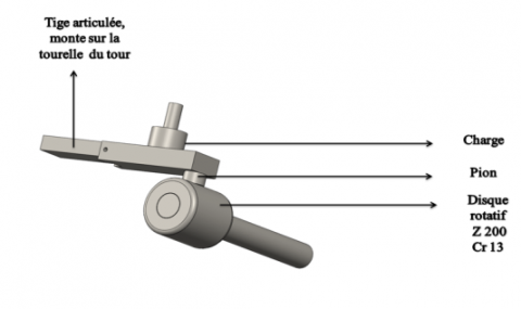
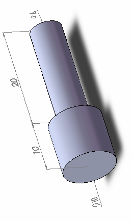
The abrasive wear test was applied out a pin on disc tribo-system (Figure 2-a), the specimen’s dimension was cylindrical pin of 10mm diameter and 15mm length (Figure 2-b). For each test we used new polished samples in order to have efficient results. The pin-on-disc contact tests were performed under different loads (5, 10, 15, 20 and 30 N) with a siding distance of 900 m and 1800m, sliding speed of 0.5 m/s and 1m/s. A sintered steel disc type X200Cr12 was employed as the counter body with a new disc being used for each test. The wear behaviour of coatings in dry parameter, and the test was applied without any grass or oil. The wears were determined by weighting each sample before and after the test. The weight losses which occurred on the top of coating were calculated using electronic weighing balance. The wear rate is calculated using the following equation:
$K_{v}=\frac{\Delta m}{N_{c}}$ (1)
Kv: wear rate. (mg/m)
Δm: weight loss. (mg)
NC: number of cycles. (m)
a)
b)
Figure 2. Schematic image of: a)- pin-on-disc test, b)-samples
3.1 Microstructure characterization
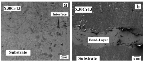
The SEM observations of the coatings shown in Figures 3a and 3b illustrate the morphologies of system composite 1 and system composite 2 of stainless steel coating obtained by arc wire spray process.
Figure 3. Microstructure of composite system: a) Sub/Coating X30Cr13, b) Sub/Bond-coat/ Coating X30Cr13
The microstructural observations of the composite system 1 carried out with the Ni-Al sub-layer showed the good adhesion between the two interfaces Substrate / Sub-layer NiAl and Sub-layer NiAl / deposit (Figure 3-b). We note also that the presence of the bond-layer decreases the porosity rate [23]. This observation illustrates the importance of this bond-layer improve the adhesion between the coatings and the substrate. However, the absence of the sub-layer in composite system 2 seems not to improve adhesion of the coating due to the presence of decohesion along the substrate / deposit interface. A crack initiates at the notch, first in the coating and then propagates symmetrically in the coating–substrate interface. This crack is subject to constant moment conditions and propagates in steady state conditions.
3.2 Structural examination
The X-ray patterns of coatings stainless steel are depicted in Figure 4. The identification of the crystalline phases is made by comparison between the lines observed and those of the suitable phases contained in the data base PDF2
Figure 4. X-ray pattern of coating X30Cr13
Figure 4 shows the diffractogram X-ray patterns obtained exclusively from the coating X30Cr13. It revealed that the observed peaks are characteristic of solid solution composed mainly by (Fe, Cr) structure with a lattice parameter of 2,8673 A° the formation of only carbides of chrome such as CCr, dealing with the large statistical variations of composition. The formation of these carbides is made possible as a result of the larger content of carbon. We also note the presence of a large fraction of oxides type Fe3O4 [22].
3.3 Vickers microhardness
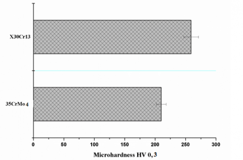
Vickers Micro Hardness measurements were recorded on the coating and substrate (Figure 5). It was performed on the top of surface coatings X30Cr13 using a ZHV10 microhardness tester under 300 g and a dwell time of 40 s. An average is due from seven indents.
These tests revealed that the micro hardness of the stainless steel coating X30Cr13 is higher than substrate 35CrMo4 (260 ± 16 HV0,3 against about 210± 12HV0,3). This gap can be due to the influence of the porosity ratio. The micro hardness of stainless steel coatings depends essentially on their chemical composition. Figure 6 depicted profil of microhardness of the two systems composites. It’s revealed that the system composite sub/bond-coat/X30Cr13 have a highest microhardness. We note also that the biggest value of Vickers microhardness is on the top of surface. It is clearly due to the formation of oxides which caused by contacting with air.
Figure 5. Microhardness of different materials used. Longitudinal errors bars show maximum and minimum microhardness
Figure 6. Profil Microhardness of different materials used
3.4 Tribology test
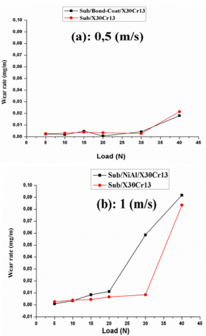
Figure 7. Effect of velocities on the wear rate of the coatings
The two systems composites were performed on pin-on-disc tribometer with two different sliding velocity 0.5 m/s and 1m/s under different loads in order to determinate their effect on mechanical properties. The Figure 7 shows the variation of the wear rate of the two systems as function load.
Figure 7 revealed the wear rates of the two systems composites: Sub/Bond-Coat/X30Cr13and Sub/X30Cr13 as function of applied load. These two composites systems produced have nearly the same wear resistance under the two sliding velocities (0.5 and 1 m/s).Whereas, under high load, when the sliding speed is go up from 0.5 to 1 m/s, the wear rate is the higher (0.02 under 0.5m/s against 0.08 under 1m/s).
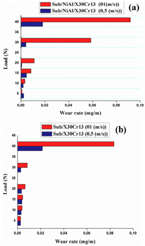
Figure 8. Effect of load on the wear rate of the coatings
Figure 8 shows a comparative study of the wear rate between the two systems composites: sub/bond-coat/X30Cr13 and sub/X30Cr13 versus the abrasive load. The wear rate of X30Cr13 is linearly increased according to the sliding load and appears to be very slightly. However, the stainless coating Sub/X30Cr13 exhibits remarkably bad wear rate than sub/bond-coat/X30Cr13 coating. It can be due to of the presence of carbides chrome such as CCr and the presence of oxides type Fe3O4.
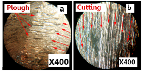
Figure 9. Wear track of different samples: a- 0.5 m/s, b- 1 m/s
Figure 9 showed optical images of samples that have been tested under different load along with their height profiles. For each parameter, the depicted picture was taken between the 15 and 18 mm locations measured from the wear starting position. The abrasive of the surface coated samples contains cracks, spalling and delamination. Also, plastic deformation at the side walls of the wear samples under different scan is seen for all samples. The ridges are uniform and narrow across the scratch length. In contrast to the high load, samples ridges are thick and non-uniform due to presumably to the high work hardening rate. One of the explanations for this behavior is that the hardness of the carbides, in particular the chromium carbides, decreases considerably under a load of 30N and a sliding speed of 1m/s. In this dry wear test, the two factors caused plough of the top of the surface due to abrasive wear as seen on our stainless steel coating. We remark also light and continuous asperities, it’s probably caused by particles have sharp wedges, by sliding led to increased wear rate in the initial stage of friction. Small particles cannot be instantly eliminated from a comparatively wide contact area, for purely geometrical reasons and they stick to the track surface.
The present paper has summarized the effect of bond-layer on the wear resistance of a martensitic stainless steel coating obtained by wire arc spray. It can be concluded that:
- The diffraction X-ray patterns of the coating X30Cr13 revealed the presence of solid solution composed mainly by (Fe, Cr) structure with a lattice parameter of 2,8673 A° that corresponds to the bcc structure and the formation of only carbides of chrome such as CCr.
- Microhardness tests revealed that the hardness of stainless steel coating X30Cr13 is higher than Substrate about 260 ± 66 HV0.2for X30Cr13 against about 210± 25HV0.2 for substrate 35CrMo4.The microhardness of stainless steel coatings depends on this chemical composition. The coating X30Cr13 with bond-coat have homogenous increasing more than the coating without bond coat.
-The wear rate of the two systems composite sub/bond-coat/X30Cr13and Sub/X30Cr13 versus the abrasive load. The wear rate of X30Cr13 is linearly increased according to the sliding load and appears to be very slightly. The system composite sub/bond-coat/X30Cr13 has an average of 0.005 mg/min until 30 N at 0.5m/s. however, the same system composite sub/bond-coat/X30Cr13 start increasing wear rate at 20N under 1m/s and reach 0.06 mg/min (6 more time under 0.5m/s). The difference of wear rate as function of load reached nearly 25% between systems composite 1 against system composite 2.
[1] Mouadji, Y., Bradai, M.A., Younes, R., Sad-eddine, A., Benabbas, A. (2018). Influence of heat treatment on microstructure and tribological properties of flame spraying Fe-Ni-Al alloy coating. Journal of Central South University, 25: 473–481. https://doi.org/10.1007/s11771-018-3751-6
[2] Baiamonte, L., Marra, F., Gazzola, S., Giovanetto, P., Bartuli, C., Valente, T., Pulci, G. (2016). Thermal sprayed coatings for hot corrosion protection of exhaust valves in naval diesel engines. Surface and Coatings Technology, 295: 78-87. https://doi.org/10.1016/j.surfcoat.2015.10.072
[3] Peat, T., Galloway, A.M., Toumpis, A.I., Harvey, D. (2016). Evaluation of the synergistic erosion-corrosion behaviour of HVOF thermal spray coatings. Surface and Coatings Technology, 299: 37-48. https://doi.org/10.1016/j.surfcoat.2016.04.072
[4] Younes, R., Bradai, M.A., Sadeddine, A., Mouadji, Y., Bilek, A., Benabbas, A. (2017). Microstructural and tribological properties of Al2O3-13pctTiO2 thermal spray coatings deposited by flame spraying. Metallurgical and Materials Transactions B, 46(5): 2394-2403. https://doi.org/10.1007/s11663-015-0412-0
[5] Pawłowski, L. (2013). Strategic oxides for thermal spraying: problems of availability and evolution of prices. Surface and Coatings Technology, 220: 14-19. https://doi.org/10.1016/j.surfcoat.2012.04.096
[6] Salavati, S., Coyle, T.W., Mostaghimi, J. (2016). Twin wire arc spray process modification for production of porous metallic coatings. Surface and Coatings Technology, 286: 16-24. https://doi.org/10.1016/j.surfcoat.2015.12.004
[7] Tillmann, W., Vogli, E., Abdulgader, M., Gurris, M., Kuzmin, D., Turek, S. (2011). Particle behavior during the Arc spraying process with cored wires. Journal of Thermal Spray Technology, 17: 966-973. https://doi.org/10.1007/s11666-008-9272-3
[8] Reddy, S., Shekar, V.T. (2013). Rationale behind ‘stainless steel super structure’ for buses. SAE International Journal of Materials and Manufacturing, Ashok Leyland, Ltd. https://doi.org/10.4271/2013-01-2418
[9] Asim, K., Hosford, W., Pan, J., Hong, S., Weil, K.S. (2009). Mechanical behavior and failure mechanism of Nb-clad stainless steel sheets. SAE International Journal of Materials and Manufacturing, 2(1): 547-554. https://doi.org/10.4271/2009-01-1393
[10] Zhang, X., Wang, Z.H., Lin, J.R., Zhou, Z.H. (2015). A study on high temperature oxidation behavior of high-velocity arc sprayed Fe-based coatings. Surface and Coatings Technology, 283: 255-261. https://doi.org/10.1016/j.surfcoat.2015.10.067
[11] Lv, J.L., Liang, T.X., Wang, C. (2016). Surface enriched molybdenum enhancing the corrosion resistance of 316L stainless steel. Materials Letters, 171: 38-41. https://doi.org/10.1016/j.matlet.2016.01.153
[12] Gardner, L., Bu, Y., Francis, P., Baddoo, N.R., Cashell, K.A., McCann, F. (2016). Elevated temperature material properties of stainless steel reinforcing bar. Construction and Building Materials, 114: 977-997. https://doi.org/10.1016/j.conbuildmat.2016.04.009
[13] Jewkes, J., Sawers, D., Stillerman, R. (1969). Stainless Steels. In: The Sources of Invention. Palgrave Macmillan, London. https://doi.org/10.1007/978-1-349-00015-9_45
[14] Gatto, M.F., Pedicini, R., Carbone, A., Saccà, A., Matera, F., Gatto, I. (2018). Study and development of innovative materials for hydrogen storage activity. Revue des Composites et des Matériaux Avancés, 28(3): 323-332. https://doi.org/10.3166/RCMA.28.323-332
[15] Xi, S., Zhang, Y.Z., Ji, Y., Zhu, Y.L., Liu, Y., Yang, Y.T., Yu, M.L. (2018). Integrated growth of Si-O-C nanosheets on the surface of carbon microstructure with the aid of carbon nanotubes. Revue des Composites et des Matériaux Avancés, 28(2): 289-298. https://doi.org/10.3166/RCMA.28.289-298
[16] Fukaya, M., Ariyoshi, H., Komori, T. (2007). Development of ferritic stainless steel sheet for weight sensor substrate. SAE International Journal of Materials and Manufacturing. https://doi.org/10.4271/2007-01-0353
[17] Clarke, K.D., Comstock, R.J., Mataya, M.C., Matlock, D.K., Speer, J.G., Martins, G.P. (2003). The effect of strain rate on the sheet tensile properties and formability of ferritic stainless steels. SAE International Journal of Materials and Manufacturing. https://doi.org/10.4271/2003-01-0526
[18] Nordberg, H. (2005). Fatigue properties of stainless steel lap joints. Spot welded, adhesive bonded, weldbonded, laser welded and clinched joints ff stainless steel sheets-A Review of their fatigue properties. SAE International Journal of Materials and Manufacturing. https://doi.org/10.4271/2005-01-1324
[19] Ono, N., Takahashi, A., Tanoue, T., Sakamoto, S., Matsuhashi, R., Kikuchi, M. (2005). Application of ferritic stainless steel to automotive fuel system parts. SAE International Journal of Materials and Manufacturing. https://doi.org/10.4271/2005-01-1335
[20] Xu, J., Wu, P., Ye, E.C., Yuan, B.F., Feng, Y.Q. (2016). Metal oxides in sample pretreatment. TrAC Trends in Analytical Chemistry, 80: 41-56. https://doi.org/10.1016/j.trac.2016.02.027
[21] Rassim, Y., Amokrane, B.M., Abdelhamid, S., Youcef, M., Ali, B., Abderrahim, B. (2016). Effect of TiO2 and ZrO2 reinforcements on properties of Al2O3 coatings fabricated by thermal flame spraying. Transactions of Nonferrous Metals Society of China, 26(5): 1345-1352. https://doi.org/10.1016/S1003-6326(16)64237-1
[22] ASTM C1327-15. (2019). Standard Test Method for Vickers Indentation Hardness of Advanced Ceramics, ASTM International, West Conshohocken, PA. https://doi.org/10.1520/C1327-15R19
[23] Gantchenko, V., Renard, J. (2017). Characterization of an adhesive bonding. Arcan-Mines test and fracture mechanics results. Revue des Composites et des Matériaux Avancés, 27(3-4): 319-334. https://doi.org/10.3166/rcma.2017.00019