Dinesh Kumar* | Gurpreet Singh Sokhal | Pankaj Sharma
OPEN ACCESS
Main objective behind this work is to study and analyze the performance of copper-oxide nanofluids with water as base fluid in the flat tube bent through 90⁰ and inlet flow temperature of 40 ℃. The simulation has been carried out using Finite volume method under Reynolds number existing between 1000-5000 and volume concentrations between 0.1 % v/v–0.4 % v/v. Performance of flat tube bent at 90⁰ was compared with performance of straight flat tube under same conditions. The various thermo-physical properties i.e. density, thermal conductivity, viscosity and specific heat capacity has been determined with well-developed models of each presented during previous studies carried out in the field of nanofluids. It was observed during this study that heat performance of nanofluids under different volume concentrations between 0.1 % to 0.4 % v/v of nanoparticles is better than that of base fluids and also increased by almost 19-20 % due to presence of bend in between flat tube. The pressure drop is also increased by with use of nanofluids. The study also proves that use of nanofluids can play very important role in decreasing overall size of heat transfer systems.
radiator, heat transfer coefficient, pressure drop, Nusselt number, friction factor
Over last two or three decades nanofluids have been one of the most influential areas of research. Heat and mass transfer has been most common application of nanofluids. Due to increase in demand for high power production, conventional fluids have become obsolete and requirement of new medium for heat and mass transfer was felt. Basically, nanofluids are colloidal solution of nanoparticle (size less than 100 nm) having high thermal conductivity into base fluid like water and ethylene glycol. This concept of colloidal solution was first introduced by Maxwell [1]. Maxwell used various small particles (not nano-sized) collided into fluid for his study and provided a relation for thermal conductivity. Later in 90’s Choi [2] introduced the term nanofluids as he used nanoparticle instead of normal particles used by Maxwell. For last two decades, commercial and industrial uses of nanofluids have been somewhat limited to only few research purposes around the world. Higher production cost and unavailability of efficient manufacturing techniques were main reasons for this limited use of nanofluids. But with time and various researches being conducted in this field various industries have now started to move into this field and conduct various researches according to their requirement. Automobile industry is one such industry which have very high requirement for heat transfer or cooling devices due to increasing power requirement and in order to decrease the size of cooling device. Various studies have been conducted for studying flow of different type of nanofluids under different geometric configurations of tube i.e. circular cross-sectioned tube, flat tube, and elliptical cross-sectioned tube.
Almost every study conducted after introduction of nanofluids terminology have reported significant amount of enhancement in performance of conventional heat transfer fluids [3-8]. Heris et al. [9] reported in their study of Al2O3/water nanofluids flowing through circular tube that heat transfer coefficient increased with increase in volume concentration of nanoparticle from 0.2 % to 2.5 % with Reynolds number varying in between 700 and 2050. Fotukian and Esfahany [10] revealed that pressure drop is increased when volume concentration increases from 0.03 to 0.135 % under highly turbulent conditions with Reynolds number existing in between 6000 and 31000 for circular cross-sectioned tube.
Namburu et al. [11] have reported increase of 35 % in Nusselt number due to addition of 6 % volume concentration of CuO nanoparticle. Base fluid used in this study was mixture of water and ethylene glycol under turbulent flow regime in circular tube treated with wall condition as constant heat flux. Elias et al. [12] studied impact of Al2O3 nanoparticle on the thermo-physical properties of conventional coolant in radiator and reported that thermal conductivity increases while density and viscosity decreases due to addition of nanoparticle. Vajjha et al. [13] reported that average heat transfer coefficient increases by 2.17 times base fluid for Al2O3 and CuO nanofluids when Reynolds number increased from 3000 to 8000. Base fluid used was 60: 40 mixtures of ethylene glycol and water for this analysis.
Peyghambarzadeh et al. [14] experimentally studied performance of Al2O3/water (20 nm) nanofluids under highly turbulent region in automobile radiator having elliptical cross-sectioned tubes. Results obtained in this study clearly shows 30-45 % increase in heat transfer coefficient compared with base fluid i.e. water. Further enhancement of Nusselt number obtained was 6 %, when inlet temperature of fluid was changed from 37 ℃ to 49 ℃. Delavari and Hashemabadi [15] evaluated various CFD simulation results and studied enhancement in heat transfer enhancement for flow of Al2O3 / water and Al2O3 ethylene glycol in flat tube of a radiator. Results obtained in this paper show that local friction coefficient increase with increase in concentration, also increase in Nusselt number with rising volume concentrations and Reynolds number for both nanofluids.
Zhao et al. [16] also conducted numerical analysis of Al2O3/water nanofluids in flat tube and reported that when liquid inlet velocity through tube is increased enhancement percentage diminishes at all concentrations. Particle volume concentration between 1 to 6 % was analysed throughout study. It was also found that lower particle diameter results in higher heat transfer enhancement. Leyong et al. [17] have suggested that addition of 2 % CuO nanoparticle in ethylene glycol will give us 18.7 % reduction in frontal area of radiator. Heat transfer performance of radiator is found to improve by 42 % to 45.2 % when Reynolds number for outside air flow was varied from 4000 to 6000. Elsebay et al. [18] also carried out a numerical study on resizing the flat tube with Al2O3 and CuO nanofluids and reported that size of flat tube can be reduced with use of nanofluids for same heating load.
Nassan and Heris [19] observed that convective heat transfer coefficient shows higher enhancement in CuO/water as compared to Al2O3/water in laminar region having Reynolds number between 660 and 2050 at similar volume concentration. Square cross-sectioned duct was used as test section during this work. In another study, Das et al. [20] reported that temperature conditions have significant amount of impact on the enhancement of thermal conductivity along with nanoparticle concentration. Nieh et al. [21] reported in his study that heat dissipation capacity of TiO2/water nanofluids is greater than Al2O3/water nanofluids under laminar condition. From studies conducted above it can be concluded that heat transfer capability of system increases with volume concentrations as well as Reynolds number.
From above studies it can be clearly seen that most of works that have been done in the field of nanofluids exists in straight tube configurations for various cross sectional areas such as square, circular, elliptical. While there are some works related to study of circular cross-sectioned tube bent at different angles, number of works on flat tube containing bend are still limited in numbers. Main reason behind choosing this problem for study is the fact shown in studies above that heat transfer increases with increase in Reynolds number or turbulence. Presence of bend section will result in higher particle turbulence in the region which can result in better performance. Main objective of this study is to evaluate the impact of 90⁰ bend provided in flat tube configuration on performance of CuO nanofluids flowing through tube. This study is conducted using finite volume approach under Reynolds number between 1000-5000 with volume concentrations of CuO nanofluids varying between 0.1-0.4 % v/v.
The flat tube of radiator has high surface to cross section area ratio in comparison with circular tube i.e. improvement in heat transfer performance. The flat tube with 90⁰ bend is reported to have major (D) and minor (d) diameters. Length of flat tube is kept 0.310 m with bend existing at the centre of geometry. Thickness at bending portion is assumed to be uniform as modelled in the geometry. Geometric configuration of the domain used in this study is clearly shown in Figure 1.
As hydraulic diameter depends completely upon the wetted perimeter and surface area of tube, the hydraulic-diameter of flat-tube was determined with the help of Eq. (1) presented below. In this study hydraulic diameter is calculated to be 0.00535 m.
$D_{h}=\frac{4 \times\left[(\pi / 4) d^{2}+(D-d) \times d\right]}{\pi \times d+2 \times(D-d)}$ (1)
Figure 1. Schematic diagram of tube domain
2.1 Governing equations
The fluid model used in this study is considered Newtonian and incompressible in nature. The fluid is considered homogenous in nature due to small volume concentration and negligible nanoparticle size. The velocity of air flowing over the plate and ambient temperature was assumed to be constant. Under the above conditions, the problem was solved numerically. ANSYS-fluent 14.5 and the conservation Eq. (2), (3) and (4) were used for CFD analysis of problem.
Continuity equation:
$\nabla V=0$ (2)
Energy equation:
$\rho_{n f} C_{p n f}(\nabla V) T=k_{n f} \nabla^{2} T V$ (3)
Momentum equation:
$\rho_{n f}(\nabla V) V=-\nabla P+\left(\mu_{i f}+\mu^{t}\right) \nabla^{2} V$ (4)
2.2 Thermo-physical data
Before moving on to numerical analysis of given problem it is important to calculate thermo-physical properties of the nanofluids. Various studies have been done previously to obtain desired relations to calculate various properties like thermal conductivity, dynamic viscosity, specific heat and density.
The thermal conductivity of nanofluids is calculated by using Hamilton–Crosser (1959) equation shown in Eq. (5) which is as follows:
$\frac{k_{n f}}{k_{b f}}=\frac{k_{p}+(n-1) k_{b f}-\varphi(n-1)\left(k_{b f}-k_{p}\right)}{k_{p}+(n-1) k_{b f}-\varphi\left(k_{b f}-k_{p}\right)}$ (5)
The expression employed to determine the dynamic-viscosity of nanofluids reported by Einstein (1906) is generally in Eq. (6) as follows:
$\mu_{n f}=\mu_{b f}(1+2.5 \phi)$ (6)
Specific heat of nanofluids is determined from Xuan and Rotzel (2000) relation as provided in the Eq. (7)
$\left(c_{p} \rho\right)_{n f}=\varphi\left(\rho c_{p}\right)_{n p}+(1-\varphi)\left(\rho c_{p}\right)_{b f}$ (7)
Pak and Choi (1998) relation as shown in Eq. (8) is found to give results close to actual measured values. Therefore, this relation is used in present study to get measure values of density:
$\rho_{n f}=(1-\varphi) \rho_{b f}+\varphi \rho_{m p}$ (8)
2.3 Boundary conditions
Various boundary conditions for numerical analysis are provided in the Table 1.
Table 1. Operating parameters
|
Parameter |
Range |
|
Base fluid |
Water |
|
Nanoparticle |
Copper oxide |
|
Volume concentration |
0.1 – 0.4 % v/v |
|
Reynolds number |
1000 – 5000 |
|
Fluid inlet temperature |
40 oC |
The inlet is considered as inlet velocity and for turbulent flow turbulence intensity is 10 %.
The surface is with constant convection coefficient 150 W/m2.K and free air stream temperature 30 ℃.
The outlet is considered as pressure outlet.
The simulation is carried out with finite volume method.
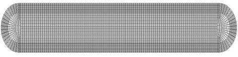
Figure 2. Meshing profile used in tube domain
Meshing profile used in this problem is clearly shown in Figure 2. Mesh is kept fine in outer region of tube as well as in bending section to ensure higher degree of accuracy in solution. In order to optimize the number of elements present in the domain and to decrease the computation time, the mesh independence test was performed. For this, 4 different mesh sizes were generated for discretization. Water as the main fluid with Reynolds number 1000 and fluid-inlet temperature of 40 ℃ is considered for the mesh independence test. The Table 2 shown comprises various element combinations used and results obtained at every combination. The velocity and temperature of grid 3 has a very less difference when compared with results of grid 1, 2 and 4 in spite of the increased number of elements which results in higher computational time. Therefore, the grid 3 is most suitable among all grids provided above to continue in further numerical simulations. To verify the first and second order upwind schemes, two more simulations were run and results were then compared. The results obtained during simulations are provided in Table 3.
Table 2. Mesh independence results
|
Series |
Grid |
Maximum velocity (m/s) |
Maximum temperature (K) |
|
1. |
190x100x62 |
0.2031972 |
310.8012 |
|
2. |
180 x 100 x62 |
0.20327 |
310.800 |
|
3. |
160x100x60 |
0.20346 |
310.798 |
|
4. |
160x95x60 |
0.200238 |
310.6744 |
Table 3. Results for selection of order of upwind scheme method
|
Axial location |
Parameter |
First order upwind |
Second order upwind |
Percentage difference |
|
Z=0.155m |
Temperature (K) |
310.9893 |
310.8199 |
0.1694 |
|
Z=0.155m |
Velocity (m/s) |
0.2019087 |
0.200684 |
0.0012247 |
It is clearly seen from the Table 3 that there is appreciable change in the temperature results for second order upwind method. Since second order upwind technique is more accurate, therefore the second order upwind scheme is used to proceed with further simulations.
Table 4. Effect of gravity on results
|
Series |
Parameter |
With gravity |
Without gravity |
|
1. |
Temperature (K) |
310.8098 |
310.8199 |
|
2. |
Velocity (m/s) |
0.20297 |
0.200684 |
In order to evaluate effect of gravity on the results of numerical analysis two more simulations were run with gravity consideration as well as without gravity consideration; details of which are shown in Table 4. Direction of gravity force was kept in the direction of fluid flow at inlet. From results it is clear that effect of gravity on results of simulations is very small. Further simulations can be carried out without any gravity considerations in order to reduce computational time.
4.1 Data processing
The following Eq. (9) is used to calculate the Reynolds number.
$\operatorname{Re}=\frac{\rho_{n f} \times v \times D_{h}}{\mu_{n f}}$ (9)
The Nusselt number is obtained by use of following Eq. (10):
$N u=\frac{h \times D_{h}}{k}$ (10)
The friction factor was calculated using Eq. (11) as follows:
$f=\frac{2 \times D_{h} \times \Delta P}{\rho \times v^{2} \times L}$ (11)
4.2 Heat transfer performance
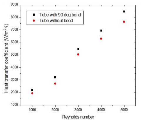
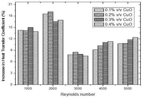
Heat transfer performance of nanofluids is evaluated in present study under different nanoparticle concentrations and different Reynolds number at fluid inlet temperature of 40℃. Each parameter has a significant impact on the performance of nanofluids flowing through tube bent at 90⁰. Heat transfer performance of nanofluids improved with increasing nanoparticle volume concentration. This improvement in heat transfer upon use of nanofluids exists due to greater thermal conductivity of nanofluids compared to base fluid. But, thermal conductivity is not only factor in enhancing heat transfer performance as other factors like chaotic motion of nanofluids particles, energy interaction between nanofluids particles dispersed in base fluid and viscosity change due to migration of nanoparticles. Heat transfer coefficient is found to increase with the rise in volume concentrations of nanofluids from 0.1 % to 0.4 % and with increase in Reynolds number from 1000 to 5000 as shown in the Figure 3. Increase in Reynolds number causes higher turbulence in fluid particles and decreases the thickness of thermal boundary layer formed with wall, which results in higher heat transfer coefficient. At fixed Reynolds number 5000, improvement of 13 %, 10 %, 8 % and 5 % from base fluid was seen in heat transfer coefficient at 0.4 %, 0.3 %, 0.2 % and 0.1 % volume concentration respectively. Maximum heat transfer coefficient 8836.494 W/m2K is obtained at volume concentration 0.4 % and Reynolds number 5000 with almost 13 % increase from base fluid. On the other hand; under the Reynolds number 1000, enhancement of 12 %, 9 %, 8 % and 7 % from base fluid was seen in heat transfer coefficient at volume concentrations 0.4 %, 0.3 %, 0.2 % and 0.1 % respectively. Minimum heat transfer coefficient 2139.60 W/m2 K is reported at volume concentration 0.1 % and Reynolds number 1000 with almost 7 % increase from base fluid. When compared with heat transfer coefficient of straight flat tube (without any bend) having same dimensional parameters like overall length, thickness and width; heat transfer coefficient due to bending of tube is noticed to have increased around 7 %-19 %. Maximum enhancement of 18 %, 19 %, 16 % and 17 % is obtained at Reynolds number 2000 under different nanoparticle concentrations 0.1 %, 0.2 %, 0.3 % and 0.4 % respectively. Maximum rise in heat transfer coefficient is observed at 0.2 % v/v at Reynolds number of 2000 as shown in Figure 4. Minimum 7.69 %, 8.49 %, 7.94 % and 7.5 % increase in heat transfer coefficient is noted under Reynolds number of 3000 at different concentrations 0.1 %, 0.2 %, 0.3 % and 0.4 % respectively. Figure 5 shows increase in heat transfer coefficient with respect to straight flat tube under different volume concentrations and Reynolds number.
Figure 3. Variations in heat transfer coefficient (W/m2 K) along with rising Reynolds number under different volume concentrations
Figure 4. Comparison in heat transfer coefficient for straight flat tube and tube containing 90 ⁰ bend at 0.2 %v/v concentration under Reynolds number 2000
Figure 5. Percentage increase in heat transfer coefficient due to inclusion of 90 ⁰ bend under different Reynolds number and nanoparticle concentrations
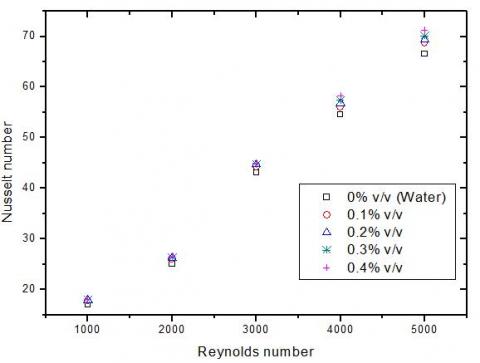
Nusselt number gives better view on heat transfer performance as it gives interrelation between thermal conductivity (k) and heat transfer coefficient (h). Variations in Nusselt number at different nanoparticle concentrations under Reynolds number varying from 1000 to 5000 is shown in Figure 6. Nusselt number increases upon increasing volume concentration from 0.1 % to 0.4 % and also upon increasing Reynolds number from 1000 to 5000. As the nanoparticle concentrations increased from 0 % v/v to 0.4 % v/v, the Nusselt number was enhanced by almost 7%. Maximum enhancement of 3 %, 4 %, 5 % and 7 % occurred at volume concentrations of 0.1 %, 0.2 %, 0.3 % and 0.4 % under Reynolds number 5000. Minimum enhancements of almost 2 %, 3 %, 3 % and 4 % are observed at different volume concentrations 0.1 %, 0.2 %, 0.3 % and 0.4 % under Reynolds number 3000.
Figure 6. Variations in Nusselt number with change in Reynolds number under different nanoparticle concentrations
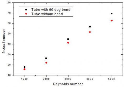
Figure 7. Comparison in Nusselt number obtained for straight flat tube and tube containing 90 ⁰ bend at 0.2 %v/v concentrations under Reynolds number 2000
Figure 8. Percentage increase in Nusselt number due to presence of 90⁰bend under different Reynolds number and volume concentrations
On comparing the Nusselt number of flow through tube bend at 90 ⁰ with that of straight flat tube, it is seen that Nusselt number of bent tube increases by at least 8 %. Maximum amount of increase (almost 20 %) is reported at volume concentration of 0.2 % and Reynolds number of 2000 as shown in Figure 7. Minimum increase of 8 % is noted at 0.1 % v/v at Reynolds number of 3000. Increase in heat transfer coefficient and Nusselt number upon inclusion of bend could perhaps be attributed to presence of higher turbulent intensity at bend section of tube. Upon analyzing Figure 5 and Figure 8 it can be clearly seen that amount of enhancement in heat transfer performance of bent tube in laminar flow region is much higher than turbulent flow region.
4.3 Fluid flow performance
In the practical application of nanofluids, along with the heat transfer performance estimation, the pressure drop is also important. The pressure drop is mainly dependent on viscosity, density and Reynolds number. Figure 9 clearly shows the variation in pressure drop with in a pipe having 90⁰bend with Reynolds number and various nanoparticle concentrations. The pressure drop increases with rise in Reynolds number as well as increase in nanoparticle concentration. Increase in viscosity of base fluid and increase in chaotic behaviour of base fluid due to higher volume concentrations of CuO might be responsible for this increase in pressure drop. The pressure drop is seen to get increased by almost 14 % with the addition of 0.1 % v/v concentration of nanoparticle and increases up to 36 % on addition of 0.4 % v/v concentration of nanoparticle.
Figure 9. Variation in pressure drop (Pa) with an increasing Reynolds number and different concentrations from 0.1 % to 0.4 %
Pressure drop is noticed to have decreased when the flat tube is bent at 90 ⁰. Decrease of pressure drop in bent tube increases with rising Reynolds number. The maximum decrease of almost 15 % compared to the tube without bend is obtained at Reynolds number of 5000 and volume concentrations of 0.4 % v/v as shown in Figure 10. Minimum decrease of less than 1 % is noted at 0.1 % volume concentration and Reynolds number 2000 which is too small. At low Reynolds number, no significant variation in pressure drop is reported. When higher Reynolds number is used this change in pressure drop performance can be clearly seen. This trend was almost similar at every volume concentrations as from 0.1 % to 0.2 %.
Figure 10. Comparison in pressure drop (Pa) in straight flat tube and Flat tube containing 90 ⁰ bend at 0.4 % v/v under Reynolds number 5000
Figure 11. Variation in friction factor under increasing Reynolds number at different volume concentrations from 0.1% to 0.4% v/v
The friction factor increased because of increasing nanoparticle concentration and decreased due to increasing Reynolds number as shown in the Figure 11. The lowest value of friction factor is noted at Reynolds number 5000 and maximum value of friction factor at 1000 for the nanofluids at different volume concentrations. Friction factor increased slightly with addition of CuO nanoparticle. Maximum 9 % increase in friction factor is obtained at 0.4 % volume concentration of CuO at Reynolds number 5000 and minimum 0.5 % increase in friction factor is obtained at 0.1 % volume concentration at Reynolds number 1000. Friction factor decreased upon bending of flat tube at 90⁰. Maximum decrease of almost 20 % in friction factor is observed at Reynolds number 1000. This decreased when Reynolds number is increased from 1000. Since no clear trend for amount of decrease in friction factor in bend tube could be formed, more extensive study may be required.
Heat transfer performance of rectangular cross-sectioned flat tube having 90⁰bend was numerically investigated throughout this study and then its results were analysed to understand its behaviour. Results obtained were compared with results of numerical investigation of straight flat tube of same dimension as bend tube. After this study various key points concluded are as follows,
(1). Heat transfer coefficient is increased by 13 % when 0.4 % v/v CuO is added to water as base fluid under the Reynolds number 5000.
(2). 7 % to19 % enhancement in heat transfer coefficient was reported when tube with 90 ⁰ bend is used instead of straight tube.
(3). Upon increase in nanoparticle concentration from 0.1 % v/v to 0.4 % v/v, the Nusselt number was enhanced by at least 7 %. Maximum increase (almost 20 %) compared to straight flat tube is reported at 0.2 %v/v at Reynolds number of 2000 upon use of tube with 90 ⁰ bend.
(4). The pressure drop increases along with increasing Reynolds number and also with increasing nanoparticle concentration. The pressure drop increased by almost 14 % with the addition of 0.1 % v/v of CuO nanoparticles and increased up to 36 % on addition of 0.4 % v/v of CuO nanoparticle.
(5). Pressure drop is noticed to have decreased when flat tube is bent at 90⁰. Maximum decrease of 14.97 % is obtained at 0.3 % volume concentration upon use of bent tube.
(6). Friction factor increases with rise in nanoparticle concentrations and decreases with rise in Reynolds number.
(7). Friction factor decreased upon bending of flat tube at 90⁰. Maximum decrease of almost 20 % in friction factor is observed at Reynolds number 1000.
Use of Flat tube with bend instead of straight flat tube can increase its heat transfer performance of cooling devices such as radiator and reduce number of tubes and surface area required for same amount of heat transfer. But use of bent tube may increase manufacturing implications as well as initial cost tube due to complexity in production of tube. Impact of bent tube on power consumption of cooling or heating devices will need further study in this field to fully understand performance of heat transfer devices.
|
Nu |
Nusselt number |
|
T |
Temperature, K |
|
Dh h |
Hydraulic diameter, m Heat transfer coefficient, W. m-2. K-1 |
|
V |
Average velocity, m. s-1 |
|
Re |
Reynolds number |
|
P |
Pressure, Pa |
|
Cp |
Specific heat, J. kg-1. K-1 |
|
k |
Thermal conductivity, W. m-1. K-1 |
|
f |
Friction Factor |
|
dp |
Nanoparticle Diameter, nm |
|
Greek letters |
|
|
n |
Nanoparticle volume fraction, % |
|
ψ |
Particle sphericity |
|
ϕ |
Shape factor |
|
ρ |
Density, Kg. m-3 |
|
μ |
Viscosity, Kg. m-1. s-1 |
|
Subscript |
|
|
bf |
Base fluid |
|
p |
Nanoparticle |
|
nf |
Nanofluid |
[1] Maxwell JC. (1873). Treatise on Electricity and Magnetism. Clarendon Press, Oxford, U.K.
[2] Choi SUS, Eastman JA. (1995). Enhancing Thermal Conductivity of Fluids with Nanoparticles. ASME International Mechanical Congress and Exposition, San Francisco.
[3] Bozorgan N, kumar KK, Bozorgan N. (2012). Numerical study on application of CuO-water nanofluid in automotive diesel engine radiator. Modern Mechanical Engineering 2(4): 130-136. https://doi.org/10.4236/mme.2012.24017
[4] He Y, Jin Y, Chen H, Ding Y, Cang D, Lu H. (2007). Heat transfer and flow behaviour of aqueous suspensions of TiO2 nanoparticles (nanofluids) flowing upward through a vertical pipe. International Journal of Heat and Mass Transfer 50(11-12): 2272–2281. https://doi.org/10.1016/j.ijheatmasstransfer.2006.10.024
[5] Madhesh D, Kalaiselvamb S. (2014). Experimental Analysis of hybrid nanofluid as a coolant. Procedia Engineering 97: 1667–1675. https://doi.org/10.1016/j.proeng.2014.12.317
[6] Sokhal GS, Gangacharyulu D, Bulasara VK. (2018). Heat transfer and pressure drop performance of alumina – water nanofluid in a flat vertical tube of a radiator. Chemical Engineering Communications 205(2): 257–268. https://doi.org/10.1080/00986445.2017.1387853
[7] Fotukian SM, Esfahany MN. (2010). Experimental study of turbulent convective heat transfer and pressure drop of dilute CuO/water nanofluid inside a circular tube. International Communications in Heat and Mass Transfer 37(2): 214–219. https://doi.org/10.1016/j.icheatmasstransfer.2009.10.003
[8] Singh G, Gangacharyulu D, Bulasara VK. (2018). Experimental investigation of the effect of heat transfer and pressure drop on performance of a flat tube by using water-based Al2O3 nanofluids. International Journal of Energy and Clean Environment 19: 1–17. https://doi.org/10.1615/InterJEnerCleanEnv.2018020996
[9] Heris SZ, Esfahany MN, Etemad SG. (2007). Experimental investigation of convective heat transfer of Al2O3/water nanofluid in circular tube. International Journal of Heat and Fluid Flow 28(2): 203–210. https://doi.org/10.1016/j.ijheatfluidflow.2006.05.001
[10] Fotukian SM, Esfahany MN. (2010). Experimental investigation of turbulent convective heat transfer of dilute -Al2O3/water nanofluid inside a circular tube. International Journal of Heat and Fluid Flow 31(4): 606-612. https://doi.org/10.1016/j.ijheatfluidflow.2010.02.020
[11] Namburu PK, Das DK, Tanguturi KM, Vajjha RS. (2009). Numerical study of turbulent flow and heat transfer characteristics of nanofluids considering variable properties. International Journal of Thermal Science 48(2): 290–302. https://doi.org/10.1016/j.ijthermalsci.2008.01.001
[12] Elias MM, Mahbubul IM, Saidur R, Sohel MR, Shahrul IM, Khaleduzzaman SS, Sadeghipour S. (2014). Experimental investigation on the thermo-physical properties of Al2O3 nanoparticles suspended in car radiator coolant. International Communications of Heat and Mass Transfer 54: 48–53. https://doi.org/10.1016/j.icheatmasstransfer.2014.03.005
[13] Vajjha RS, Das DK, Ray DR. (2015). Development of new correlations for the Nusselt number and the friction factor under a turbulent flow of nanofluids in flat tubes. International Journal of Heat and Mass Transfer 80: 353–367. https://doi.org/10.1016/j.ijheatmasstransfer.2014.09.018
[14] Peyghambarzadeh SM, Hashemabadi SH, Jamnani MS, Hoseini SM. (2011). Improving the cooling performance of automobile radiator with Al2O3/water nanofluids. Applied Thermal Engineering 31(10): 1833-1838. https://doi.org/10.1016/j.applthermaleng.2011.02.029
[15] Delavari V, Hashemabadi SH. (2014). CFD simulation of heat transfer enhancement of Al2O3 / water and Al2O3 ethylene glycol nanofluids in a car radiator. Applied Thermal Engineering 73(1): 380-390. https://doi.org/10.1016/j.applthermaleng.2014.07.061
[16] Zhao N, Yang J, Li H, Zhang Z, Li S. (2016). Numerical investigations of laminar heat transfer and flow performance of Al2O3-water nanofluids in a flat tube. International Journal of Heat and Mass Transfer 92: 268–282. https://doi.org/10.1016/j.ijheatmasstransfer.2015.08.098
[17] Leong KY, Saidur R, Kazi SN, Mamun AH. (2010). Performance investigation of an automotive car radiator operated with nanofluid based coolants (nanofluid as coolant in radiators). Applied Thermal Engineering 30(17-18): 2685-2692. https://doi.org/10.1016/j.applthermaleng.2010.07.019
[18] Elsebay M, Elbadawy I, Shedid MH, Fatouh M. (2015). Numerical resizing study of Al2O3 and CuO nanofluids in the flat tubes of a radiator. Applied Mathematical Modelling 40(13-14): 6437–6450. https://doi.org/10.1016/j.apm.2016.01.039
[19] Nassan TH, Heris SZ. (2010). A comparison of experimental heat transfer characteristics for Al2O3/water and CuO/water nanofluids in square cross-section duct. International Communications in Heat Mass Transfer 37(7): 924–928. https://doi.org/10.1016/j.icheatmasstransfer.2010.04.009
[20] Das SK, Putra N, Thiesen P, Roetzel W. (2003). Temperature dependence of thermal conductivity enhancement for nanofluids. Journal of Heat Transfer 125(4): 567–574. https://doi.org/10.1115/1.1571080
[21] Nieh HM, Teng TP, Yu CC. (2014). Enhanced heat dissipation of a radiator using oxide nano-coolant. International Journal of Thermal Sciences 77: 252-261. https://doi.org/10.1016/j.ijthermalsci.2013.11.008